JP3141501U - Cleaning suction device - Google Patents
Cleaning suction device Download PDFInfo
- Publication number
- JP3141501U JP3141501U JP2008000960U JP2008000960U JP3141501U JP 3141501 U JP3141501 U JP 3141501U JP 2008000960 U JP2008000960 U JP 2008000960U JP 2008000960 U JP2008000960 U JP 2008000960U JP 3141501 U JP3141501 U JP 3141501U
- Authority
- JP
- Japan
- Prior art keywords
- filter
- suction
- air
- end side
- cleaning
- Prior art date
- Legal status (The legal status is an assumption and is not a legal conclusion. Google has not performed a legal analysis and makes no representation as to the accuracy of the status listed.)
- Expired - Fee Related
Links
Images



Landscapes
- Devices For Medical Bathing And Washing (AREA)
Abstract
【課題】フィルターの交換作業を簡単にでき、交換作業中に手等を汚染するのを防止する。
【解決手段】洗浄液噴霧装置と、汚物・水分吸引捕集装置2とからなり、捕集装置はホース74で後端側をバキューム手段と接続する汚物及び水分捕集管部50を備える。捕集管部内に出し入れ自在に収容するカートリッジフィルター部80は、開口端部を有する筒状のハウジング部83内に開口端部側に空間部84を形成して吸水性フィルター部材85を充填してなり、開口端部側を管部外へ突出させて収容される。捕集管部の先端に着脱自在に設ける吸引ノズル部60は、先端に吸込口61、後端部に嵌合筒部62、及び後端部側の内部に固定され、後端方向に縮径したガイド筒部を有する両端開口の筒状体で形成したガイド体64とを備え、ガイド筒部を空間部に挿入して捕集管部に取付ける。
【選択図】図3[PROBLEMS] To easily replace a filter and prevent contamination of hands and the like during the replacement operation.
A cleaning liquid spraying device and a filth / moisture suction collecting device 2 are provided, and the collecting device includes a filth and moisture collecting pipe portion 50 whose rear end side is connected to a vacuum means by a hose 74. The cartridge filter unit 80, which is housed in the collecting tube unit so as to be freely inserted and removed, is formed by filling the water absorbing filter member 85 by forming a space 84 on the open end side in a cylindrical housing 83 having an open end. It is accommodated by projecting the opening end side out of the pipe part. A suction nozzle portion 60 detachably provided at the tip of the collecting tube portion is fixed inside the suction port 61 at the tip, the fitting tube portion 62 at the rear end, and the inside of the rear end, and the diameter is reduced in the rear end direction. And a guide body 64 formed of a cylindrical body having both ends open and having a guide tube portion, and the guide tube portion is inserted into the space portion and attached to the collecting tube portion.
[Selection] Figure 3
Description
本考案は、洗浄吸引装置、さらに詳しくは、例えば寝たきり高齢者等の身体に付着している排泄汚物等を洗浄処理する洗浄吸引装置に関するものである。なお、本考案は犬や猫その他のペット用動物等の身体等に付着している排泄汚物等の洗浄処理用としても使用することができる。 The present invention relates to a cleaning and suction device, and more particularly to a cleaning and suction device that cleans excreta and the like adhering to the body of a bedridden elderly person or the like. In addition, this invention can be used also for the washing | cleaning process of the excretion waste etc. which have adhered to bodies, such as a dog, a cat, and other pet animals.
従来より、例えば老人福祉施設、保健施設、或いは一般家庭内における寝たきり高齢者などの排泄汚物の処理は介護作業の中で一番困っている問題である。これらの作業は毎日毎回くり返して継続し、高齢者等を預かっている施設は勿論のこと、一般家庭の介護も同様である。近年において、高齢者等の介護は社会問題化している極めて大きな課題となっている。 Conventionally, for example, treatment of excrement waste such as bedridden elderly people in welfare facilities for the elderly, health care facilities, or general households is the most troublesome problem in the care work. These operations are repeated every day, and the same applies to the care of ordinary households as well as the facilities where elderly people are kept. In recent years, care for elderly people and the like has become a very big issue that has become a social problem.
一般に寝たきり高齢者等は紙オムツを使用しており、排泄された大部分の汚物は紙オムツで除去されるが、皮膚等に付着している汚物はどうしても残る。従来は紙オムツにより汚物を拭き取っているが、この方法では汚物を完全に取り除くことはできず、皮膚等に汚物が残るため肌荒れが起き易い原因となっている。また、上記したように、排泄汚物が残るため、臭気が発生する問題を有している。 Generally, bedridden elderly people use paper diapers, and most of the excreted filth is removed with paper diapers, but the filth adhering to the skin etc. remains. Conventionally, filth is wiped off with a paper diaper. However, this method cannot completely remove the filth, and the filth remains on the skin or the like, which causes rough skin. Moreover, since excrement waste remains as mentioned above, it has the problem that an odor generate | occur | produces.
従来、この種の洗浄吸引装置として、身体に付着している排泄物等の被吸引物を吸い込む吸い口部と、この吸い口部につながる吸引手段と、この吸引手段の作用によって前記吸い口部から吸い込まれた被吸引物を蓄える被吸引物タンクと、液を蓄える液用タンクと、このタンク内の液を被吸引物に対して吹き付ける液吹付手段とを具備し、液吹付手段によって被吸引物に吹き付けた液と共に被吸引物を、前記吸い口部から前記吸引手段の作用によって吸引し、前記被吸引物用タンクに備えるように構成したものがある(例えば、特許文献1参照)。この従来の装置(従来技術)によれば、高齢者等の皮膚等に付着している排泄汚物等を除去することができる。 Conventionally, as this type of cleaning and suction device, a mouthpiece portion for sucking inhaled objects such as excreta attached to the body, suction means connected to the mouthpiece portion, and the mouthpiece portion by the action of the suction means A suction object tank for storing the suction object sucked from, a liquid tank for storing the liquid, and a liquid spraying means for spraying the liquid in the tank against the suctioned object. There is a configuration in which an object to be sucked together with liquid sprayed on an object is sucked by the action of the suction means from the mouthpiece and is provided in the tank for the object to be sucked (see, for example, Patent Document 1). According to this conventional apparatus (prior art), excreta and the like adhering to the skin of an elderly person or the like can be removed.
しかし、従来技術はタンク内の液をポンプ等で吹き付けるため、吹き付ける液の量が多量になる。そのため、この吹き付けた液が周囲に飛散し、或いはもれたりして敷布等を濡らすおそれを有している。また、従来技術は排泄汚物等の被吸引物を液と共に吸引し、ホース内を輸送して被吸引物用タンク内に蓄えるように構成してあるため、ホースの内壁面やタンク内に排泄汚物等が付着して汚染する問題を有している。さらにまた、従来技術は単に水やぬるま湯等の液を吹き付けるものであるため、臭気が残る等の問題も有している。 However, since the prior art sprays the liquid in the tank with a pump or the like, the amount of liquid to be sprayed becomes large. Therefore, there is a possibility that the sprayed liquid may scatter or leak around and wet the mat. In addition, since the conventional technology is configured to suck inhaled material such as excrement waste together with the liquid, transport the inside of the hose and store it in the tank for the aspirated material, excrement waste in the inner wall surface of the hose or in the tank. Etc., and have a problem of contamination. Furthermore, since the prior art simply sprays liquid such as water or lukewarm water, it has a problem that odor remains.
そこで、本考案者は、前記従来技術の有する上述した問題点を解消し得る洗浄吸引装置(以下、「先行技術」という。)を提案した。この先行技術は、特開2004−275701号公報に開示されているように、オゾン水噴霧装置と、汚物・水分吸引捕集装置とからなる。前記噴霧装置は、オゾン発生器と、この発生器へ圧力空気を送給する空気送給手段と、洗浄水を収容する容器と、噴霧手段とを備え、発生器から送出されるオゾン含有空気の空気圧を利用して容器内の水を前記空気と一緒に噴霧させて皮膚等に付着している排泄汚物等を洗い落とす。前記吸引捕集装置は、捕集用フィルターを出し入れ可能に収容した汚物及び水分吸引捕集管と、捕集管の後端側にホースを介して接続したバキューム手段と、捕集管の先端側に設けた吸引ノズルとを備え、ノズルから吸引された汚物及び水分を前記フィルターで捕集する。先行技術は上記のように構成したものである(特許文献2参照)。 Therefore, the present inventor has proposed a cleaning and suction apparatus (hereinafter referred to as “prior art”) that can solve the above-described problems of the prior art. As disclosed in Japanese Patent Application Laid-Open No. 2004-275701, this prior art includes an ozone water spray device and a filth / water suction / collection device. The spraying device includes an ozone generator, an air feeding means for feeding pressurized air to the generator, a container for storing cleaning water, and a spraying means, and is used for the ozone-containing air sent from the generator. Using air pressure, water in the container is sprayed together with the air to wash away excreta attached to the skin and the like. The suction and collection device includes a sewage and moisture suction collection tube in which a collection filter is detachably accommodated, a vacuum means connected to the rear end side of the collection tube via a hose, and a distal end side of the collection tube And the filth and moisture sucked from the nozzle are collected by the filter. The prior art is configured as described above (see Patent Document 2).
先行技術によれば、オゾン含有空気と一緒に洗浄水(液体)を噴霧するので、少量の液体を使用して、皮膚等に付着している汚物等を効率よく剥離して除去できる。したがって、従来技術のように液体がもれたりして敷布等を濡らす問題を解消できる。また、捕集用フィルターを通過する間に汚物及び水分はフィルターで全て捕集(水分は吸水、汚物は吸着ないし吸収)される。したがって、ホース内は空気だけが通過するので、ホースの内壁面に排泄汚物等が付着して汚染する問題を解消できる。 According to the prior art, since the cleaning water (liquid) is sprayed together with the ozone-containing air, the filth and the like adhering to the skin and the like can be efficiently peeled and removed using a small amount of liquid. Therefore, it is possible to solve the problem of liquid leaking and wetting the cloth as in the prior art. Further, while passing through the collection filter, all of the filth and moisture are collected by the filter (water is absorbed and filth is adsorbed or absorbed). Therefore, since only air passes through the hose, it is possible to solve the problem that excrement wastes adhere to the inner wall surface of the hose and are contaminated.
上記したように、先行技術によれば、従来技術の有する問題点を解消することができる。しかるに、先行技術によっても未だ改良すべき余地が残されている。即ち、捕集用フィルターは、1回の洗浄作業毎に新しいものと交換するのであるが、フィルターは排泄汚物等及び水分で汚染されている。したがって、フィルターの交換作業を行う際に、作業者がフィルターの汚物等により手等を汚染する問題を有している。また、フィルターの交換作業に手間が掛る問題も有している。
本考案は上記実情に着目し、先行技術の有する特長をそのまま活用すると共に、先行技術に改良を加え、フィルターの交換作業を簡単にでき、かつ、交換作業を行う際に手等を汚染する問題を解消し得る洗浄吸引装置を提供することを目的とするものである。 The present invention pays attention to the above-mentioned actual situation, utilizes the features of the prior art as they are, improves the prior art, simplifies the filter replacement work, and contaminates hands and the like when performing the replacement work. It is an object of the present invention to provide a cleaning and suction device that can eliminate the above-described problem.
上記目的を達成するため、本考案のうちの1つの考案(第1の考案)は、洗浄吸引装置であって、洗浄液噴霧装置と、汚物・水分吸引捕集装置とを備え、
前記噴霧装置は、圧力空気を送給する空気送給手段と、洗浄液を収容する容器と、前記空気送給手段の稼動時に前記洗浄液を前記空気と一緒に噴霧させる噴霧手段とを備え、
前記捕集装置は、汚物及び水分捕集管部と、この捕集管部の一端側に設けられる吸引ノズル部と、前記捕集管部の他端側にホースを介して接続して設けたバキューム手段と、前記捕集管部内に出し入れ自在に収容されるカートリッジフィルター部とを備え、
前記フィルター部は、一端を開口すると共に他端部に空気流通性の蓋部材を有する筒状のハウジングと、前記開口した一端部側に所望の空間部を形成して前記ハウジング内に充填した吸水性フィルター部材とを備え、前記一端部側を前記捕集管部の前記一端側から前記管部外へ突出させて前記捕集管部内へ収容するように構成され、
前記ノズル部は、一端に吸込口を有すると共に他端部に前記捕集管部に着脱自在に嵌合する嵌合筒部を有するノズル本体と、この本体内に固定して設けられ、両端を開口した筒状体で形成されていると共に前記筒部側方向に次第に縮径するテーパーを付したガイド筒部を有するガイド体とを備え、
前記ノズル部は、前記ガイド筒部を前記空間部内に挿入して、前記捕集管に取付けるように構成されていることを特徴とする。
なお、この明細書(実用新案登録請求の範囲も含む)において、「充填」の用語は「収容」の意味も含む概念として用いられる。
In order to achieve the above object, one of the present inventions (first invention) is a cleaning suction device, comprising a cleaning liquid spraying device, and a filth / water suction collecting device.
The spraying device includes an air feeding unit that feeds pressurized air, a container that stores a cleaning liquid, and a spraying unit that sprays the cleaning liquid together with the air when the air feeding unit is in operation.
The collection device was provided by connecting a filth and moisture collection tube portion, a suction nozzle portion provided on one end side of the collection tube portion, and the other end side of the collection tube portion via a hose. A vacuum means, and a cartridge filter part that is detachably accommodated in the collecting pipe part,
The filter part has a cylindrical housing having an opening at one end and an air-flowable lid member at the other end, and a water absorption unit that fills the housing by forming a desired space on the opened one end side. A filter member, and is configured to project the one end side from the one end side of the collection pipe part to the outside of the pipe part and accommodate it in the collection pipe part,
The nozzle part is provided with a nozzle body having a suction port at one end and a fitting cylinder part that is detachably fitted to the collecting pipe part at the other end, and is fixedly provided in the body. A guide body that is formed of an open cylindrical body and has a guide cylinder portion with a taper that gradually decreases in diameter in the direction of the cylinder portion;
The nozzle portion is configured to insert the guide tube portion into the space portion and attach the guide tube portion to the collection tube.
In this specification (including the scope of claims for utility model registration), the term “filling” is used as a concept including the meaning of “accommodation”.
本考案の他の1つの考案(第2の考案)は、第1の考案の洗浄吸引装置において、前記捕集管部は、前記フィルター部が収容される部位の前記他端側に位置させて補助用のフィルター収容室を備え、前記収容室内に補助用の吸水性フィルターを出し入れ自在に収容するように構成されていることを特徴とする。 Another device of the present invention (second device) is the cleaning and suction device according to the first device, wherein the collection tube portion is positioned on the other end side of the portion in which the filter portion is accommodated. An auxiliary filter storage chamber is provided, and an auxiliary water-absorbing filter is accommodated in the storage chamber so as to be freely inserted and removed.
本考案のさらに他の1つの考案(第3の考案)は、第1の考案の洗浄吸引装置において、前記ノズル部の前記ガイド体は前記ノズル本体と一体成形されていることを特徴とする。 Still another device of the present invention (third device) is characterized in that, in the cleaning and suction device of the first device, the guide body of the nozzle portion is integrally formed with the nozzle body.
本考案によれば次のような作用効果を奏する。
(1)洗浄液を圧力空気と一緒に噴霧させるように構成したので、噴射口を目的の部位に向けることにより、皮膚等に付着している排泄汚物等は剥離され、きれいに洗浄できる。
(2)上記(1)に記載したように、洗浄液を前記空気と一緒に噴霧するので、少量の洗浄液を使用して、皮膚等に付着している排泄汚物等を効率よく剥離して洗浄除去できる。したがって、従来技術のように洗浄液がもれたりして敷布等を濡らす問題を解消できる。
(3)吸引ノズル部の吸込口を目的の部位に当てると、前記洗浄により洗い落とされた汚物及び水分等は前記捕集管部へ吸引される。そして、前記フィルター部材で水分は吸水、また、汚物は吸着ないし吸収されて全て捕集される。したがって、ホース内は空気だけが通過するので、ホースの内壁面やバキューム手段に排泄汚物等が付着して汚染するのを防止できる。
(4)前記フィルター部は、前記開口した一端部側を前記捕集管部の前記一端側から管部外へ突出させて捕集管部内へ収容するように構成してあるので、前記フィルター部の取り替え作業が簡単になる。
(5)ノズル部は、ノズル本体内に設けたガイド体を備え、ガイド体のガイド筒部をフィルター部の前記空間部内に挿入して捕集管部に取付けるように構成してあるので、吸込口殻吸引された汚物及び水分等はガイド体により案内されてフィルター部材に導入されて捕集される。したがって、前記ハウジングの前記開口した突出端部に排泄汚物等が付着して汚染するのを防止できるので、フィルター部の交換作業を行う際に、作業者がフィルター部の汚物等により手等を汚染する問題を解消することができる。
According to the present invention, the following operational effects can be obtained.
(1) Since the cleaning liquid is sprayed together with the pressure air, the excrement waste adhering to the skin or the like is peeled off and can be cleaned cleanly by directing the injection port to the target site.
(2) As described in (1) above, since the cleaning liquid is sprayed together with the air, a small amount of cleaning liquid is used to efficiently remove and remove excreta attached to the skin etc. it can. Therefore, it is possible to solve the problem that the cleaning liquid leaks and wets the bedding and the like as in the prior art.
(3) When the suction port of the suction nozzle part is applied to a target part, the filth, water, etc. washed off by the washing are sucked into the collecting pipe part. Then, moisture is absorbed by the filter member, and dirt is adsorbed or absorbed and collected. Therefore, since only air passes through the hose, it is possible to prevent the excrement waste from adhering to the inner wall surface of the hose or the vacuum means to be contaminated.
(4) Since the filter part is configured to protrude from the one end side of the collection pipe part to the outside of the pipe part to be accommodated in the collection pipe part, the filter part. The replacement work becomes easier.
(5) The nozzle portion includes a guide body provided in the nozzle body, and the guide cylinder portion of the guide body is configured to be inserted into the space portion of the filter portion and attached to the collection tube portion. The dirt, moisture, etc. sucked by the ostium are guided by the guide body, introduced into the filter member, and collected. Therefore, since it is possible to prevent excretion dirt and the like from adhering to the open projecting end portion of the housing and contaminating it, when exchanging the filter part, the operator contaminates hands and the like with the dirt on the filter part. To solve the problem.
以下、図面を参照して本考案の洗浄吸引装置の最良の実施形態の一例を説明する。 Hereinafter, an example of the best embodiment of the cleaning and suction apparatus of the present invention will be described with reference to the drawings.
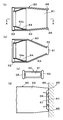
図1は本考案の一実施形態の洗浄吸引装置の全体構成を概略的に示す説明図、図2は前記装置の噴霧手段の部分を拡大し、その構成を概略的に示す縦断面図、図3は前記装置の汚物及び水分捕集管部の部分を拡大し、その構成を概略的に示す縦断面図、図4は前記捕集管部の部分を分解し、その構成を概略的に示す説明図、図5は前記捕集管部内に収容したカートリッジフィルター部の構成を概略的に示す説明図、図6は前記装置の吸引ノズル部の構成を概略的に示す説明図、図7は前記捕集管部の作用説明図である。 FIG. 1 is an explanatory diagram schematically showing the overall configuration of a cleaning and suction apparatus according to an embodiment of the present invention, and FIG. 2 is a longitudinal sectional view schematically showing the configuration of an enlarged portion of the spray means of the apparatus. 3 is a longitudinal cross-sectional view schematically showing the configuration of the filth and moisture collecting tube portion of the apparatus, and FIG. 4 is an exploded view of the collecting tube portion and schematically showing the configuration. FIG. 5 is an explanatory diagram schematically showing the configuration of the cartridge filter unit housed in the collection tube unit, FIG. 6 is an explanatory diagram schematically showing the configuration of the suction nozzle unit of the device, and FIG. It is operation | movement explanatory drawing of a collection pipe part.
上記図1〜図7において、この実施形態の洗浄吸引装置は、水等の洗浄液を空気と共に噴霧する洗浄液噴霧装置1と、汚物及び水分を吸引して捕集する汚物・水分吸引捕集装置2とを備えている。
1 to 7, the cleaning and suction device of this embodiment includes a cleaning liquid spraying device 1 that sprays a cleaning liquid such as water together with air, and a filth / water
前記噴霧装置1は、オゾン発生器10と、この発生器10へ圧力空気を送給する空気送給手段11と、水(水道水等)やぬるま湯等の洗浄液W(図2参照)を収容する容器12と、前記洗浄液Wを空気と一緒に噴霧する噴霧手段30とを備えている。
The spray device 1 contains an
前記オゾン発生器10は下端にキャスター13を取付けた箱型のユニットケース14内に設けてある。この実施形態のオゾン発生器10は空気導入口15及び空気排出口16を有する外筒17と、この外筒17内に配設されて紫外線(オゾン線)を照射する任意本数の紫外線ランプ18とを有している。前記ランプ18は交換可能に設けてある。前記ランプ18は、図示しない電源から漏電ブレーカ、安定器19(チョークボックス)を経て送られる電力により点灯させるように構成してある。
The
前記空気送給手段11はコンプレッサー、ブロアーポンプ或いは送風機等で構成され、接続ホース20を介して外筒17の空気導入口15と接続してケース14内に配設されている。前記空気送給手段11はモータ(図示せず)で稼動する。これにより、空気送給手段11から外筒17内へ送られる圧力空気は紫外線ランプ18から照射される紫外線が作用してオゾン含有の空気となり、このオゾン含有の空気は排出口16から圧力送出される。
The air feeding means 11 is composed of a compressor, a blower pump, a blower or the like, and is connected to the
前記噴霧手段30は洗浄液Wを前記空気(この実施形態ではオゾン含有空気)と一緒に噴霧させるものである。この実施形態の噴霧手段30は塗装用等のスプレーガン型に構成したものが採用され、噴霧器本体31を備える。噴霧器本体31は、図2に詳細に示すように、握持部32と、この握持部32と一体形成した胴体部33と、先端中心部に噴射口34を有し、胴体部33の先端に取付けたノズル部35とを備える。また、前記本体31は先端中心部に噴射口34と対向するノズル口36(弁座口)を有し、胴体部33内の先端側に設けた液体誘導室37と、前記室37内を気密性を保持して前進・後退自在に設けられ、先端38aでノズル口36を開閉するニードル弁棒38とを備える。また、軸39を支点として回動自在、かつ、前記弁棒38と係合40させると共に復帰バネ41で復帰する操作レバー42を有し、レバー42を操作(握持部32側に引く)することにより前記ノズル口36を開口させるように構成してある。
さらにまた、前記噴射口34と連通して形成した空気流通路43と、この流通路43と握持部32の下端に設けたジョイント管44とを接続して設けた空気輸送管45とを有している。
The spraying means 30 sprays the cleaning liquid W together with the air (in this embodiment, ozone-containing air). As the spray means 30 of this embodiment, a spray gun type for painting or the like is adopted, and a
Furthermore, an
前記ジョイント管44の基端突出部44aは、両端に取付用のソケット21,22を設けた適当な長さの空気輸送管23を介してオゾン発生器10の空気排出口16と接続されている。これにより、オゾン発生器10から圧力送出されるオゾン含有空気は輸送管23及び45、空気流通路43を通って噴射口34から外部に噴射させるように構成してある。
The base
前記容器12は適当な大きさ(容積)に形成され、内部に水道水等の洗浄液が収容されている。この実施形態の容器12は外周面にネジ溝を刻設したネジ口部24を有し、このネジ口部24を前記液体誘導室37の適当部(図示では上部側)に、前記室37と連通させて設けたネジ筒部46に螺合させて胴体部33の先端部側へ着脱自在に取付けてある。容器12の底部(図示では上部側)には着脱自在に設けた蓋部材25を有し、蓋部材25には空気孔26が形成されている。これにより、容器12内に収容されている洗浄液Wはネジ口部24から液体誘導室37内へ順次導入するように構成してある。
The
上記構成により、噴射口34から前記空気が噴射すると、噴射口34の内部側に空気の噴射圧力により負圧が発生する。そこで、ノズル口36を開口すると、前記室37内の液Wは前記空気圧(負圧)により吸引され、霧状化されて前記空気と共に噴霧される。この場合、本実施形態において、オゾン含有空気を使用しているため、前記液Wには前記空気が混入してオゾン含有液体(オゾン溶液)となり、このオゾン含有液体が前記空気と共に噴射口34から噴霧される。
With the above configuration, when the air is injected from the
図2において、47は胴体部33の適当部に摺動自在に設けた係合爪で、この爪47は前記レバー42の回動範囲を規制するために設けたものである。また、48は前記弁棒38の後端部に位置させて胴体部33の後端に設けたキャップ体、49は前記誘導室37に設け、前記弁棒38を気密性を保持して摺動(前進・後退)させるためのシール部材を示す。
In FIG. 2,
前記汚物・水分捕集装置2は、汚物及び水分捕集管部50と、この捕集管部50の一端側に設けられる吸引ノズル部60と、前記捕集管部50の他端側に後述するホースを介して接続して設けたバキューム手段70と、前記捕集管部50内に出し入れ自在に収容されるカートリッジフィルター部80とを備えている。
The filth /
前記捕集管部50は、適当な径(例えば手で握れるサイズ)及び適当な長さの円管状に形成されている。捕集管部50の前記他端(後端)には空気を流通する中心孔51を有し、後述するソケット部材を嵌合して連結するエンドキャップ52が気密性を保持させ、かつ、着脱自在に嵌合して取付けてある。前記キャップ52の内壁面は中心孔51に向けて径が細くなるテーパー部53が形成されている。
The
本実施形態の前記捕集管部50は、前記フィルター部80を収容するメイン収容室54と、前記捕集管部50内に固定して設けた空気流通性の仕切体55を介して捕集管部50内の後端部側に形成した補助用のフィルター収容室56を有している。補助用の吸水性フィルター57は吸水性のスポンジ材等で構成され、前記収容室56内に出し入れ自在に収容される。この場合、補助用の吸水性フィルター57は所望に応じて設けるもので省略してもよい。前記フィルター57を設けない構成を採用する場合には、補助用のフィルター収容室56も省略できる。この場合、仕切体55も省略できるが、仕切体55は捕集管部50の他端部近くに設け、カートリッジフィルター部80の捕集管部50の他端側方向への動きを規制する規制体の役目をなすように構成することもできる。
The
前記バキューム手段70は吸引ポンプ等で構成され、ケース14内に配置固定して設けてある。バキューム手段70はモータ(図示せず)で稼動させるように構成してある。バキューム手段70の吸込口71は両端に取付用のソケット部材72,73を設けた適当長さのホース74を介して捕集管部50の前記キャップ52と接続されている。これにより、バキューム手段70を稼動することにより、吸引ノズル部の先端(吸込口)から排泄汚物及び水分等を吸引するように構成してある。
The vacuum means 70 is constituted by a suction pump or the like, and is disposed and fixed in the
前記カートリッジフィルター部80は、吸水ノズル部60の吸込口から吸引される排泄汚物及び水分等を捕集するものである。前記フィルター部80は、一端を開口81すると共に他端部側に空気流通性の蓋部材82を有する筒状(円筒状)のハウジング83と、前記開口81した一端部側に所望の空間部84を形成してハウジング83内に充填した吸水性フィルター部材85とを備えて構成されている。
The
前記ハウジングの筒状体(円筒状)83aは捕集管部50のメイン収容室54と対応する直径及び前記仕切体55から捕集管部50の一端(開口81側端)までの長さ(寸法)より所望の長さ(例えば約5ミリ〜約15ミリ程度)だけ長く形成した筒状に構成されている。筒状体83aの構成素材は特に限定するものではないが、例えば厚紙材やプラスチック等を採用できる。前記蓋部材82としては、例えば任意素材のメッシュ材や網状部材等を採用することができる。但し、上記に限定されるものではない。
A cylindrical body (cylindrical shape) 83a of the housing has a diameter corresponding to the
前記フィルター部材85は上述した作用を有する任意の素材で形成したものを採用できる。本実施形態のフィルター部材85は、図5(a),(e)等に示すように、直径約2〜5ミリ、長さ約4〜約8ミリ程度のペレット状に形成した吸水性及び消臭性を有する紙材で構成したものを採用した例が開示されている。上述した紙材製のフィルター部材85としては、例えば猫のトイレ用の砂として一般に市販されている猫のトイレ用の砂(例えばツーズイツハラ株式会社製の商品名:ネコットのエコッペ)等を採用することができる。
The
前記フィルター部材85は上述したように、前記開口81した一端部側に適当な大きさ(広さ)の空間部84を形成してハウジング83内に充填されている。前記空間部84は後述するガイド体のガイド筒部を挿入するために設けたものである。また、この実施形態のフィルター部80は、前記フィルター部材85をハウジング83内に充填した後、その上からメッシュ材や網状部材等で形成した空気流通性の押え用蓋部材86を設けた例が開示されている。前記蓋部材86はフィルター部材85がハウジング83内から不用意にこぼれ落ちないようにするために設けたものである。
As described above, the
前記カートリッジフィルター部80は、前記一端部側(開口81部側)を捕集管部50の一端(開口81側端)から管部50外へ突出させて捕集管部50の収容室54内へ出し入れ自在に収容される。本実施形態では上述したように、ハウジングの筒状体83aの長さを収容室54の長さ(仕切体55から開口81側端までの長さ)より長く形成した部分(約5ミリ〜約15ミリ)が管部50外へ突出するように構成されている。フィルター部80を交換する際には、ハウジング83の前記突出端部を手の指等で摘む等により収容室54から簡単に引き出すことができる。
The
なお、前記フィルター部材85は一例として開示したもので、このフィルター部材85は図示のものに限定するものではなく、上述した作用を有する任意の構成のものを採用することができる。例えば、その一例として、炉紙材等の吸水性紙材や吸水性の不織布材、或いは吸水性のスポンジ材等で所定の大きさの円柱状に形成したものを挙げることができる。この場合において、円柱状に形成した吸水性フィルター部材を採用する場合には、フィルター部材の一端側の中央部に被吸引物導入用の凹所を形成し、この凹所側の端部をハウジング83の開口81側に向けてハウジング83内に収容するように構成するのが好ましい。このように構成すると、ハウジング内に吸引された排泄汚物は前記凹所内に導入されて捕集される。なお、上記のように形成した吸水性フィルター部材は前記と同様に、開口81した一端部側に適当な空間部84を形成してハウジング83内に収容するように構成する。
The
前記吸引ノズル部60は、一端に吸込口61を有すると共に他端側に捕集管部50の一端側(開口81端側)に着脱自在に嵌合する嵌合筒部62を有するノズル本体63と、この本体63内に固定して設けたガイド体64とを備えている。ガイド体64は両端を開口した筒状体(円筒状体)で形成され、前記嵌合筒部62側方向に次第に縮径するガイド筒部64aを有している。この実施形態では、ガイド体64とノズル本体63とを別体に形成し、両者64,63を接着等により固定した例が開示されているが、ガイド体64はノズル本体63と一体形成することもできる。
The
前記ノズル部60は、ガイド筒部64aを前記空間部84内に挿入すると共に気密性を保持して嵌合筒部62を捕集管部50の一端側に気密性を保持して着脱自在に嵌合して取付ける。なお、この場合、ノズル部60の嵌合筒部62と捕集管部50の一端部にロック手段を設け、例えば嵌合筒部62を捕集管部50に嵌合した状態でノズル部を所定角度回動することによりノズル部60を捕集管部50にロック固定して脱抜を防止し、ノズル部を元の位置に回動することにより前記ロックを解除する構成を採用することもできる。
The
また、本実施形態のノズル部60は、吸込口61の両端部に隆起部65,65が相対向して設けてある。この隆起部65は図6(d),図7に示すように、ノズル部60の先端(吸込口61側端)を被介護者等の皮膚等66に当接した際に皮膚等と吸込口61との間に間隙部67を形成し、皮膚等に付着している排泄汚物68等や水分等の吸い込みを良好にするために設けたものである。この場合、前記隆起部65に代え、吸込口61の端面の全体を円弧状に形成し、ノズル部を皮膚等66に当接した際に皮膚等と吸込口との間に間隙部を形成する構成、或いは吸込口61の端面に任意数の切欠溝を形成する構成等を採用することもできる。
Further, the
本実施形態の洗浄吸引装置は、図1に示すように、オゾン発生器10の電源スイッチをON,OFF(開閉)操作するスイッチ操作部90と、空気送給手段11のモータのスイッチをON,OFF(開閉)操作するスイッチ操作部91と、バキューム手段70のモータのスイッチをON,OFF(開閉)操作するスイッチ操作部92を、ケース14の基板93上に配置して設けてある。
As shown in FIG. 1, the cleaning and suction apparatus of the present embodiment is configured such that a
本実施形態の洗浄吸引装置は上記のように構成したもので、次に使用方法の一例及び作用等につき説明する。オゾン発生器10のスイッチ操作部90を操作して電源スイッチをONにすると共に空気送給手段11のスイッチ操作部91を操作して空気送給手段11を稼動する。
The cleaning and suction apparatus of the present embodiment is configured as described above. Next, an example of the method of use and the operation will be described. The
空気送給手段11が稼動すると、圧力空気がオゾン発生器10の導入口15から外筒17内へ送給され、オゾン含有空気となって排出口16から圧力送出される。このオゾン含有空気は輸送管23を通って噴霧器本体31の輸送管45へ送給され、同管45,空気流通路43を通り、噴射口34から噴射される。この状態で本体30を手で握り、レバー42を操作(握持部32側に引く)して弁棒38を後退すると、ノズル口36が開くので、誘導室37内の洗浄液Wは前記空気の噴射圧力(負圧)により吸引されると共に順次霧状化されて、前記空気と共に噴霧される。そこで、噴霧口34を例えば寝たきり高齢者等の排泄汚物68等が付着している部位に向けることにより、皮膚等66に付着して残っている汚物68等はきれいに洗浄されて除去される。また、レバー42を開放すると、レバー42はバネ41の作用で復帰するので、弁棒38は前進し、ノズル口36は閉じて液Wの噴霧は停止する。そして、上記洗浄作業を終了後、スイッチ操作部90,91を操作してオゾン発生器の電源スイッチ及び空気送給手段のモータのスイッチをOFFにする。
When the air feeding means 11 is operated, the pressure air is fed from the
次いで、バキューム手段71のスイッチ操作部92を操作してバキューム手段を稼動する。そして、図7に示すように、捕集管部50を手で握り、吸込口61を皮膚等66の所定部に当接するように向けると、前記洗浄により洗い落とされた汚物68等及び水分は吸込口からノズル本体63に吸引され、ガイド体64により案内されてカートリッジフィルター部80の空間部84の中央部側からフィルター部材85に導入される。そして、フィルター部材を通過する間に汚物等及び水分は、上述したようにフィルター部材85で全て捕集され、空気だけが補助用のフィルター57及びホース74を通って排出される。
Subsequently, the vacuum means is operated by operating the
上記したように、吸込口から吸引された汚物等及び水分はフィルター部材を通過する間に、フィルター部材によって、吸水・吸着されて全て捕集されるので、ホースの内壁面及び空気送給手段に排泄汚物等が付着して汚染するのを防止できる。 As described above, while the dirt and moisture sucked from the suction port pass through the filter member, they are absorbed and adsorbed by the filter member so that they are all collected, so that they are collected on the inner wall surface of the hose and the air feeding means. It is possible to prevent excreta and the like from adhering and contaminating.
また、吸込口から吸引された汚物等及び水分は、上述したように、ガイド体64のガイド筒部64aにより案内されてフィルター部材に導入されて捕集されるので、ハウジング83の前記開口81した突出端部に排泄汚物等や水分が付着して汚染するのを防止できる。
Further, as described above, the dirt and the like sucked from the suction port are guided by the
前記カートリッジフィルター部80は、所望時、通常は1回の洗浄作業毎に新しいものと交換する。フィルター部80を交換する際には、ハウジング83の前記突出端部を手の指等で摘んで引っ張ることにより、収容室54から容易に引き出せるので、フィルター部の取替え作業が簡単になる。また、ハウジングの前記突出端部は上述したように排泄汚物等や水分が付着していないので、フィルター部の交換作業を行う際に、作業者が汚物等により手等を汚染するのを確実に防止できる。
The
なお、補助用の前記フィルター57は、上述したように、空気だけが通過するので汚物等や水分により汚染されない。そのため、このフィルター57は1回の洗浄作業毎に交換する必要はなく、所望に応じて適当な時期に交換すればよいものである。
As described above, the
また、本実施形態ではオゾン発生器10を備え、オゾン含有空気を洗浄液と一緒に噴霧させるように構成したので、上述した作用効果に加え、次のような作用効果を奏する。(1)排泄汚物等の臭気を最低レベルに脱臭できる。(2)汚物等が付着している皮膚等の殺菌及び消毒をすることができる。(3)汚物洗浄後の皮膚等を活性化する効果が期待できる。
上記したように、オゾン発生器を設けることにより上述したような作用効果を奏するが、オゾン発生器は所望に応じて採用するものであり、省略することも可能である。
In the present embodiment, since the
As described above, by providing an ozone generator, the above-described effects can be obtained. However, the ozone generator is employed as desired and can be omitted.
なお、本実施形態の洗浄液噴霧装置1の噴霧手段30は一例として開示したもので、この噴霧手段30は上記構成のものに限定されるものではない。例えば、特開2004−275701号公報(特許文献2)の実施形態1等に記載(同公報0016〜0037、図1、図2等参照)されているように、空気噴射管と、液体吸い上げ管と、空気送給手段とを備え、噴射管の噴射口から噴射される空気の空気圧を利用して容器内の洗浄液を吸い上げ管を通じて吸い上げて空気と一緒に噴霧させるように構成した方式のもの、その他の任意の構成に変更可能なものである。要は容器内に収容されている洗浄液を噴射口から空気(圧力空気)と一緒に噴霧させるように構成すればよいものである。 In addition, the spraying means 30 of the cleaning liquid spraying apparatus 1 of this embodiment is disclosed as an example, and the spraying means 30 is not limited to the above-described configuration. For example, as described in Embodiment 1 of JP-A-2004-275701 (Patent Document 2) (see the publications 0016 to 0037, FIG. 1, FIG. 2, etc.), an air injection pipe and a liquid suction pipe And an air feeding means, and using a pneumatic pressure of the air jetted from the jet port of the jet pipe, the cleaning liquid in the container is sucked up through the suction pipe and sprayed together with the air, It can be changed to any other configuration. The point is that the cleaning liquid contained in the container may be sprayed together with air (pressure air) from the injection port.
1 洗浄液噴霧装置
2 汚物・水分吸引捕集装置
50 汚物及び水分捕集管部
60 吸引ノズル
61 吸込口
62 嵌合筒部
64 ガイド体
64a ガイド筒部
70 バキューム手段
74 ホース
80 カートリッジフィルター部
81 開口
82 蓋部材
84 空間部
85 吸水性フィルター部材
DESCRIPTION OF SYMBOLS 1 Cleaning
Claims (3)
前記噴霧装置は、圧力空気を送給する空気送給手段と、洗浄液を収容する容器と、前記空気送給手段の稼動時に前記洗浄液を前記空気と一緒に噴霧させる噴霧手段とを備え、
前記捕集装置は、汚物及び水分捕集管部と、この捕集管部の一端側に設けられる吸引ノズル部と、前記捕集管部の他端側にホースを介して接続して設けたバキューム手段と、前記捕集管部内に出し入れ自在に収容されるカートリッジフィルター部とを備え、
前記フィルター部は、一端を開口すると共に他端部に空気流通性の蓋部材を有する筒状のハウジングと、前記開口した一端部側に所望の空間部を形成して前記ハウジング内に充填した吸水性フィルター部材とを備え、前記一端部側を前記捕集管部の前記一端側から前記管部外へ突出させて前記捕集管部内へ収容するように構成され、
前記ノズル部は、一端に吸込口を有すると共に他端部に前記捕集管部に着脱自在に嵌合する嵌合筒部を有するノズル本体と、この本体内に固定して設けられ、両端を開口した筒状体で形成されていると共に前記筒部側方向に次第に縮径するテーパーを付したガイド筒部を有するガイド体とを備え、
前記ノズル部は、前記ガイド筒部を前記空間部内に挿入して、前記捕集管に取付けるように構成されている
ことを特徴とする、洗浄吸引装置。 A cleaning suction device, comprising a cleaning liquid spraying device and a filth / water suction collecting device,
The spraying device includes an air feeding unit that feeds pressurized air, a container that stores a cleaning liquid, and a spraying unit that sprays the cleaning liquid together with the air when the air feeding unit is in operation.
The collection device was provided by connecting a filth and moisture collection tube portion, a suction nozzle portion provided on one end side of the collection tube portion, and the other end side of the collection tube portion via a hose. A vacuum means, and a cartridge filter part that is detachably accommodated in the collecting pipe part,
The filter part has a cylindrical housing having an opening at one end and an air-flowable lid member at the other end, and a water absorption unit that fills the housing by forming a desired space on the opened one end side. A filter member, and is configured to project the one end side from the one end side of the collection pipe part to the outside of the pipe part and accommodate it in the collection pipe part,
The nozzle part is provided with a nozzle body having a suction port at one end and a fitting cylinder part that is detachably fitted to the collecting pipe part at the other end, and is fixedly provided in the body. A guide body that is formed of an open cylindrical body and has a guide cylinder portion with a taper that gradually decreases in diameter in the direction of the cylinder portion;
The cleaning and suction device, wherein the nozzle portion is configured to be inserted into the space portion and attached to the collecting tube.
Priority Applications (1)
| Application Number | Priority Date | Filing Date | Title |
|---|---|---|---|
| JP2008000960U JP3141501U (en) | 2008-02-22 | 2008-02-22 | Cleaning suction device |
Applications Claiming Priority (1)
| Application Number | Priority Date | Filing Date | Title |
|---|---|---|---|
| JP2008000960U JP3141501U (en) | 2008-02-22 | 2008-02-22 | Cleaning suction device |
Publications (1)
| Publication Number | Publication Date |
|---|---|
| JP3141501U true JP3141501U (en) | 2008-05-08 |
Family
ID=43291556
Family Applications (1)
| Application Number | Title | Priority Date | Filing Date |
|---|---|---|---|
| JP2008000960U Expired - Fee Related JP3141501U (en) | 2008-02-22 | 2008-02-22 | Cleaning suction device |
Country Status (1)
| Country | Link |
|---|---|
| JP (1) | JP3141501U (en) |
Cited By (2)
| Publication number | Priority date | Publication date | Assignee | Title |
|---|---|---|---|---|
| JP2010022792A (en) * | 2008-07-22 | 2010-02-04 | Kiyomi Unozawa | Apparatus for automatically discharging bubbles containing ozone gas |
| CN109419407A (en) * | 2017-08-23 | 2019-03-05 | 惠州进盈塑胶五金制品有限公司 | A kind of novel Oil injection pot |
-
2008
- 2008-02-22 JP JP2008000960U patent/JP3141501U/en not_active Expired - Fee Related
Cited By (3)
| Publication number | Priority date | Publication date | Assignee | Title |
|---|---|---|---|---|
| JP2010022792A (en) * | 2008-07-22 | 2010-02-04 | Kiyomi Unozawa | Apparatus for automatically discharging bubbles containing ozone gas |
| CN109419407A (en) * | 2017-08-23 | 2019-03-05 | 惠州进盈塑胶五金制品有限公司 | A kind of novel Oil injection pot |
| CN109419407B (en) * | 2017-08-23 | 2024-03-26 | 惠州进盈塑胶五金制品有限公司 | Novel oil spraying kettle |
Similar Documents
| Publication | Publication Date | Title |
|---|---|---|
| US7703170B2 (en) | Self-cleaning wet dry vacuum cleaning device | |
| US20050015916A1 (en) | Wet-dry vacuum cleaning device | |
| KR101254769B1 (en) | Toilet seat cleaning device and consumable cartridge for the same | |
| US8925142B2 (en) | Apparatus for cleaning waste from a surface | |
| KR101586301B1 (en) | Toothbrush sterilization device having Ultrasonic cleaning means | |
| JP3141501U (en) | Cleaning suction device | |
| CN215874510U (en) | Base station | |
| JP4135175B2 (en) | Cleaning suction device | |
| JPH11137506A (en) | Endoscope cleaning and disinfecting equipment | |
| JP2020062533A (en) | Cleaning and processing equipment for medical and nursing care containers | |
| KR20190060455A (en) | Oral cleaner | |
| KR100432064B1 (en) | Vacuum cleaner for prevention of the breeding and extermination | |
| KR20180047315A (en) | Flush toilet having a separate urinal fow male | |
| KR20210151358A (en) | Disinfectant Spray | |
| JP2002165821A (en) | Excreta disposer | |
| KR20210006187A (en) | Water spray typed mop | |
| JP2000051313A (en) | Excrement disposal implement | |
| JP7104614B2 (en) | Electric cleaning device | |
| KR200358834Y1 (en) | deodorizer and sterilizer for a vehicle for collecting waste | |
| KR200359796Y1 (en) | Having nozzle cover unit bidet | |
| JP3221577U (en) | Waste collection machine | |
| JP2001218783A (en) | Washing device for nursing and excreta processor for nursing | |
| CN221285973U (en) | Oral cavity cleaner | |
| JP3725679B2 (en) | Endoscope cleaning and disinfection device | |
| CN218870204U (en) | Dull and stereotyped mop with spraying function of disinfecting |
Legal Events
| Date | Code | Title | Description |
|---|---|---|---|
| R150 | Certificate of patent or registration of utility model |
Free format text: JAPANESE INTERMEDIATE CODE: R150 |
|
| FPAY | Renewal fee payment (event date is renewal date of database) |
Free format text: PAYMENT UNTIL: 20110416 Year of fee payment: 3 |
|
| FPAY | Renewal fee payment (event date is renewal date of database) |
Free format text: PAYMENT UNTIL: 20110416 Year of fee payment: 3 |
|
| FPAY | Renewal fee payment (event date is renewal date of database) |
Free format text: PAYMENT UNTIL: 20120416 Year of fee payment: 4 |
|
| FPAY | Renewal fee payment (event date is renewal date of database) |
Free format text: PAYMENT UNTIL: 20120416 Year of fee payment: 4 |
|
| FPAY | Renewal fee payment (event date is renewal date of database) |
Free format text: PAYMENT UNTIL: 20130416 Year of fee payment: 5 |
|
| FPAY | Renewal fee payment (event date is renewal date of database) |
Free format text: PAYMENT UNTIL: 20130416 Year of fee payment: 5 |
|
| FPAY | Renewal fee payment (event date is renewal date of database) |
Free format text: PAYMENT UNTIL: 20140416 Year of fee payment: 6 |
|
| LAPS | Cancellation because of no payment of annual fees |