JP3142402U - Water control valve - Google Patents
Water control valve Download PDFInfo
- Publication number
- JP3142402U JP3142402U JP2008001943U JP2008001943U JP3142402U JP 3142402 U JP3142402 U JP 3142402U JP 2008001943 U JP2008001943 U JP 2008001943U JP 2008001943 U JP2008001943 U JP 2008001943U JP 3142402 U JP3142402 U JP 3142402U
- Authority
- JP
- Japan
- Prior art keywords
- housing
- packing material
- side wall
- lid
- peripheral surface
- Prior art date
- Legal status (The legal status is an assumption and is not a legal conclusion. Google has not performed a legal analysis and makes no representation as to the accuracy of the status listed.)
- Expired - Fee Related
Links
Images




Landscapes
- Valve Housings (AREA)
Abstract
【課題】上部筐体と蓋体との間に土砂の浸入を防止できる制水弁筺を提供する。
【解決手段】上面周縁に環状凸部を突設してなる下部筺体11と、前記下部筺体の環状凸部11bを嵌入して載置固定する中間筺体12と、前記中間筺体に嵌着する上部筺体13と、前記上部筺体に嵌着される蓋体14とからなり、前記上部筐体の上部内周面と蓋体の側壁外周面との間にパッキン材17を配設したことを特徴とする。前記パッキン材は、上部筐体の内周面に取り付けられており、蓋体を上部筐体に嵌着したとき、蓋体の側壁外周面に圧接するように配設することができる。また、蓋体の側壁は下方に窄まっており、前記側壁の下端先端面の径はパッキン材の内径よりも小さく形成されていて、パッキン材は、蓋体を上部筐体に嵌着したときに蓋体の側壁外周面に圧接するように配設してもよい。
【選択図】図1To provide a water control valve rod capable of preventing infiltration of earth and sand between an upper housing and a lid.
A lower housing 11 having an annular convex portion projecting from the periphery of the upper surface, an intermediate housing 12 in which the annular convex portion 11b of the lower housing is fitted and fixed, and an upper portion fitted to the intermediate housing. It comprises a housing 13 and a lid body 14 fitted to the upper housing, and is characterized in that a packing material 17 is disposed between an upper inner peripheral surface of the upper housing and a side wall outer peripheral surface of the lid body. To do. The packing material is attached to the inner peripheral surface of the upper casing, and can be disposed so as to come into pressure contact with the outer peripheral surface of the side wall of the lid when the lid is fitted to the upper casing. Further, the side wall of the lid body is narrowed downward, and the diameter of the lower end tip surface of the side wall is formed smaller than the inner diameter of the packing material, and the packing material is used when the lid body is fitted to the upper housing. You may arrange | position so that it may press-contact with the side wall outer peripheral surface of a cover body.
[Selection] Figure 1
Description
本考案は、地中に埋設した水道管に接続されている制水弁を内部に配設する
制水弁筺に関する。
The present invention relates to a water control valve rod in which a water control valve connected to a water pipe buried in the ground is disposed.
従来、制水弁筺を地中に配設する場合に、水道管に接続されている制水弁が凍結しないように、地表面から深く、例えば、1m以上の深さに埋設される。例えば、従来は、地中に埋設された水道管に制水弁が接続されている。 Conventionally, when a water control valve rod is disposed in the ground, it is buried deep from the ground surface, for example, at a depth of 1 m or more so that the water control valve connected to the water pipe does not freeze. For example, conventionally, a water control valve is connected to a water pipe buried in the ground.
さらに、水道管の上に制水弁を囲むように一定の間隔を明けて砂を水で固めた基礎を形成し、前記基礎の上に制水弁筺を載置固定し、周囲を埋め戻して埋設していた。 In addition, a foundation is formed on the water pipe that surrounds the water control valve with a certain interval, and sand is hardened with water. Was buried.
前記制水弁筺は、下端部が湾曲して拡径した円筒状の下部筺体と、蓋体を着脱自在に嵌着する上部筺体とから構成されている。下部筺体の上部には雄ねじが設けられており、一方、上部筺体には前記雄ねじと螺合する雌ねじが設けられている。前記雄ねじと雌ねじとを螺合させることによって一体に組み立てるとともに、螺合の長さによって蓋体の地表面との高さ位置を調節するものである。 The water control valve rod is composed of a cylindrical lower housing whose lower end is curved and expanded in diameter, and an upper housing on which a lid is detachably fitted. A male screw is provided on the upper part of the lower housing, while a female screw that is screwed with the male screw is provided on the upper housing. The male screw and the female screw are assembled together by being screwed together, and the height position of the lid body with respect to the ground surface is adjusted by the length of the screwing.
上記構成の制水弁筺は、一般に鋳造品である。そのために、長期間の埋設によって錆が生じたり、前記雄ねじと雌ねじの間に土砂等が入って雄ねじと雌ねじとは回転できないことがある。そこで、実際に、沈下などによって制水弁筺全体の高さが低くなった場合や、地表面の補修や再舗装工事等によって蓋体の高さ位置を調節する必要がある場合に、下部筺体に対して上部筺体を回転させることができず、高さ調節ができないという問題がある。 The water control valve having the above-described configuration is generally a cast product. Therefore, rusting may occur due to long-term embedding, or earth and sand may enter between the male screw and the female screw, and the male screw and the female screw may not rotate. Therefore, when the overall height of the water control valve rod is actually lowered due to subsidence, etc., or when it is necessary to adjust the height position of the lid body by repairing the ground surface or re-paving, etc. However, there is a problem that the upper casing cannot be rotated and the height cannot be adjusted.
この考案は、かかる現況に鑑みてなされたもので、内部に土砂等が入らず高さ調節の際の分解が容易である制水弁筺を提供することを目的としている。また、この考案は、構造が簡単で安価にでき、組立も容易な制水弁筺を提供することを目的としている。 The present invention has been made in view of the present situation, and an object thereof is to provide a water control valve that can be easily disassembled when the height is adjusted without containing earth and sand. Another object of the present invention is to provide a water control valve that has a simple structure and can be inexpensively assembled.
この考案は、上記目的を達成するために次のような構成とした。即ち、この発明の制水弁筺は、上面周縁に環状凸部を突設してなる下部筺体と、前記下部筺体の環状凸部を嵌入して載置固定する中間筺体と、前記中間筺体に嵌着する上部筺体と、前記上部筺体に嵌着される蓋体とからなり、前記上部筐体の上部内周面と蓋体の側壁外周面との間にパッキン材を配設したことを特徴とする。前記パッキン材は、上部筐体の内周面に取り付けられており、蓋体を上部筐体に嵌着したとき、蓋体の側壁外周面に圧接するように配設することができる。また、蓋体の側壁は下方に窄まっており、前記側壁の下端先端面の径はパッキン材の内径よりも小さく形成されていて、パッキン材は、蓋体を上部筐体に嵌着したときに蓋体の側壁外周面に圧接するように配設されていることが好ましい。 In order to achieve the above object, the present invention has the following configuration. That is, the water control valve rod of the present invention includes a lower housing formed by projecting an annular convex portion on the upper surface periphery, an intermediate housing that fits and fixes the annular convex portion of the lower housing, and the intermediate housing. An upper casing to be fitted and a lid fitted to the upper casing, and a packing material is disposed between the upper inner peripheral surface of the upper casing and the side wall outer peripheral surface of the lid. And The packing material is attached to the inner peripheral surface of the upper casing, and can be disposed so as to come into pressure contact with the outer peripheral surface of the side wall of the lid when the lid is fitted to the upper casing. Further, the side wall of the lid body is narrowed downward, and the diameter of the lower end tip surface of the side wall is formed smaller than the inner diameter of the packing material, and the packing material is fitted when the lid body is fitted to the upper housing. It is preferable to arrange | position so that it may press-contact to the side wall outer peripheral surface of a cover body.
前記パッキン材は、断面コの字状の環状体であってもよいし、断面円形状の環状体であってもよい。パッキン材の形状は任意に形成することができる。また、パッキン材は、蓋体の側壁外周面に取り付けられており、上部筐体の上部開口部の内径は、前記パッキン材の外周面における直径よりも大きく形成するようにしてもよい。 The packing material may be an annular body having a U-shaped cross section or an annular body having a circular cross section. The shape of the packing material can be arbitrarily formed. The packing material may be attached to the outer peripheral surface of the side wall of the lid, and the inner diameter of the upper opening of the upper housing may be formed larger than the diameter of the outer peripheral surface of the packing material.
この考案にかかる制水弁筺によれば、組立設置が容易であるばかりでなく、上部筐体と蓋体の間にパッキン材を配設したから、土砂や雨水の浸入を防止することができる。また、中間筐体にプラスチック製中間筐体を使用することによって、錆によって取り外しができなくなるということはない。また、中間筐体と下部筐体との嵌合は、下部筐体の環状凸部を中間筐体に嵌入し、中間筐体を下部筐体の外側に位置するようにしたから、構造が簡単であるとともに、土砂や雨水の浸入を防止することができるばかりでなく、蓋体を容易に取り外すことができる。 According to the water control valve rod according to the present invention, not only the assembly and installation are easy, but also the packing material is disposed between the upper housing and the lid body, so that intrusion of earth and sand and rainwater can be prevented. . Further, by using a plastic intermediate casing for the intermediate casing, it is not possible to remove the intermediate casing due to rust. In addition, the intermediate housing and the lower housing can be fitted with a simple structure because the annular protrusion of the lower housing is fitted into the intermediate housing and the intermediate housing is positioned outside the lower housing. In addition, it is possible not only to prevent intrusion of earth and sand and rainwater, but also to easily remove the lid.
以下に、この考案を図示する実施形態に基づいて詳細に説明する。図1〜図3は、この考案の第1実施形態を示す。制水弁筺10は、基礎の上に載置固定される下部筺体11、中間筺体12、上部筺体13、及び蓋体14によって構成されている。
Hereinafter, the present invention will be described in detail based on the illustrated embodiment. 1 to 3 show a first embodiment of the present invention. The water
前記下部筺体11は、側面が下部に向かって末広がりに湾曲した略椀状に形成されている。上面はほぼ水平面11aに形成されており、前記水平面11aに前記中間筺体12に嵌入する環状凸部11bが一体に突設されている。従って、前記環状凸部11bの外径は、前記中間筐体12の内径と同じか僅かに小さく形成されている。中間筐体12を環状凸部11bの外側に配設することによって、パッキン材を用いることなく土砂の浸入を防止することができる。
The
尚、前記下部筺体11は、前記形状に限定されるものではなく、側面を垂直に形成した円筒体であってもよく、また、側面を傾斜させ、あるいは段状に形成した中空の円錐台の形状であってもよい。
The
前記中間筺体12は、適宜の長さのプラスチック製円筒体であって、蓋体14の地表面との高さ位置を調節する高さ調整部材である。中間筐体12は、予め上部筺体13及び蓋体14の上面が地表面と同一になる高さを測定しておいて、その高さとなる長さのものを使用する。この中間筐体12によって制水弁筺10全体の高さが調節される。中間筐体12の長さの決定方法については後述する。
The
次に、前記上部筺体13は、全体が円筒状体であって、内周面に蓋体14を載置する内向きのフランジ13aが設けられており、前記フランジ13aの内周面の適宜の位置に透孔を有する突片13bが突設されている。前記突片13bに、蓋体14の下面に取り付けた鎖、ひも等を固着し(図示するのは省略する)、蓋体14が持ち去られるのを防止する。
Next, the
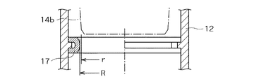
また、上部筐体13のフランジ13aより上方の内周面に蓋体14との密閉性を高めるパッキン材17が取り付けられている。前記パッキン材17は、図2及び図3に示すように、断面コの字状に形成された円環状体であって、外周面側の凹部17aに上部筐体13の内周面に突設した突起13cを嵌合させることによって取り付けられている。
A
パッキン材17は、ゴムまたはプラスチック製弾性体であって、内周面が前記蓋体14の側壁14bに圧接している。パッキン材17が蓋体14の側壁14bに圧接することによって、上部筐体13と蓋体14との隙間から土砂や水が侵入するのが防止され、中間筐体12、下部筐体11内をきれいに維持することができる。
The
蓋体14は、上板14aと側壁14bとによって形成されている。前記上板14aの上面は、中央部から外周縁に向かって僅かに傾斜しており、側壁14bの外周面は、パッキン材17を外方に押圧しながら嵌着するように下方が窄まっている。
The
さらに、蓋体14の上板14aの略中央部には、手かぎ穴などの平面円形状をした凹部14cが設けられている。前記凹部14cの上部には、取り出し棒などを係止する係止バーが水平に掛け渡されており、周面は上方外側に向かって傾斜している。このように、凹部14cの周面を傾斜させることによって、土砂等が堆積した場合でも容易に取り出すことができる。
Furthermore, a
上述のように、側壁14bが下方に窄まっていることによって、図2に示すように、側壁14bの下端面先端が、蓋体14を嵌着する前のパッキン材17の内周面に接する垂直線S(一転鎖線で示す)よりも垂直方向において内側に位置している。即ち、図2及び図3に示すように、側壁14bの下部外周面にテーパー面が設けられているとともに、パッキン材17の内径をRとし、側壁14bの下端面先端の内径をrとすると、R≧rとなるように形成されている。
As described above, when the
しかも、側壁14bの外周面は下方につぼまっているから、蓋体14を上部筐体13に嵌着したときに、パッキン材17は側壁14bの外周面によって徐々に押し広げられて、側壁14bの外周面に圧接することになる。
In addition, since the outer peripheral surface of the
前記パッキン材17は、蓋体14を取り付ける際には、蓋体14の側壁14bによって押し広げられるとともに、押し下げられることになるが、上部筐体13の内周面に設けた突起13cに係止されているから、ずり落ちることがなく、側壁14bに確実に圧接することになる。一方、蓋体14を上部筺体13から取り外す際には、側壁14bがつぼまっているとともに、パッキン材17は突起13cに係止されているから、容易に取り出すことができる。
When the
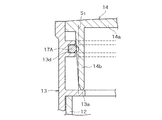
次に、上部筐体13と蓋体14との密閉性を高める第2の実施形態について説明する。上記第1実施形態では、パッキン材17を断面コの字状環状体に形成したのに対して、第2実施形態ではパッキン材17AをOリングのように断面円形状環状体に形成した。
Next, a second embodiment for improving the sealing performance between the
即ち、図4に示すように、上部筐体13のフランジ13aよりも上方の内面に環状凹部13d設け、前記環状凹部13dにパッキン材17Aの一部を嵌合してなる。この実施形態においても、蓋体14を容易に嵌着できるように、側壁14bの下端面先端が、蓋体14を嵌着する前のパッキン材17Aの内周面に接する垂直線S1(一転鎖線で示す)よりも垂直方向において内側に位置している。
That is, as shown in FIG. 4, an
側壁14bの外周面は下方につぼまっており、蓋体14を上部筐体13に嵌着したときに、パッキン材17Aは側壁14bの外周面によって徐々に押し広げられて、側壁14bの外周面に圧接するように構成されている。
The outer peripheral surface of the
なお、パッキン材17Aの断面形状は、図示する実施形態のように、断面円形状に限定されるものではなく、例えば、楕円、多角形等任意の形状とすることができる。他の構成について第1実施形態と同じであるから、同一構成については同一符号を付してその説明は省略する。
Note that the cross-sectional shape of the packing
図5は、さらに第3の実施形態を示す説明用断面図である。第2実施形態とは、パッキン17Bの取り付け位置が異なる。即ち、蓋体14の側壁14bの外面に環状凹部14c設け、前記環状凹部14cにパッキン材17Bの一部を嵌合してなる。
FIG. 5 is a cross-sectional view illustrating the third embodiment. The attachment position of packing 17B differs from 2nd Embodiment. That is, an
この実施形態においては、蓋体14を容易に嵌着できるように、上部筐体13の上部内面に上方に広がるテーパー面13eを設けてなり、前記テーパー面13eの上端は、蓋体14を嵌着する前のパッキン材17Bの外周面に接する垂直線S2(一転鎖線で示す)よりも垂直方向において外側に位置している。即ち、図5に示すように、パッキン材17Bの外径をR1とし、テーパー面13eの上端の内径をr1とすると、R1≦r1となるように形成されている。
In this embodiment, a
蓋体14を上部筐体13に嵌着したときに、パッキン材17Bは上部筐体13の上部内面に形成したテーパー面13eによって徐々に内側に押圧されながら上部筐体13の内周面に圧接する。
When the
なお、パッキン材17Bの断面形状は、パッキン材17Aと同じく断面円形状に限定されるものではなく、例えば、楕円、多角形等任意の形状とすることができる。他の構成については第1実施形態と同じであるから、同一構成について同一符号を付してその説明は省略する。
The cross-sectional shape of the packing
次に、図6に示すトンボ型定規について説明する。図示するトンボ型定規20は、物差20aとトンボ型スライダー20bとからなり、スライダー20bに物差20aを上下動可能なように挿入することによって構成されている。物差20aは、断面円形の棒状体であって、適宜の間隔で下端からの長さを表す目盛20cが設けられている。スライダー20bの高さ寸法Hは、図2に示す上部筐体13のフランジ13aの下面から上端までの寸法Hと同じく形成されている。
Next, the registration mark type ruler shown in FIG. 6 will be described. The registration
上部筐体13のフランジ13aの下面は、中間筐体12の上に載置されるから、スライダー20bの高さ寸法Hと、図2に示すように上部筐体13のフランジ13aの下面から上端までの寸法Hと同じく形成することによって、物差20aの下端を下部筺体11の水平面11aに載置するとともに、スライダー20bの上端面を道路面に合わせてスライダー20bの下端面の目盛を読むと、その目盛寸法が中間筐体12の長さとなる。
Since the lower surface of the
このように、スライダー20bの高さ寸法Hを上部筐体13のフランジ13aの下面から上端までの寸法Hと同一に形成すれば、物差20aの残りの目盛が中間筐体12の長さとなるから、中間筐体12の長さを容易に決定することができる。
Thus, if the height dimension H of the
次いで、第1実施形態の制水弁筐を図1のように組み立てて使用する場合について説明する。まず、基礎の上に下部筺体11を載置固定し、中間筺体12の下端部を前記下部筐体11の環状凸部11bに嵌合して取り付ける。実施形態において図示するのを省略したが、環状凸部11bと中間筐体12との嵌合部では、両者に締付けボルトを貫通させ雌ねじにより一体に組み立てるようにしてもよい。
Next, the case where the water control valve housing of the first embodiment is assembled and used as shown in FIG. 1 will be described. First, the
予め測定した長さに形成した中間筺体12を下部筺体11に一体に立ち上げた後、上部筺体13を前記中間筺体12に嵌着する。上部筐体13の内面には、予めパッキン材17を取り付けておくことが好ましい。次いで、上部筺体13の上面開口部に蓋体14を嵌着する。蓋体14の側壁14bは下方につぼまっているから、パッキン材17を外側に押圧しながら挿入される。上部筺体13と蓋体14との間にパッキン材17を配設することによって、液密に保持され泥水、土砂等の流入を防止することができる。
After the
一方、沈下や地表面の舗装等によって、蓋体14の高さ位置を調節する必要が生じた場合には、蓋体14を持ち上げて取り外し、次いで上部筐体13を取り外せばよい。中間筐体13を例えば上述のトンボ型定規20で測定して形成した所定の寸法のものに取り替えた後、再度、上部筺体13を新たな中間筐体12に嵌着し、上部筐体13に蓋体14を嵌着すればよい。
On the other hand, when it is necessary to adjust the height position of the
10:制水弁筐
11:下部筐体
11a:水平面
11b:環状凸部
12:中間筐体
13:上部筐体
14:蓋体
17:パッキン材
10: Water control valve housing 11:
Claims (6)
Priority Applications (1)
| Application Number | Priority Date | Filing Date | Title |
|---|---|---|---|
| JP2008001943U JP3142402U (en) | 2008-03-31 | 2008-03-31 | Water control valve |
Applications Claiming Priority (1)
| Application Number | Priority Date | Filing Date | Title |
|---|---|---|---|
| JP2008001943U JP3142402U (en) | 2008-03-31 | 2008-03-31 | Water control valve |
Publications (1)
| Publication Number | Publication Date |
|---|---|
| JP3142402U true JP3142402U (en) | 2008-06-12 |
Family
ID=43292406
Family Applications (1)
| Application Number | Title | Priority Date | Filing Date |
|---|---|---|---|
| JP2008001943U Expired - Fee Related JP3142402U (en) | 2008-03-31 | 2008-03-31 | Water control valve |
Country Status (1)
| Country | Link |
|---|---|
| JP (1) | JP3142402U (en) |
-
2008
- 2008-03-31 JP JP2008001943U patent/JP3142402U/en not_active Expired - Fee Related
Similar Documents
| Publication | Publication Date | Title |
|---|---|---|
| US5899024A (en) | Manhole adjustment ring | |
| US20030206770A1 (en) | Manhole cover system | |
| GB2527541A (en) | An access cover assembly and methods of its installation and manufacture | |
| KR100885301B1 (en) | External Casing Installation Structure | |
| KR101463233B1 (en) | Loss prevention apparatus of man-hole cover for collecting pipe | |
| KR100604449B1 (en) | Adjustable height manhole | |
| US7950702B1 (en) | Receptacle for a gate drop rod | |
| KR102096701B1 (en) | Manhole | |
| KR100334841B1 (en) | Under ground water of fluctuation determinater | |
| KR200206240Y1 (en) | Height-variable iron-cover of manhole for water control valve | |
| KR20100004347A (en) | Water supply and drainage manhole or telecommunication manhole | |
| JP6556542B2 (en) | Base for meter box | |
| KR100354623B1 (en) | A manhole set which is easy to control slope and depth of installment | |
| JP3540296B2 (en) | Assembling type manhole bottom plate | |
| KR200406939Y1 (en) | Road side drainage box reinforcement structure | |
| KR200399178Y1 (en) | A adjustable ring device of manhole | |
| JPH0234256Y2 (en) | ||
| JP4856928B2 (en) | Structure to prevent the floating of buried objects | |
| JPH08165667A (en) | Manhole lifting prevention construction | |
| JP2008274736A (en) | Frame body buried at ground surface | |
| KR200402141Y1 (en) | cover structure for manhole | |
| KR101525969B1 (en) | Manhole of roadway | |
| KR101304987B1 (en) | Assembly type precast manhole | |
| JP2002013169A (en) | Sluice valve casing | |
| KR200471294Y1 (en) | manhole |
Legal Events
| Date | Code | Title | Description |
|---|---|---|---|
| R150 | Certificate of patent or registration of utility model |
Free format text: JAPANESE INTERMEDIATE CODE: R150 |
|
| FPAY | Renewal fee payment (event date is renewal date of database) |
Free format text: PAYMENT UNTIL: 20110521 Year of fee payment: 3 |
|
| FPAY | Renewal fee payment (event date is renewal date of database) |
Free format text: PAYMENT UNTIL: 20120521 Year of fee payment: 4 |
|
| FPAY | Renewal fee payment (event date is renewal date of database) |
Free format text: PAYMENT UNTIL: 20130521 Year of fee payment: 5 |
|
| FPAY | Renewal fee payment (event date is renewal date of database) |
Free format text: PAYMENT UNTIL: 20140521 Year of fee payment: 6 |
|
| R250 | Receipt of annual fees |
Free format text: JAPANESE INTERMEDIATE CODE: R250 |
|
| LAPS | Cancellation because of no payment of annual fees |