JP3143420U - Blind slat structure - Google Patents
Blind slat structure Download PDFInfo
- Publication number
- JP3143420U JP3143420U JP2008002977U JP2008002977U JP3143420U JP 3143420 U JP3143420 U JP 3143420U JP 2008002977 U JP2008002977 U JP 2008002977U JP 2008002977 U JP2008002977 U JP 2008002977U JP 3143420 U JP3143420 U JP 3143420U
- Authority
- JP
- Japan
- Prior art keywords
- soft piece
- blind slat
- rod end
- soft
- support rods
- Prior art date
- Legal status (The legal status is an assumption and is not a legal conclusion. Google has not performed a legal analysis and makes no representation as to the accuracy of the status listed.)
- Expired - Fee Related
Links
Images


Landscapes
- Blinds (AREA)
Abstract
【課題】多様な組合せと変化に富んだ外形、色彩を具え、美観と商業的価値を高めることができるブラインドのスラット構造の提供。
【解決手段】軟質片体を組合せ堅固にサポート可能なブラインドのスラット構造で、ブラインドのスラットは少なくとも軟質片体20と二サポート棒24,25を含む。該軟質片体の両辺側には第一穿引区21と第二穿引区22をそれぞれ具え、該第一穿引区と該第二穿引区は相互に平行に対応し、各間隔に予め設置する間隔距離の位置において、複数の穿引孔211を設置し、これにより該二サポート棒は該軟質片体の一端から反対端まで、該第一穿引区、第二穿引区の穿引孔まで、順番に上下穿引を行い、該軟質片体をサポートすることができる。該軟質片体の両端位置は、それぞれ端縁を折り返し棒端定位部を形成し、しかも該棒端定位部内には二定位カバー231,232を設置し、これにより該二サポート棒の末端は穿入定位される。
【選択図】図2The present invention provides a blind slat structure having various shapes and colors with various combinations and capable of enhancing aesthetics and commercial value.
A blind slat structure in which soft pieces can be combined and firmly supported, and the blind slat includes at least a soft piece and two support rods. A first perforation section 21 and a second perforation section 22 are provided on both sides of the soft piece, respectively, and the first perforation section and the second perforation section correspond to each other parallel to each other. A plurality of perforation holes 211 are installed at a preliminarily set interval distance, whereby the two support rods extend from one end of the soft piece to the opposite end of the first perforation section and the second perforation section. Up and down drilling can be performed in order up to the drilling hole to support the soft piece. At both ends of the soft piece body, the edge is folded back to form a rod end localization portion, and two localization covers 231 and 232 are installed in the rod end localization portion, whereby the ends of the two support rods are perforated. Entered.
[Selection] Figure 2
Description
本考案はブラインドのスラット構造に関する。特に軟質片体を組合せ堅固にサポート可能なブラインドのスラット構造で、これによりブラインドのスラットは多様な組合せと変化に富んだ外形、色彩を具え、美観と商業的価値を高めることができるブラインドのスラット構造に係る。 The present invention relates to a blind slat structure. Blind slat structure that can support soft and solid parts in particular, which allows blind slats to have various combinations and varied shapes and colors, and to enhance aesthetics and commercial value Concerning structure.
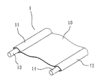
図1は軟質片体10を具えるブラインドのスラット1を示す。それは主に該軟質片体10の両側にそれぞれケースパイプ11、12を設置し、これにより二サポート棒13、14を穿入させ、こうして該軟質片体10はブラインドのスラット1を構成する。このタイプの構造には特許文献1、特許文献2、特許文献3等がある。これら構造は各種軟質片体の設置を提供し、ブラインドのスラットを組成し、これにより一般的名硬式スラットが人に与える硬くて色彩変化に乏しい印象を改善することはできるが、美観の面で、該軟式片体の選択において、非常に大きな制限を受ける。その主な原因は該軟質片体10の側辺において、必ずケースパイプ11、12を囲みミシンで縫製しなければならないことである。このため、加工が容易でない他に、その側辺の形状変化には限界がある。よって硬くて色彩変化に乏しいという欠陥を完全に克服することはできていない。
FIG. 1 shows a
本考案が解決しようとする課題は、軟質片体を組合せ堅固にサポート可能なブラインドのスラット構造を提供し、これによりブラインドのスラットは多様な組合せと変化に富んだ外形、色彩を具え、美観と商業的価値を高めることができるブラインドのスラット構造を提供することである。 The problem to be solved by the present invention is to provide a blind slat structure that can be softly supported by combining soft pieces, so that the blind slat has various combinations and varied shapes, colors, aesthetics and It is to provide a blind slat structure that can increase the commercial value.
上記課題を解決するため、本考案は下記のブラインドのスラット構造を提供する。ブラインドのスラットは少なくとも軟質片体と二サポート棒を含み、
該軟質片体の両辺側には第一穿引区と第二穿引区をそれぞれ具え、該第一穿引区と該第二穿引区は相互に平行に対応し、各間隔に予め設置する間隔距離の位置において、複数の穿引孔を設置し、これにより該二サポート棒は該軟質片体の一端から反対端まで、該第一穿引区、第二穿引区の穿引孔まで、順番に上下穿引を行い、該軟質片体をサポートし、
該軟質片体の両端位置は、それぞれ端縁を折り返し棒端定位部を形成し、しかも該棒端定位部内には二定位カバーを設置し、これにより該二サポート棒の末端は穿入定位され、
上記部品の組成により、軟質片体により構成するブラインドのスラットを提供することができ、それは多様な組合せと変化に富んだ外形、色彩を具え、美観と商業的価値を高めることができる。
In order to solve the above problems, the present invention provides the following blind slat structure. The blind slat contains at least a soft piece and two support rods,
Both sides of the soft piece are provided with a first perforated section and a second perforated section, and the first perforated section and the second perforated section correspond to each other in parallel and are set in advance at intervals. A plurality of perforation holes are provided at positions of a distance between the first support section and the second support section so that the two support rods extend from one end to the opposite end of the soft piece. Until the top and bottom are drilled in order to support the soft piece,
At both ends of the soft piece body, the ends are folded back to form a rod end localization portion, and a two localization cover is installed in the rod end localization portion, whereby the ends of the two support rods are inserted and localized. ,
The composition of the above parts can provide a blind slat composed of a soft piece, which can have various combinations, various shapes and colors, and can enhance aesthetics and commercial value.
上記本考案の軟質片体は布、或いは皮革、プラスチック、針織布により製造する。 The soft piece of the present invention is made of cloth, leather, plastic, or needle-woven cloth.
上記本考案のサポート棒は木質、或いは竹、金属材料、ガラス繊維、プラスチック材質により製造する。 The support rod of the present invention is made of wood or bamboo, metal material, glass fiber, or plastic material.
上記本考案の棒端定位部の外部にはさらに外カバー部品を嵌設し、該外カバー部品は片側に開口を具え、内部には設置空間を形成し、棒端定位部をその内に設置し、これにより該棒端定位部を設置挟持することができる。 An outer cover part is further fitted outside the rod end localization part of the present invention, the outer cover part has an opening on one side, an installation space is formed inside, and the rod end localization part is installed therein. Thus, the rod end localization portion can be installed and clamped.
請求項1の考案は、少なくとも軟質片体と二サポート棒を含み、
該軟質片体の両辺側には縦方向の第一穿引区と第二穿引区をそれぞれ具え、該第一穿引区と該第二穿引区は相互に平行に対応し、各間隔に予め設置する間隔距離の位置において複数の穿引孔を設置し、該軟質片体の両端位置にはそれぞれ棒端定位部を形成し、
該サポート棒は細長い棒体で、その両末端は該軟質片体の棒端定位部にそれぞれ嵌設することを特徴とするブラインドのスラット構造としている。
請求項2の考案は、前記棒端定位部は二定位カバーを具えることを特徴とする請求項1に記載のブラインドのスラット構造としている。
請求項3の考案は、前記棒端定位部の外部には外カバー部品を嵌設し、前記外カバー部品は片側に開口を具え、内部に向かい設置空間を形成することを特徴とする請求項1に記載のブラインドのスラット構造としている。
請求項4の考案は、前記外カバー部品の設置空間内には二定位槽を具えることを特徴とする請求項3に記載のブラインドのスラット構造としている。
The device of
On both sides of the soft piece, there are provided a first and second perforated sections in the vertical direction, the first perforated section and the second perforated section corresponding to each other in parallel, A plurality of perforation holes are installed at a position of an interval distance set in advance, and a rod end localization portion is formed at each end position of the soft piece,
The support rod is a slender rod body, and both ends thereof are blind slat structures characterized in that they are respectively fitted into the rod end positioning portions of the soft piece.
According to a second aspect of the present invention, the blind end slat structure according to the first aspect is characterized in that the rod end localization portion includes a dual localization cover.
The invention of
According to a fourth aspect of the present invention, there is provided a blind slat structure according to the third aspect of the present invention, further comprising a two-positioned tank in the installation space of the outer cover part.
上記のように、本考案は各式軟式片体を組合せブラインドのスラットを組成することができ、これにより公知のブラインドのスラットの硬くて色彩変化に乏しいという欠陥を完全に克服することができ、実用的で進歩的である。 As described above, the present invention can compose a blind slat by combining each type of soft piece, thereby completely overcoming the deficiencies of known blind slats that are hard and lack of color change, Practical and progressive.
本考案の立体分解図である図2に示すように、本考案のブラインドのスラット2は少なくとも軟質片体20と二サポート棒24、25を含む。
As shown in FIG. 2, which is a three-dimensional exploded view of the present invention, the
該軟質片体20の両辺側には縦方向の第一穿引区21と第二穿引区22をそれぞれ具える。該第一穿引区21と該第二穿引区22は相互に平行に対応し、各間隔に予め設置する間隔距離B(必要に応じて間隔距離を設定することができる)の位置において、複数の穿引孔211、221を設置する。該軟質片体20の両端位置は、それぞれ端縁230を折り返し、棒端定位部23を形成する。しかも該棒端定位部23内には開口を具える定位カバー231、232を設置する。
On both sides of the
該サポート棒24、25は細長い棒体で、その両末端241、251は該軟質片体20の二棒端定位部23の定位カバー231、232にそれぞれ嵌設する。
The
上記部品の組成により(図3〜図7参照)、先ず該二サポート棒24、25の末端241、251により、該軟質片体20の一端から反対端まで、順番に該第一穿引区21、第二穿引区22の穿引孔211、221まで、上下対応の穿引を行う。並びに、その二末端241、251により該棒端定位部23の定位カバー231、232にそれぞれ挿入(図3、8参照)し、サポート棒24、25の該軟質片体20への挿入設置を完成し、こうしてブラインドのスラット2を組成する。側面から見ると、それは上下波浪状の外形を具え、複数のブラインドのスラット2により組み立てられるブラインドAを構成する(図9参照)。該ブラインドAは全体的な外観が変化に富み、美しく、公知のブラインドのスラットに存在する欠点を確実に解決することができる。
According to the composition of the above parts (see FIGS. 3 to 7), first, the
図10、図11に示すように、本考案第二実施例は該棒端定位部23と該サポート棒24、25の固定の便のため、また同時に装飾効果を向上させるため、該棒端定位部23の外部に外カバー部品3を嵌設する。該外カバー部品3は片側に開口31を具え、内部に向かい設置空間310を形成する。該設置空間310内には二定位槽311、312を具え、これにより該棒端定位部23と該サポート棒24、25の末端241、251を設置挟持することができる。
As shown in FIGS. 10 and 11, in the second embodiment of the present invention, the rod end orientation is used for fixing the rod
上記のように、本考案は各式軟式片体を組合せブラインドのスラットを組成することができ、これにより公知のブラインドのスラットの硬くて色彩変化に乏しいという欠陥を完全に克服することができ、実用的で進歩的である。 As described above, the present invention can compose a blind slat by combining each type of soft piece, thereby completely overcoming the deficiencies of known blind slats that are hard and lack of color change, Practical and progressive.
1 ブラインドのスラット
10 軟質片体
11、12 ケースパイプ
13、14 サポート棒
2 ブラインドのスラット
20 軟質片体
21 第一穿引区
211、221 穿引孔
22 第二穿引区
230 端縁
231、232 定位カバー
24、25 サポート棒
241、251 末端
3 外カバー部品
31 開口
310 設置空間
311、312 定位槽
A ブラインド
B 間隔距離
DESCRIPTION OF
Claims (4)
該軟質片体の両辺側には縦方向の第一穿引区と第二穿引区をそれぞれ具え、該第一穿引区と該第二穿引区は相互に平行に対応し、各間隔に予め設置する間隔距離の位置において複数の穿引孔を設置し、該軟質片体の両端位置にはそれぞれ棒端定位部を形成し、
該サポート棒は細長い棒体で、その両末端は該軟質片体の棒端定位部にそれぞれ嵌設することを特徴とするブラインドのスラット構造。 Including at least a soft piece and two support rods,
On both sides of the soft piece, there are provided a first and second perforated sections in the vertical direction, the first perforated section and the second perforated section corresponding to each other in parallel, A plurality of perforation holes are installed at a position of an interval distance set in advance, and a rod end localization portion is formed at each end position of the soft piece,
A blind slat structure characterized in that the support rod is an elongated rod body, and both ends thereof are fitted into the rod end positioning portions of the soft piece.
Priority Applications (1)
| Application Number | Priority Date | Filing Date | Title |
|---|---|---|---|
| JP2008002977U JP3143420U (en) | 2008-05-09 | 2008-05-09 | Blind slat structure |
Applications Claiming Priority (1)
| Application Number | Priority Date | Filing Date | Title |
|---|---|---|---|
| JP2008002977U JP3143420U (en) | 2008-05-09 | 2008-05-09 | Blind slat structure |
Publications (1)
| Publication Number | Publication Date |
|---|---|
| JP3143420U true JP3143420U (en) | 2008-07-24 |
Family
ID=43293356
Family Applications (1)
| Application Number | Title | Priority Date | Filing Date |
|---|---|---|---|
| JP2008002977U Expired - Fee Related JP3143420U (en) | 2008-05-09 | 2008-05-09 | Blind slat structure |
Country Status (1)
| Country | Link |
|---|---|
| JP (1) | JP3143420U (en) |
Cited By (1)
| Publication number | Priority date | Publication date | Assignee | Title |
|---|---|---|---|---|
| JP5200310B1 (en) * | 2012-06-28 | 2013-06-05 | 光雄 皆川 | Heat shield sheet member and manufacturing method thereof |
-
2008
- 2008-05-09 JP JP2008002977U patent/JP3143420U/en not_active Expired - Fee Related
Cited By (1)
| Publication number | Priority date | Publication date | Assignee | Title |
|---|---|---|---|---|
| JP5200310B1 (en) * | 2012-06-28 | 2013-06-05 | 光雄 皆川 | Heat shield sheet member and manufacturing method thereof |
Similar Documents
| Publication | Publication Date | Title |
|---|---|---|
| USD853751S1 (en) | Two color mattress with a contrasting zipper strip | |
| US20160376837A1 (en) | Cordless blind assembly | |
| US20080173410A1 (en) | Slat structure for vertical window shades | |
| CN204646045U (en) | hollow sandwich curtain | |
| KR101816301B1 (en) | Wooden panel having a traditional pattern by using prefabricate-technique | |
| KR101816300B1 (en) | Wooden panel having a traditional pattern by using prefabricate-technique | |
| US20070006979A1 (en) | Venetian blind assembly | |
| CN201612474U (en) | Structure of curtain rail and cover plate | |
| US20100206493A1 (en) | Slat for venetian blind | |
| CN202594976U (en) | Three-layer glass decorative main body | |
| CN201353091Y (en) | Roman shade with pull rope decoration | |
| KR100617502B1 (en) | Inflatable tree unit | |
| US7481259B2 (en) | Half moon arch window insert | |
| JP3145547U (en) | Round bamboo panel unit | |
| CN201193474Y (en) | Shutter blade structure | |
| JP3122459U (en) | curtain | |
| JP4664829B2 (en) | Casting fence | |
| KR101382175B1 (en) | A Curtain Hanger | |
| JP6116116B2 (en) | Joinery | |
| USD570520S1 (en) | Lighting fixture | |
| KR200393412Y1 (en) | Structure of table | |
| JP2006271741A (en) | Curtain body of solar shading device | |
| JP3215936U (en) | Decorative hardware | |
| KR101223580B1 (en) | A Curtain Hanger | |
| CN203305763U (en) | Three-layered glass decoration main body provided with hollowed decoration |
Legal Events
| Date | Code | Title | Description |
|---|---|---|---|
| R150 | Certificate of patent or registration of utility model |
Free format text: JAPANESE INTERMEDIATE CODE: R150 |
|
| FPAY | Renewal fee payment (event date is renewal date of database) |
Free format text: PAYMENT UNTIL: 20110702 Year of fee payment: 3 |
|
| LAPS | Cancellation because of no payment of annual fees |