JP3143703U - Safety razor holder - Google Patents
Safety razor holder Download PDFInfo
- Publication number
- JP3143703U JP3143703U JP2008003339U JP2008003339U JP3143703U JP 3143703 U JP3143703 U JP 3143703U JP 2008003339 U JP2008003339 U JP 2008003339U JP 2008003339 U JP2008003339 U JP 2008003339U JP 3143703 U JP3143703 U JP 3143703U
- Authority
- JP
- Japan
- Prior art keywords
- replacement blade
- mounting
- blade
- replacement
- base
- Prior art date
- Legal status (The legal status is an assumption and is not a legal conclusion. Google has not performed a legal analysis and makes no representation as to the accuracy of the status listed.)
- Expired - Fee Related
Links
Images






Landscapes
- Knives (AREA)
Abstract
【課題】2枚刃の替え刃と3枚刃の替え刃とを選択的に取り付けて使用することが可能な安全かみそりのホルダーを提供する。
【解決手段】第1装着部2aは、基台部11の上面から突出して第1の替え刃の一方の係合溝に係合する爪部21と、頭部3において突出するように形成された小壁部22の外側面に設けられ、第1の替え刃の他方の係合溝に係合する係合部23とを有し、第2装着部2bは、第2の替え刃の係合アームの凹部に挿入可能に形成された小壁部22と、基台部11の上面のほぼ中央部から突出し、凹部に小壁部22を挿入した状態で第2の替え刃の本体の一方の側縁部の中央が嵌まり込んで固定するための係止部35とを有する。
【選択図】図7To provide a holder for a safety razor capable of selectively attaching and using a two-blade replacement blade and a three-blade replacement blade.
A first mounting portion 2a is formed so as to protrude from an upper surface of a base portion 11 and a claw portion 21 that engages with one engaging groove of a first replacement blade, and to protrude at a head portion 3. Provided on the outer surface of the small wall portion 22 and engaged with the other engaging groove of the first replacement blade, and the second mounting portion 2b is an engagement member of the second replacement blade. One of the main bodies of the second replacement blade with the small wall portion 22 formed so as to be insertable into the concave portion of the combined arm and the substantially wall portion 22 protruding from the substantially upper surface of the base portion 11 and the small wall portion 22 being inserted into the concave portion. There is a locking portion 35 for fitting and fixing the center of the side edge portion.
[Selection] Figure 7
Description
本考案は、頭部と柄部とが長手方向に延びる基線に沿って一体化され、2種類の替え刃を選択的に装着可能なように構成された安全かみそりのホルダーに関する。 The present invention relates to a holder for a safety razor in which a head portion and a handle portion are integrated along a base line extending in a longitudinal direction so that two types of replacement blades can be selectively attached.
従来において、頭部と柄部とが長手方向に延びる基線に沿って一体化され、頭部において基線の両側に配された装着面に替え刃を取り付けるための係合部材が設けられた形式の安全かみそりが、特開平5−123460号として提案されている(特許文献1参照)。 Conventionally, the head portion and the handle portion are integrated along a base line extending in the longitudinal direction, and an engagement member for attaching a replacement blade to the mounting surfaces arranged on both sides of the base line in the head portion is provided. A safety razor has been proposed as JP-A-5-123460 (see Patent Document 1).
また、2種類の替え刃を選択的に装着可能な安全かみそりのホルダーを、本出願人は先に特許文献2として提案した。
The applicant previously proposed as
なお、このような安全かみそりに用いられる替え刃は、長方形状のプラスチック製のケース内に1枚ないし3枚の刃体が装着され、ケースの裏面に取り付けのための係合溝や係合アームなどが設けられている。 In addition, the replacement blade used for such a safety razor has one or three blades mounted in a rectangular plastic case, and an engagement groove or an engagement arm for mounting on the back of the case. Etc. are provided.
例えば、2枚刃の替え刃として、シックスーパーII(シックジャパン株式会社)が市販され、3枚刃の替え刃として、シックトリプルエッジ(シックジャパン株式会社)、またはジレットマンハッタンスリー(ジレットジャパンインコーポレイテッド社)が市販されている(非特許文献1,2参照)。
しかし、従来において、平面視が長方形状であってその底面部において長手方向に延びて互いに対向する2つの係合溝を有する2枚刃の替え刃と、平面視が長方形状であってその底面部において中央部に凹部を有した揺動可能な係合アームを有する3枚刃の替え刃とを選択的に装着可能なように構成された安全かみそりのホルダーは存在しなかった。 However, conventionally, a two-blade replacement blade having a rectangular shape in plan view and having two engaging grooves extending in the longitudinal direction at the bottom surface portion thereof and facing each other, and a bottom surface having a rectangular shape in plan view. There is no safety razor holder configured so that a three-blade replacement blade having a swingable engaging arm having a recess in the central portion can be selectively mounted.
そのため、それぞれの替え刃を専用のホルダーに取り付けて使用しなければならず、これら2つの替え刃を交換して使用したい者にとって不便な状態が続いていた。 Therefore, each replacement blade has to be used by attaching it to a dedicated holder, and it has been inconvenient for those who want to replace these two replacement blades.
本考案は、上述の問題に鑑みてなされたもので、2枚刃の替え刃と3枚刃の替え刃とを選択的に取り付けて使用することのできる安全かみそりのホルダーを提供することを目的とする。 The present invention has been made in view of the above-described problems, and an object of the present invention is to provide a safety razor holder that can be selectively used with a two-blade replacement blade and a three-blade replacement blade. And
本考案に係る実施形態の安全かみそりのホルダーは、頭部と柄部とが長手方向に延びる基線に沿って一体化され、替え刃をその刃体の長手方向が前記基線に沿うようにして取り付けるための装着部が前記頭部に設けられてなる安全かみそりのホルダーであって、前記頭部は、その中央部において前記基線に沿って延びる基台部を有し、前記装着部には、平面視が長方形状であってその底面部において長手方向に延びて互いに対向する2つの係合溝を有する第1の替え刃を装着するための第1装着部と、平面視が長方形状であってその底面部において中央部に凹部を有した揺動可能な係合アームを有する第2の替え刃を装着するための第2装着部と、が設けられ、前記第1装着部は、前記基台部の上面から突出して前記第1の替え刃の一方の係合溝に係合する爪部と、前記基台部の側面から離れた状態で前記頭部において突出するように形成された小壁部の外側面に設けられ、前記第1の替え刃の他方の係合溝に係合する係合部と、を有し、前記第2装着部は、前記第2の替え刃の前記係合アームの前記凹部に挿入可能に形成された前記小壁部と、前記基台部の上面のほぼ中央部から突出し、前記凹部に前記小壁部を挿入した状態で前記第2の替え刃の本体の一方の側縁部の中央が嵌まり込んで固定するための係止部と、を有し、前記第1の替え刃または前記第2の替え刃が前記第1装着部または前記第2装着部に選択的に装着可能なように構成されてなる。 In the safety razor holder according to the embodiment of the present invention, the head and the handle are integrated along the base line extending in the longitudinal direction, and the replacement blade is attached so that the longitudinal direction of the blade body is along the base line. A safety razor holder in which a mounting portion for mounting is provided on the head, wherein the head has a base portion extending along the base line at a central portion thereof, and the mounting portion has a flat surface. A first mounting portion for mounting a first replacement blade having a rectangular shape and having two engaging grooves that extend in the longitudinal direction and face each other on the bottom surface thereof; A second mounting portion for mounting a second replacement blade having a swingable engaging arm having a concave portion in the central portion at the bottom portion thereof, wherein the first mounting portion is the base One of the first replacement blades protruding from the upper surface of the part A claw portion that engages with the groove, and is provided on an outer surface of a small wall portion that is formed so as to protrude from the side face of the base portion, and the other side of the first replacement blade. An engagement portion that engages with an engagement groove, and the second mounting portion is configured to be inserted into the recess of the engagement arm of the second replacement blade, and For projecting from substantially the center of the upper surface of the base portion and inserting and fixing the center of one side edge of the main body of the second replacement blade in a state where the small wall portion is inserted into the recess. The first replacement blade or the second replacement blade can be selectively mounted on the first mounting portion or the second mounting portion.
本考案によると、2枚刃の替え刃と3枚刃の替え刃とを選択的に取り付けて使用することができる。 According to the present invention, a two-blade replacement blade and a three-blade replacement blade can be selectively attached and used.
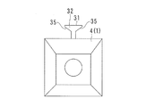
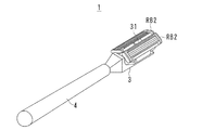
図1は本考案にかかるホルダー1の全体の平面図、図2は頭部3を拡大して示す平面図、図3は頭部3を拡大して示す右側面図、図4はホルダー1を拡大して示す正面図、図5はホルダー1を拡大して示す背面図、図6はホルダー1の正面断面図、図7は頭部3の斜視図、図8は1つの第1の替え刃を装着した状態を示す正面断面図、図9は1つの第2の替え刃を装着した状態を示す正面断面図、図10は第1の替え刃を装着するときの操作を説明するための図、図11は第2の替え刃を装着するときの操作を説明するための図、図12は2つの第1の替え刃を装着した状態を示す斜視図、図13は2つの第2の替え刃を装着した状態を示す斜視図、図14は第1の替え刃の平面図および右側面図、図15は第2の替え刃の平面図および右側面図である。
1 is a plan view of the
これらの図において、ホルダー1は、頭部3、頭部3に設けられた装着部2、および柄部4からなる。頭部3と柄部4とは、長手方向に延びる基線KSに沿って一体に形成される。
In these drawings, the
頭部3は、鋼材またはステンレス鋼などの金属材料を削りだすことにより製作される。頭部3には、その中央部において基線KSに沿って延びる基台部11が設けられている。
The
図6および図7によく示されるように、基台部11は、その断面形状が縦長の長方形であり、全体の形状は、外周面が上面111、側面112,113、端面114などに囲まれた直方体状である。なお、端面114は、基台部11の先端部の一部であり、底部に近い部分は斜めにカットされて斜面115を形成している。
As shown well in FIGS. 6 and 7, the
装着部2には、第1の替え刃RB1を装着するための第1装着部2a、および第2の替え刃RB2を装着するための第2装着部2bが形成されている。
The
第1装着部2aおよび第2装着部2bは、それぞれ、基線KSに対して左右対称な状態となるように2つずつ設けられている。つまり、装着部2には、2つの第1の替え刃RB1、または2つの第2の替え刃RB2を装着することが可能であり、または、1つの第1の替え刃RB1と1つの第2の替え刃RB2とを同時に装着することが可能である。
Two
2つの第1装着部2aおよび2つの第2装着部2bについて、それらはそれぞれ基線KSに対して対称な状態であるから、以下においては主としてそれぞれ1つのみについて説明する。
Since the two first mounting
なお、図14に示すように、第1の替え刃RB1は、平面視が長方形状であって、その底面部72において、長手方向に延びて互いに対向する2つの係合溝73a,73bが設けられている。係合溝73a,73bのいずれか一方または両方を指して、「係合溝73」と記載することがある。なお、本実施形態において、第1の替え刃RB1は、シックジャパン株式会社製またはウイルキンソン社製の2枚刃の替え刃である。
As shown in FIG. 14, the first replacement blade RB1 has a rectangular shape in plan view, and has two
図15に示すように、第2の替え刃RB2は、本体76の平面視が長方形状であって、その底面部79において、中央部に凹部78を有した揺動可能な係合アーム77が設けられている。係合アーム77は、図15(B)に示す状態が最も下方に揺動した状態であり、この状態から、図の矢印M3方向に揺動可能であり、図15(A)に示す状態が最も上方に揺動した状態である。第2の替え刃RB2の係合アーム77の下側壁の先端部には、切り欠き部77aが設けられている。なお、本実施形態において、第2の替え刃RB2は、ジレットジャパンインコーポレイテッド社の3枚刃の替え刃である。
As shown in FIG. 15, the second replaceable blade RB <b> 2 has a rectangular shape in a plan view of the
第1の替え刃RB1および第2の替え刃RB2は、いずれも本体が合成樹脂製であり、全体として適度な可撓性を有する。 Each of the first replacement blade RB1 and the second replacement blade RB2 has a main body made of a synthetic resin and has appropriate flexibility as a whole.
図2〜図8に示されるように、第1装着部2aは、基台部11の上面111から突出して第1の替え刃RB1の一方の係合溝73bに係合する爪部21と、基台部11の側面112,113から離れた状態で頭部3において突出するように形成された小壁部22の外側面221に設けられ、第1の替え刃RB1の他方の係合溝73aに係合する係合部23とを有する。
2-8, the 1st mounting
図2および図7で明らかなように、爪部21は、1つの第1装着部2aについて、基台部11の上面111の2箇所に突出して設けられている。したがって、基台部11の上面111には、その4箇所に爪部21が設けられている。
As apparent from FIGS. 2 and 7, the
図3、図6〜図8で明らかなように、係合部23は、小壁部22の外側面221の上端部の近辺に基線KSと平行に設けられた長溝24によって形成されている。つまり、小壁部22の外側面221の上端部の近辺に設けられた長溝24によって、長溝24よりも上端側の部分が係合部23となっている。
As is apparent from FIGS. 3 and 6 to 8, the
図2〜図9に示されるように、第2装着部2bは、第2の替え刃RB2の係合アーム77の凹部78に挿入可能に形成された小壁部22と、基台部11の上面111のほぼ中央部から突出し、凹部78に小壁部22を挿入した状態で第2の替え刃RB2の本体76の一方の側縁部76aの中央が嵌まり込んで固定するための係止部35とを有する。
2-9, the
すなわち、基台部11の上面111のほぼ中央部には、係止塔31が突出して設けられている。図6によく示されるように、係止塔31は、基線KSに垂直な面による断面がほぼT字形であり、天部32の下側の面が傾斜した傾斜面となっており、この傾斜面によって係止塔31が形成されている。
In other words, the
また、小壁部22は、第2の替え刃RB2の係合アーム77の凹部78に余裕を持って挿入可能な形状である。
The
次に、第1の替え刃RB1および第2の替え刃RB2の装着および取り外しの方法について説明する。 Next, a method for mounting and removing the first replacement blade RB1 and the second replacement blade RB2 will be described.
まず、ユーザが第1の替え刃RB1を装着するには、ユーザの片方の手でホルダー1を持ち、他方の手で第1の替え刃RB1を持ち、図10に示す状態とする。この状態から、図8に示すように、第1の替え刃RB1の係合溝73aと小壁部22の係合部23とを係合させ、かつ、第1の替え刃RB1の係合溝73bと2つの爪部21のうちの端部に近い側の爪部21とを係合させ、その状態で、第1の替え刃RB1を図の矢印M1方向にスライド移動させながら、係合溝73bを他方の爪部21に係合させ、スライド端まで移動させる。
First, in order to mount the first replacement blade RB1 by the user, the user holds the
この状態では、第1の替え刃RB1は、その係合溝73a,bが2つの爪部21および係合部23と係合し、これによってしっかりと固定される。
In this state, the first replacement blade RB1 has its
なお、この状態において、第1の替え刃RB1は係止塔31と接触しないが、第1の替え刃RB1の外縁部が係止部35と接触して保持されるようにしてもよい。また、第1の替え刃RB1の係合溝73bと1つの爪部21とが係合した状態では、その爪部21と係合部23との位置が基線KSの方向に対してずれた位置にあるので、第1の替え刃RB1の姿勢を容易に変更することができ、したがってこの状態では第1の替え刃RB1をしっかりと固定した状態とはならない。
In this state, the first replacement blade RB1 does not contact the locking
2つの第2装着部2aにそれぞれ第1の替え刃RB1を装着すると、図12に示す状態となる。
When the first replacement blade RB1 is mounted on each of the two
また、第1の替え刃RB1を取り外すときは、第1の替え刃RB1の本体71をユーザが指で挟み、図10の矢印M2方向へスライド移動させて取り外せばよい。
Further, when removing the first replaceable blade RB1, the user can hold the
次に、ユーザが第2の替え刃RB2を装着するには、ユーザの片方の手でホルダー1を持ち、他方の手で第2の替え刃RB2を持ち、図11に示す状態とする。この状態から、図9に示すように、第2装着部2bに第2の替え刃RB2を装着した状態とする。この状態では、係合アーム77に設けられた切り欠き部77aの端面が、基台部11と小壁部22との間にある頭部3での底部から若干膨らむように形成された膨出面部25の表面に当接する。
Next, in order to mount the second replacement blade RB2 by the user, the user holds the
また、小壁部22の先端部は、係合アーム77の凹部78の内周面に当接し、これによって係合アーム77が図9における右方向へのそれ以上の回転移動が規制された状態となる。この状態において、第2の替え刃RB2の自由状態では、第2の替え刃RB2の本体76の側縁部76aが係止塔31の天部32と干渉し、そのため側縁部76aは係止部35にまで到達しないのであるが、ユーザが指で本体76の表面を押さえ、側縁部76aを係止部35に押し込むようにすると、第2の替え刃RB2の可撓性によって全体が若干撓み、側縁部76aが係止部35に押し込まれ、その状態で係止される。これによって、第2の替え刃RB2は、第2装着部2bにしっかりと固定される。
Further, the distal end portion of the
したがって、2つの第2装着部2bにそれぞれ第2の替え刃RB2を装着すると、図13に示す状態となる。
Therefore, when the second replacement blade RB2 is mounted on each of the two
また、第2の替え刃RB2を取り外すときは、第2の替え刃RB2の本体76をユーザが指で挟んで外側へ引っ張ることにより、第2の替え刃RB2の全体が撓んで側縁部76aが係止部35から抜け出す。
Further, when removing the second replacement blade RB2, when the user holds the
上に述べたように、本実施形態のホルダー1によると、2枚刃の第1の替え刃RB1と3枚刃の第2の替え刃RB2とを選択的に取り付けて使用することができる。第1の替え刃RB1および第2の替え刃RB2をそれぞれ2つずつ取り付けることができるので、長い時間に渡って交換することなく使用できる。また、第1装着部2aおよび第2装着部2bが、それぞれ基線KSを基線KSに対して対称な状態となるように2つずつ設けられているので、2つの第1の替え刃RB1または2つの第2の替え刃RB2を取り付けることにより、押しによる剃りと引きによる剃りとを自由に使い分けることができる。
As described above, according to the
また、第1装着部2aおよび第2装着部2bのいずれか一方に第1の替え刃RB1を装着し、他方に第2の替え刃RB2を装着することにより、使い勝手に応じて、または剃りの仕上がり程度に応じて、第1の替え刃RB1と第2の替え刃RB2とを自在に使い分けることができる。
Further, by mounting the first replacement blade RB1 on one of the first mounting
また、ユーザにもよるが、第1の替え刃RB1および第2の替え刃RB2について、その全体が均等に使われないことがある。つまり、ホルダー1に取り付けられた替え刃RBの先端側がよく使用され、先端側がよく摩耗する。その場合に、そのような替え刃RBを、第1装着部2aから第2装着部2bに、またはこの逆に付け替えることにより、摩耗していない側を使用することができ、替え刃RBの全体を万遍なく効率的に利用することができ、経済的である。
Depending on the user, the entire first replacement blade RB1 and second replacement blade RB2 may not be used evenly. That is, the tip side of the replacement blade RB attached to the
上の実施形態において、第1装着部2a、第2装着部2b、頭部3、またはホルダー1の全体または各部の構造、形状、寸法、個数、材質などは、本考案の趣旨に沿って適宜変更することができる。
In the above embodiment, the structure, shape, dimensions, number, material, etc. of the whole or each part of the first mounting
1 ホルダー
2 装着部
2a 第1装着部
2b 第2装着部
3 頭部
4 柄部
11 基台部
21 爪部
22 小壁部
23 係合部
24 長溝
31 係止塔
35 係止部
KS 基線
RB1 第1の替え刃(替え刃、3枚刃の替え刃)
RB2 第2の替え刃(替え刃、2枚刃の替え刃)
76 係合溝
77 係合アーム
78 凹部
76a 側縁部
DESCRIPTION OF
RB2 2nd replacement blade (replacement blade, 2 blade replacement blade)
76
Claims (5)
前記頭部は、
その中央部において前記基線に沿って延びる基台部を有し、
前記装着部には、
平面視が長方形状であってその底面部において長手方向に延びて互いに対向する2つの係合溝を有する第1の替え刃を装着するための第1装着部と、
平面視が長方形状であってその底面部において中央部に凹部を有した揺動可能な係合アームを有する第2の替え刃を装着するための第2装着部と、が設けられ、
前記第1装着部は、
前記基台部の上面から突出して前記第1の替え刃の一方の係合溝に係合する爪部と、
前記基台部の側面から離れた状態で前記頭部において突出するように形成された小壁部の外側面に設けられ、前記第1の替え刃の他方の係合溝に係合する係合部と、を有し、
前記第2装着部は、
前記第2の替え刃の前記係合アームの前記凹部に挿入可能に形成された前記小壁部と、
前記基台部の上面のほぼ中央部から突出し、前記凹部に前記小壁部を挿入した状態で前記第2の替え刃の本体の一方の側縁部の中央が嵌まり込んで固定するための係止部と、を有し、
前記第1の替え刃または前記第2の替え刃が前記第1装着部または前記第2装着部に選択的に装着可能なように構成されてなる、
ことを特徴とする安全かみそりのホルダー。 The head and the handle are integrated along a base line extending in the longitudinal direction, and a mounting part for attaching the replacement blade so that the longitudinal direction of the blade body is along the base line is provided on the head. A safety razor holder,
The head is
It has a base part extending along the base line in the central part,
In the mounting part,
A first mounting portion for mounting a first replacement blade that has a rectangular shape in plan view and has two engaging grooves that extend in the longitudinal direction and face each other on the bottom surface portion thereof;
A second mounting portion for mounting a second replacement blade having a swingable engaging arm having a rectangular shape in plan view and having a recess in the central portion at the bottom surface thereof;
The first mounting part is
A claw portion that protrudes from the upper surface of the base portion and engages with one engagement groove of the first replacement blade;
An engagement that is provided on the outer surface of the small wall portion that is formed so as to protrude from the side face of the base portion in a state of being separated from the side surface of the base portion, and engages with the other engagement groove of the first replacement blade. And
The second mounting part is
The small wall portion formed so as to be insertable into the concave portion of the engagement arm of the second replacement blade;
For projecting from substantially the center of the upper surface of the base portion and inserting and fixing the center of one side edge of the main body of the second replacement blade in a state where the small wall portion is inserted into the recess. A locking portion,
The first replacement blade or the second replacement blade is configured to be selectively mountable on the first mounting portion or the second mounting portion.
A safety razor holder characterized by that.
請求項1記載の安全かみそりのホルダー。 The claw portions are provided at two locations on the upper surface of the base portion.
The safety razor holder according to claim 1.
請求項1または2記載の安全かみそりのホルダー。 The engaging portion is formed by a long groove provided in parallel with the base line in the vicinity of the upper end portion of the outer surface of the small wall portion.
The holder for the safety razor according to claim 1 or 2.
請求項1ないし3のいずれかに記載の安全かみそりのホルダー。 The locking portion has a substantially T-shaped cross section by a plane perpendicular to the base line.
The safety razor holder according to any one of claims 1 to 3.
Priority Applications (1)
| Application Number | Priority Date | Filing Date | Title |
|---|---|---|---|
| JP2008003339U JP3143703U (en) | 2008-05-22 | 2008-05-22 | Safety razor holder |
Applications Claiming Priority (1)
| Application Number | Priority Date | Filing Date | Title |
|---|---|---|---|
| JP2008003339U JP3143703U (en) | 2008-05-22 | 2008-05-22 | Safety razor holder |
Publications (1)
| Publication Number | Publication Date |
|---|---|
| JP3143703U true JP3143703U (en) | 2008-07-31 |
Family
ID=43293612
Family Applications (1)
| Application Number | Title | Priority Date | Filing Date |
|---|---|---|---|
| JP2008003339U Expired - Fee Related JP3143703U (en) | 2008-05-22 | 2008-05-22 | Safety razor holder |
Country Status (1)
| Country | Link |
|---|---|
| JP (1) | JP3143703U (en) |
-
2008
- 2008-05-22 JP JP2008003339U patent/JP3143703U/en not_active Expired - Fee Related
Similar Documents
| Publication | Publication Date | Title |
|---|---|---|
| CN104870149B (en) | razor | |
| ES2784706T3 (en) | Comb attachment for hair clippers | |
| US8499459B2 (en) | Shaving blade unit and shaver having such a blade unit | |
| CN107107358B (en) | Shaving blade cartridge and shaver comprising same | |
| CN102166757B (en) | electric razor | |
| WO2007116356A3 (en) | Cutting members for shaving razors | |
| JP5095163B2 (en) | Hand tools | |
| JP5390694B2 (en) | Knife | |
| KR20180088899A (en) | Shaver and shaving cartridge | |
| GB2532844A (en) | Razor module | |
| CN108367447A (en) | Razor head | |
| US20070204471A1 (en) | Knife with disposable and interchangeable blade | |
| JP3143703U (en) | Safety razor holder | |
| CN101376245A (en) | Handle of cutter | |
| US20160346941A1 (en) | Knife assembly | |
| JP4290439B2 (en) | Safety razor holder | |
| JP4766419B2 (en) | Knife | |
| JP2007061429A (en) | Medical knife | |
| JP3213733U (en) | Cutting instrument | |
| JP2006280490A (en) | Hair cutter | |
| JP3182441U (en) | Replacement knife | |
| CN217072451U (en) | Shank component of cutter and cutter | |
| JP4346516B2 (en) | Blade sharpener | |
| JP3137886U (en) | The grip of the blade | |
| JP4742284B2 (en) | razor |
Legal Events
| Date | Code | Title | Description |
|---|---|---|---|
| R150 | Certificate of patent or registration of utility model |
Free format text: JAPANESE INTERMEDIATE CODE: R150 |
|
| FPAY | Renewal fee payment (event date is renewal date of database) |
Free format text: PAYMENT UNTIL: 20110709 Year of fee payment: 3 |
|
| LAPS | Cancellation because of no payment of annual fees |