JP3143708U - Light bar fixing structure and its series connection structure - Google Patents
Light bar fixing structure and its series connection structure Download PDFInfo
- Publication number
- JP3143708U JP3143708U JP2008003354U JP2008003354U JP3143708U JP 3143708 U JP3143708 U JP 3143708U JP 2008003354 U JP2008003354 U JP 2008003354U JP 2008003354 U JP2008003354 U JP 2008003354U JP 3143708 U JP3143708 U JP 3143708U
- Authority
- JP
- Japan
- Prior art keywords
- polygonal
- light bar
- light
- fixing
- block
- Prior art date
- Legal status (The legal status is an assumption and is not a legal conclusion. Google has not performed a legal analysis and makes no representation as to the accuracy of the status listed.)
- Expired - Fee Related
Links
Images




Classifications
-
- F—MECHANICAL ENGINEERING; LIGHTING; HEATING; WEAPONS; BLASTING
- F21—LIGHTING
- F21V—FUNCTIONAL FEATURES OR DETAILS OF LIGHTING DEVICES OR SYSTEMS THEREOF; STRUCTURAL COMBINATIONS OF LIGHTING DEVICES WITH OTHER ARTICLES, NOT OTHERWISE PROVIDED FOR
- F21V21/00—Supporting, suspending, or attaching arrangements for lighting devices; Hand grips
- F21V21/02—Wall, ceiling, or floor bases; Fixing pendants or arms to the bases
-
- F—MECHANICAL ENGINEERING; LIGHTING; HEATING; WEAPONS; BLASTING
- F21—LIGHTING
- F21S—NON-PORTABLE LIGHTING DEVICES; SYSTEMS THEREOF; VEHICLE LIGHTING DEVICES SPECIALLY ADAPTED FOR VEHICLE EXTERIORS
- F21S2/00—Systems of lighting devices, not provided for in main groups F21S4/00 - F21S10/00 or F21S19/00, e.g. of modular construction
- F21S2/005—Systems of lighting devices, not provided for in main groups F21S4/00 - F21S10/00 or F21S19/00, e.g. of modular construction of modular construction
-
- F—MECHANICAL ENGINEERING; LIGHTING; HEATING; WEAPONS; BLASTING
- F21—LIGHTING
- F21S—NON-PORTABLE LIGHTING DEVICES; SYSTEMS THEREOF; VEHICLE LIGHTING DEVICES SPECIALLY ADAPTED FOR VEHICLE EXTERIORS
- F21S4/00—Lighting devices or systems using a string or strip of light sources
- F21S4/20—Lighting devices or systems using a string or strip of light sources with light sources held by or within elongate supports
- F21S4/28—Lighting devices or systems using a string or strip of light sources with light sources held by or within elongate supports rigid, e.g. LED bars
-
- F—MECHANICAL ENGINEERING; LIGHTING; HEATING; WEAPONS; BLASTING
- F21—LIGHTING
- F21S—NON-PORTABLE LIGHTING DEVICES; SYSTEMS THEREOF; VEHICLE LIGHTING DEVICES SPECIALLY ADAPTED FOR VEHICLE EXTERIORS
- F21S8/00—Lighting devices intended for fixed installation
- F21S8/03—Lighting devices intended for fixed installation of surface-mounted type
- F21S8/033—Lighting devices intended for fixed installation of surface-mounted type the surface being a wall or like vertical structure, e.g. building facade
- F21S8/037—Lighting devices intended for fixed installation of surface-mounted type the surface being a wall or like vertical structure, e.g. building facade for mounting in a corner, i.e. between adjacent walls or wall and ceiling
-
- F—MECHANICAL ENGINEERING; LIGHTING; HEATING; WEAPONS; BLASTING
- F21—LIGHTING
- F21V—FUNCTIONAL FEATURES OR DETAILS OF LIGHTING DEVICES OR SYSTEMS THEREOF; STRUCTURAL COMBINATIONS OF LIGHTING DEVICES WITH OTHER ARTICLES, NOT OTHERWISE PROVIDED FOR
- F21V21/00—Supporting, suspending, or attaching arrangements for lighting devices; Hand grips
- F21V21/08—Devices for easy attachment to any desired place, e.g. clip, clamp, magnet
- F21V21/088—Clips; Clamps
-
- F—MECHANICAL ENGINEERING; LIGHTING; HEATING; WEAPONS; BLASTING
- F21—LIGHTING
- F21S—NON-PORTABLE LIGHTING DEVICES; SYSTEMS THEREOF; VEHICLE LIGHTING DEVICES SPECIALLY ADAPTED FOR VEHICLE EXTERIORS
- F21S8/00—Lighting devices intended for fixed installation
- F21S8/03—Lighting devices intended for fixed installation of surface-mounted type
- F21S8/033—Lighting devices intended for fixed installation of surface-mounted type the surface being a wall or like vertical structure, e.g. building facade
-
- F—MECHANICAL ENGINEERING; LIGHTING; HEATING; WEAPONS; BLASTING
- F21—LIGHTING
- F21S—NON-PORTABLE LIGHTING DEVICES; SYSTEMS THEREOF; VEHICLE LIGHTING DEVICES SPECIALLY ADAPTED FOR VEHICLE EXTERIORS
- F21S8/00—Lighting devices intended for fixed installation
- F21S8/04—Lighting devices intended for fixed installation intended only for mounting on a ceiling or the like overhead structures
-
- F—MECHANICAL ENGINEERING; LIGHTING; HEATING; WEAPONS; BLASTING
- F21—LIGHTING
- F21V—FUNCTIONAL FEATURES OR DETAILS OF LIGHTING DEVICES OR SYSTEMS THEREOF; STRUCTURAL COMBINATIONS OF LIGHTING DEVICES WITH OTHER ARTICLES, NOT OTHERWISE PROVIDED FOR
- F21V7/00—Reflectors for light sources
- F21V7/0008—Reflectors for light sources providing for indirect lighting
-
- F—MECHANICAL ENGINEERING; LIGHTING; HEATING; WEAPONS; BLASTING
- F21—LIGHTING
- F21W—INDEXING SCHEME ASSOCIATED WITH SUBCLASSES F21K, F21L, F21S and F21V, RELATING TO USES OR APPLICATIONS OF LIGHTING DEVICES OR SYSTEMS
- F21W2131/00—Use or application of lighting devices or systems not provided for in codes F21W2102/00-F21W2121/00
- F21W2131/30—Lighting for domestic or personal use
- F21W2131/301—Lighting for domestic or personal use for furniture
-
- F—MECHANICAL ENGINEERING; LIGHTING; HEATING; WEAPONS; BLASTING
- F21—LIGHTING
- F21W—INDEXING SCHEME ASSOCIATED WITH SUBCLASSES F21K, F21L, F21S and F21V, RELATING TO USES OR APPLICATIONS OF LIGHTING DEVICES OR SYSTEMS
- F21W2131/00—Use or application of lighting devices or systems not provided for in codes F21W2102/00-F21W2121/00
- F21W2131/40—Lighting for industrial, commercial, recreational or military use
- F21W2131/405—Lighting for industrial, commercial, recreational or military use for shop-windows or displays
-
- F—MECHANICAL ENGINEERING; LIGHTING; HEATING; WEAPONS; BLASTING
- F21—LIGHTING
- F21Y—INDEXING SCHEME ASSOCIATED WITH SUBCLASSES F21K, F21L, F21S and F21V, RELATING TO THE FORM OR THE KIND OF THE LIGHT SOURCES OR OF THE COLOUR OF THE LIGHT EMITTED
- F21Y2115/00—Light-generating elements of semiconductor light sources
- F21Y2115/10—Light-emitting diodes [LED]
-
- H—ELECTRICITY
- H01—ELECTRIC ELEMENTS
- H01R—ELECTRICALLY-CONDUCTIVE CONNECTIONS; STRUCTURAL ASSOCIATIONS OF A PLURALITY OF MUTUALLY-INSULATED ELECTRICAL CONNECTING ELEMENTS; COUPLING DEVICES; CURRENT COLLECTORS
- H01R25/00—Coupling parts adapted for simultaneous co-operation with two or more identical counterparts, e.g. for distributing energy to two or more circuits
- H01R25/14—Rails or bus-bars constructed so that the counterparts can be connected thereto at any point along their length
- H01R25/145—Details, e.g. end pieces or joints
Landscapes
- Engineering & Computer Science (AREA)
- General Engineering & Computer Science (AREA)
- Architecture (AREA)
- Fastening Of Light Sources Or Lamp Holders (AREA)
- Non-Portable Lighting Devices Or Systems Thereof (AREA)
- Connection Of Plates (AREA)
Abstract
【課題】取付容易で直列接続可能な発光ダイオードライトバーを提供する。
【解決手段】多角形固定座1は、底辺11、その両端から屈曲して延長された斜辺12、12´、斜辺12、12´の両端から屈曲手延長された直辺13、13´により多角形ライトバーを収用する多角形を構成し、直辺13、13´両端にライトバーを掛止する係着部131、131´を設ける。底辺、斜辺にボルトを通す穿孔111,121を、係着部には切欠きを設けて取付け角度を変更する。ライトバーの両端部を封止する封止端部3に対して該封止端部と接続する電力接続器により複数のライトバーを電気的に直列接続する。
【選択図】図1A light-emitting diode light bar that can be easily mounted and connected in series is provided.
A polygonal fixed seat 1 includes a base 11, a hypotenuse 12 and 12 'bent and extended from both ends thereof, and a straight side 13 and 13' bent and extended from both ends of the hypotenuses 12 and 12 '. Polygons that take up the rectangular light bars are formed, and engaging portions 131 and 131 ′ for hooking the light bars are provided at both ends of the straight sides 13 and 13 ′. The mounting angle is changed by providing perforations 111 and 121 for passing bolts through the bottom and oblique sides and notches in the engaging portion. A plurality of light bars are electrically connected in series to a sealed end 3 that seals both ends of the light bar by a power connector connected to the sealed end.
[Selection] Figure 1
Description
本考案は、照明器具に関し、特に、ライトバー(light bar)の固定構造および直列接続構造に関する。 The present invention relates to a luminaire, and more particularly, to a light bar fixing structure and a series connection structure.
発光ダイオードは、小型、長寿命、低消費電力、速い応答速度、優れた耐衝撃性などの特徴を有する。そのため、従来の電球、小型蛍光管または冷陰極管の発光デバイスに代わり、照明器具やバックライト光源に広汎に用いられている。発光ダイオードが照明器具やバックライト光源に用いられる場合、照明器具やバックライト光源の必要に応じて回路基板が正方形または長方形に設計される。例えば、回路基板が長方形である場合、複数の発光ダイオードが長方形の回路基板上に半田付けされてライトバー(light bar)が形成される。この発光ダイオードライトバー(LED light bar)がLCD液晶ディスプレイのバックライト光源に用いられた場合、発光ダイオードライトバーは、従来の冷陰極管に代わり、LCD液晶ディスプレイの導光板の周囲に直接装着される。照明器具や展示用照明に用いられる場合は、事前に発光ダイオードライトバーが装着された長方形の固定座が壁または展示棚内壁に固定されるため、ダイオードライトバーからの光線は、展示品に直接照射される。 The light emitting diode has features such as small size, long life, low power consumption, fast response speed, and excellent impact resistance. For this reason, it is widely used in lighting fixtures and backlight sources instead of conventional light-emitting devices such as light bulbs, small fluorescent tubes or cold cathode tubes. When a light emitting diode is used for a lighting fixture or a backlight light source, the circuit board is designed to be square or rectangular according to the needs of the lighting fixture or the backlight light source. For example, when the circuit board is rectangular, a plurality of light emitting diodes are soldered onto the rectangular circuit board to form a light bar. When the LED light bar is used as a backlight source of an LCD liquid crystal display, the light emitting diode light bar is mounted directly around the light guide plate of the LCD liquid crystal display instead of the conventional cold cathode tube. The When used for lighting fixtures or display lighting, a rectangular fixed seat with a light-emitting diode light bar attached in advance is fixed to the wall or the inner wall of the exhibition shelf, so that the light from the diode light bar is directly applied to the exhibit. Irradiated.
長方形の固定座が壁または展示棚内壁に固定されると、発光ダイオードライトバーは、一定の角度に固定されているため、照射角度を調節することができなかった。また、複数の発光ダイオードライトバーが必要な時は、それぞれの発光ダイオードライトバー間の電力入力は、配線によりすべての発光ダイオードライトバーに配分された。このような配線方法は、時間および手間が掛かり、1本の導線が接触不良を起こしたり切断されたりすると、後続の発光ダイオードライトバーは、点灯することができなかったり破損してしまったりした。このため、発光ダイオードライトバーを取り外して修理したり配線を再び接続したり、修理において大変手間が掛かった。
本考案の目的は、壁または展示棚内壁に発光ダイオードライトバーを容易に固定することができ、電力接続器を用いて複数の発光ダイオードライトバーを直列接続し、取り外し交換が容易なライトバー固定構造を提供することにある。 The purpose of the present invention is to easily fix the light-emitting diode light bar on the wall or the inner wall of the display shelf, connect the light-emitting diode light bars in series using a power connector, and fix the light bar for easy removal and replacement To provide a structure.
上述の目的を達成するため、本考案は、新規なライトバーを提供する。本考案のライトバーは、多角形固定座、多角形ライトバーおよび封止端部を具える。多角形固定座は、金属またはプラスチックの材料からなる断面五角形または六角形の固定座である。多角形固定座は、底辺を有し、底辺の両端から屈曲して延長した斜辺を形成し、斜辺の両端から屈曲して延長した直辺を形成し、直辺の両端に内側に突起する係着部を設ける。底辺、斜辺、直辺により内側に多角形ライトバーを収納する多角形固定座を形成する。また、底辺および斜辺は、穿孔をそれぞれ設ける。係着部には、切欠部が設けられている。穿孔および切欠部は、ネジにより角形固定座を貫通してキャリアに螺着するのに用いられると共に、多角形固定座の方向の調節に用いられる。 To achieve the above object, the present invention provides a novel light bar. The light bar of the present invention comprises a polygonal fixed seat, a polygonal light bar and a sealed end. The polygonal fixing seat is a pentagonal or hexagonal fixing seat made of a metal or plastic material. The polygonal fixed seat has a base, forms an oblique side that is bent and extended from both ends of the base, forms a straight side that is bent and extended from both ends of the oblique side, and projects inwardly at both ends of the right side. A landing part is provided. A polygonal fixed seat for accommodating the polygonal light bar is formed on the inner side by the base, the oblique side, and the straight side. Further, perforations are provided on the bottom side and the oblique side, respectively. The engaging portion is provided with a notch. The perforations and notches are used to thread the square fixed seat and screw it onto the carrier with screws and to adjust the orientation of the polygonal fixed seat.
封止端部は、ゴムまたはプラスチックの材料からなる。封止端部は、板状の封鎖ブロックを有し、封鎖ブロックの一方の端部に円柱状の接合部および凸ブロックを凸設している。凸ブロックの断面の形状は、収納凹部、嵌溝および開口を設けた多角形ライトバーの断面形状と同じである。封止端部と多角形座体とが装着される際、接合部は、長溝に挿着される。凸ブロックは、収納凹部、嵌溝および開口の中に挿着される。封鎖ブロックのもう一方の側面には、位置決め孔および挿着孔が設けられ、挿着孔は、凸ブロックの内部まで延伸している。挿着孔は、電力入力のため、内部にピン状のリード線および片状のリード線を配置している。 The sealed end is made of a rubber or plastic material. The sealing end portion has a plate-like blockade block, and a cylindrical joint portion and a convex block are projected from one end portion of the blockade block. The cross-sectional shape of the convex block is the same as the cross-sectional shape of the polygonal light bar provided with the storage recess, the fitting groove and the opening. When the sealing end and the polygonal seat are attached, the joint is inserted into the long groove. The convex block is inserted into the storage concave portion, the fitting groove, and the opening. A positioning hole and an insertion hole are provided on the other side surface of the blocking block, and the insertion hole extends to the inside of the convex block. The insertion hole has a pin-like lead wire and a piece-like lead wire disposed therein for power input.
電力接続器は、多角形の中間接続ブロックを有し、中間接続ブロックは、両方の側面に延伸した円形の凸柱を有し、凸柱は、延伸した中空柱を有し、中空柱は、金属電極に包まれ、内部にもう1つの金属電極を有する。凸柱の上方で、中間接続ブロック1上に円柱状の位置決めがある。
The power connector has a polygonal intermediate connection block, the intermediate connection block has a circular convex column extending on both sides, the convex column has an extended hollow column, and the hollow column is It is wrapped in a metal electrode and has another metal electrode inside. There is a cylindrical positioning on the
本考案のライトバーの固定構造および直列接続構造は、固定構造により自由な角度で壁または展示棚内壁に発光ダイオードライトバーを容易に固定し、照射方向を自在に調節することができる。また、電力接続器を用いて複数の発光ダイオードライトバーを直列接続するため、故障が発生した場合でも、迅速に取り外し交換ができる。 The light bar fixing structure and the serial connection structure of the present invention can easily fix the light emitting diode light bar to the wall or the inner wall of the display shelf at a free angle by the fixing structure, and freely adjust the irradiation direction. In addition, since a plurality of light emitting diode light bars are connected in series using a power connector, even if a failure occurs, it can be quickly removed and replaced.
以下、本考案の第一の実施形態を図面に基づいて説明する。図1は、本考案の一実施形態によるライトバーおよび固定構造を示す分解斜視図である。図2は、本考案の一実施形態によるライトバーおよび固定構造を示す斜視図である。図1および図2に示すように、本考案の一実施形態によるライトバー構造は、多角形固定座1、多角形ライトバー2および封止端部3を具える。
Hereinafter, a first embodiment of the present invention will be described with reference to the drawings. FIG. 1 is an exploded perspective view illustrating a light bar and a fixing structure according to an embodiment of the present invention. FIG. 2 is a perspective view illustrating a light bar and a fixing structure according to an embodiment of the present invention. As shown in FIGS. 1 and 2, the light bar structure according to an embodiment of the present invention includes a
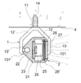
多角形固定座1は、金属またはプラスチックの材料からなる五角形または六角形の固定座である。多角形固定座1は、底辺11を有し、底辺11の両側端から屈曲して斜辺12、12´を延長し、さらに斜辺12、12´の両端から屈曲して直辺13、13´を延長して形成し、直辺13、13´のそれぞれの端部に内側に突起する係着部131、131´を形成する。これら底辺11、斜辺12、12´、直辺13、13´は、内側に多角形ライトバー2を収納する多角形固定座1を形成する。また、底辺11および斜辺12は、穿孔111、121´をそれぞれ設け、また、係着部131には、切欠部132が設けられている。穿孔111、121´および切欠部132は、ネジ14により多角形固定座1を貫通してキャリアに螺着するのに用いられるほか、多角形固定座1の方向の調節に用いられる。本実施形態においては、ネジ14を用いて多角形固定座1をキャリアに螺着しているが、両面接着テープまたはベルクロを用いて多角形固定座1をキャリアに固着してもよい。
The
多角形ライトバー2は、アルミニウム押出成形による多角形座体21を有し、多角形座体21の外部に長溝22が設けられ、多角形座体21の内部には相対して凹字型の収納凹部23が設けられている。収納凹部23は、複数の発光ダイオード25を配置する回路基板24を収納する。収納凹部23の側方の開口部の近くに一対の嵌溝26、26´が設けられ、嵌溝26、26´には、ディフューザ27を嵌着する。ディフューザ27には、発光ダイオード25の発生した光線を照射する複数の開口28が設けられている。
The
封止端部3は、ゴムまたはプラスチックの材料からなる。封止端部3は、板状の封鎖ブロック31を有し、封鎖ブロック31の一方の端部に円柱状の接合部32および凸ブロック33を凸設している。凸ブロック33の断面の形状は、収納凹部23、嵌溝26、26´および開口を具える断面形状と同じである。封止端部3と多角形座体21とが装着される際、接合部32は、長溝22に挿着される。凸ブロック33は、収納凹部23、嵌溝26、26´および開口の中に挿着される。封鎖ブロック31のもう一方の側面には、位置決め孔34および挿着孔35が設けられ、挿着孔35は、凸ブロック33の内部まで延伸している。挿着孔35は、電力入力のため、内部にピン状のリード線36および片状のリード線37を配置している。
The sealing
図3は、本考案の一実施形態によるライトバーの第1の使用状態を示す断面図である。図3に示すように、本考案の一実施形態による多角形ライトバー2は、使用時において、多角形固定座1の底辺11の穿孔111をネジ14で貫通して多角形固定座1をキャリア4上に螺着する。キャリア4は、壁または棚である。多角形固定座1が螺着されると、多角形固定座1の開口部は、下を向く。そして、多角形ライトバー2が多角形固定座1の開口部に沿って挿入されると、多角形ライトバー2が多角形固定座1に装着され、多角形ライトバー2が発生する光線を下に向けて照射する。照射方向を調整する場合は、ネジ14を外して次のようにして装着し直せば、多角形ライトバー2の照射方向を調節することができる。
FIG. 3 is a cross-sectional view illustrating a first usage state of the light bar according to an embodiment of the present invention. As shown in FIG. 3, the
図4は、本考案の一実施形態によるライトバーの第2の使用状態を示す断面図である。図4に示すように、本考案の一実施形態による多角形ライトバー2は、使用時において、多角形固定座1の斜辺12´の穿孔121´をネジ14で貫通して多角形固定座1をキャリア4上に螺着する。多角形固定座1が螺着されると、多角形固定座1の開口部は、右を向く。そして、多角形ライトバー2が多角形固定座1の開口部に沿って挿入されると、多角形ライトバー2が多角形固定座1に装着され、多角形ライトバー2が発生する光線を右下に向けて照射する。照射方向を調整する場合は、また、ネジ14を外して次のようにして装着し直せば、多角形ライトバー2の照射方向を調節することができる。
FIG. 4 is a cross-sectional view illustrating a second usage state of the light bar according to an embodiment of the present invention. As shown in FIG. 4, the polygonal
図5は、本考案の一実施形態によるライトバーの第3の使用状態を示す断面図である。図5に示すように、本考案の一実施形態による多角形ライトバー2は、使用時において、多角形固定座1の斜辺12´の穿孔121´をネジ14で貫通して多角形固定座1をキャリア4上に螺着する。多角形固定座1が螺着されると、多角形固定座1の開口部は、左下を向く。そして、多角形ライトバー2が多角形固定座1の開口部に沿って挿入されると、多角形ライトバー2が多角形固定座1に装着され、多角形ライトバー2が発生する光線を左に向けて照射する。照射方向を調整する場合は、さらに、次のようにしてネジ14を外して装着し直せば、多角形ライトバー2の照射方向を調節することができる。
FIG. 5 is a cross-sectional view illustrating a third usage state of the light bar according to an embodiment of the present invention. As shown in FIG. 5, the polygonal
図6は、本考案の一実施形態によるライトバーの第4の使用状態を示す断面図である。図7は、本考案の一実施形態によるライトバーの第5の使用状態を示す断面図である。図6および図7に示すように、本考案の一実施形態による多角形ライトバー2は、使用時において、多角形固定座1の斜辺12´の穿孔121´をネジ14で貫通して多角形固定座1をキャリア4上に螺着する。多角形固定座1が螺着されると、多角形固定座1の開口部は、下を向く。そして、多角形ライトバー2が多角形固定座1の開口部に沿って挿入されると、多角形ライトバー2が多角形固定座1に装着される。照射方向を調整する場合は、多角形ライトバー2を外してさらに、次のようにして多角形固定座1に装着し直せば、多角形ライトバー2の照射方向を調節することができる(図7参照)。
FIG. 6 is a cross-sectional view illustrating a fourth usage state of the light bar according to the embodiment of the present invention. FIG. 7 is a cross-sectional view illustrating a fifth usage state of the light bar according to the embodiment of the present invention. As shown in FIGS. 6 and 7, the polygonal
図8は、本考案の一実施形態によるライトバーの第6の使用状態を示す断面図である。図8に示すように、本考案の一実施形態による多角形ライトバー2は、使用時において、多角形固定座1の斜辺12´の穿孔121´をネジ14で貫通して多角形固定座1をキャリア4上に螺着する。多角形固定座1が螺着されると、多角形固定座1の開口部は、下を向く。そして、多角形ライトバー2が多角形固定座1の開口部に沿って挿入されると、多角形ライトバー2が多角形固定座1に装着される。多角形ライトバー2は、光線をキャリア4の壁面に照射し、壁面により照射する場所へ光線を反射させる。光線を照射する場所を調節するため、多角形ライトバー2を多角形固定座1上で直接調整する。照射方向を調整する場合は、ネジ14を外してさらに、次のようにして装着し直せば、多角形ライトバー2の照射方向を調節することができる。
FIG. 8 is a cross-sectional view illustrating a sixth usage state of the light bar according to the embodiment of the present invention. As shown in FIG. 8, the polygonal
図9は、本考案のもう一つの実施形態によるライトバーおよび固定構造を示す分解斜視図である。図9に示すように、本実施形態は、多角形ライトバー2と多角形ライトバー2´とが電力接続器5により接続されて多角形ライトバー2が電気的に直列接続されたものである。電力接続器5は、多角形の中間接続ブロック51を有し、中間接続ブロック51は、両端面に延伸した円形の凸柱52、52´を有し、凸柱52、52´は、延伸した中空柱53、53´を有し、中空柱53、53´は、金属電極54、54´に包まれ、内部にもう1つの金属電極55、55´を有する。凸柱52、52´の上方で、中間接続ブロック51に円柱状の位置決め柱56、56´がある。
FIG. 9 is an exploded perspective view illustrating a light bar and a fixing structure according to another embodiment of the present invention. As shown in FIG. 9, in the present embodiment, the polygonal
封鎖ブロック31のもう一方の側面には、位置決め孔34および挿着孔35が設けられている。位置決め孔34は、位置決め柱56、56´を挿着する。挿着孔35は、凸ブロック33内部に深く延伸していて、内部にピン状のリード線36および片状のリード線37を配置し、金属電極54、55に接触させて電力を入力する。本実施形態においては、位置決め柱56、56´は、ポカヨケ 効果があり、挿着ミスを防止する。
On the other side surface of the blocking
図10は、本考案の一実施形態によるライトバーと電源供給器の接続状態を示す斜視図である。図11は、本考案の一実施形態によるライトバーと電源供給器の接続状態を示す断面図である。図10および図11に示すように、本考案の一実施形態による多角形ライトバー2の封止端部3の挿着孔35に電源供給器6の電源入力端子61が挿着されると、電源供給器6は、第1の多角形ライトバー2に電力を供給し、電力接続器5の中空柱53が挿着された第1の多角形ライトバー2のもう一方の側面にある封止端部3の挿着孔35が金属電極55とリード線36とを電気的に接触させ、同時に金属電極54とリード線37とを電気的に接触させる。位置決め柱56は、位置決め孔34中に挿着されることにより、電力接続器5を固定する。電力接続器5のもう一方の端部の中空柱53´は、第2の多角形ライトバー2´の封止端部3´の挿着孔35´に挿着され、中空柱53´の金属電極55´とリード線36´とを電気的に接触させ、同時に金属電極54´とリード線37´とを電気的に接触させる。位置決め柱56´は、位置決め孔34´中に挿着され、電力接続器5が固定することにより、第1の多角形ライトバー2の電力が第2の多角形ライトバー2´に入力され、複数のライトバーが電気的に直列接続される。
FIG. 10 is a perspective view illustrating a connection state between a light bar and a power supply according to an embodiment of the present invention. FIG. 11 is a cross-sectional view illustrating a connection state between a light bar and a power supply according to an embodiment of the present invention. As shown in FIGS. 10 and 11, when the power input terminal 61 of the power supply 6 is inserted into the
本考案では好適な実施形態を前述の通りに開示したが、これらは決して本考案を限定するものではなく、当該技術を熟知する者は誰でも、本考案の精神と領域を脱しない範囲内で各種の変更や修正を加えることができる。従って、本考案の保護の範囲は、実用新案請求の範囲で指定した内容を基準とする。 Although the present invention discloses preferred embodiments as described above, these are not intended to limit the present invention in any way, and anyone skilled in the art is within the spirit and scope of the present invention. Various changes and modifications can be made. Therefore, the scope of protection of the present invention is based on the contents specified in the claims of the utility model.
。
1 多角形固定座
2 多角形ライトバー
2´ 多角形ライトバー
3 封止端部
3´ 封止端部
4 キャリア
5 電力接続器
6 電源供給器
11 底辺
12 斜辺
12´ 斜辺
13 直辺
13´ 直辺
14 ネジ
21 多角形座体
22 長溝
23 収納凹部
24 回路基板
25 発光ダイオード
26 嵌溝
26´ 嵌溝
27 ディフューザ
28 開口
31 封鎖ブロック
32 接合部
33 凸ブロック
34 位置決め孔
34´ 位置決め孔
35 挿着孔
35´ 挿着孔
36 リード線
36´ リード線
37 リード線
37´ リード線
51 中間接続ブロック
52 凸柱
52´ 凸柱
53 中空柱
53´ 中空柱
54 金属電極
54´ 金属電極
55 金属電極
55´ 金属電極
56 位置決め柱
56´ 位置決め柱
61 電源入力端子
111 穿孔
121´ 穿孔
131 係着部
131´ 係着部
132 切欠部
DESCRIPTION OF
Claims (15)
底辺を有し、底辺の両端から屈曲して延長した斜辺を形成し、斜辺の両端から屈曲して延長した直辺を形成して、これら底辺、斜辺、直辺により内側に多角形ライトバーを収納する多角形を形成し、前記底辺および斜辺にそれぞれ穿孔を設けたことを特徴とする多角形ライトバーを収容固定する多角形固定座。 A light bar fixing structure that is fixed on a carrier and that adjusts the irradiation direction and the mounting of a polygonal light bar,
It has a base, forms a hypotenuse that bends and extends from both ends of the base, forms a straight side that bends and extends from both ends of the hypotenuse, and forms a polygonal light bar on the inside by these base, hypotenuse, and straight side A polygonal fixing seat for accommodating and fixing a polygonal light bar, wherein a polygon to be accommodated is formed, and perforations are provided in the bottom side and the oblique side, respectively.
上記封止端部が、板状封鎖ブロック、前記封鎖ブロックの一端に突出して設けられ、ライトバー端部開口に嵌合する凸ブロック及びライトバー外側面の長溝に沿って位置決めする円柱、
該封鎖ブロックの他端側に設けられ、位置決め柱を挿着する位置決め孔および上記凸ブロック内部に形成された内部に電気的接続用のピン状のリード線および片状のリード線を配置した挿着孔から構成され、
上記電力接続器が、中間接続ブロック、前記中間接続ブロック両側面から延伸して設けられ、上記挿着孔に嵌合する凸柱、該凸柱から延長して形成され、内部に上記ピン状のリード線を挿通して接触する金属電極を有し、外側に上記片状のリード線と接触する金属電極を設けた中空柱から構成されていることを特徴とする2つ以上のライトバーを電気的に直列接続するためのライトバーの直列接続構造。 It consists of a sealing end for sealing both ends of the light bar and a power connector connected to the sealing end,
The sealing end is a plate-shaped blocking block, a protruding block provided at one end of the blocking block, a convex block that fits into the opening of the light bar end, and a cylinder positioned along the long groove on the outer surface of the light bar,
A positioning hole provided on the other end side of the sealing block, and a pin-shaped lead wire and a piece-shaped lead wire for electrical connection arranged in the positioning hole for inserting the positioning column and the inside of the convex block. Composed of holes,
The power connector is provided to extend from both sides of the intermediate connection block and the intermediate connection block, and is formed to extend from the convex column that fits into the insertion hole. Two or more light bars, each having two or more light bars, each having a metal electrode that is inserted into contact with a lead wire and provided with a metal electrode that contacts the piece-like lead wire on the outside Series connection structure of light bars for serial connection.
Applications Claiming Priority (1)
| Application Number | Priority Date | Filing Date | Title |
|---|---|---|---|
| TW096210060U TWM323559U (en) | 2007-06-21 | 2007-06-21 | Fixing and cascading structure for light bar lamps |
Publications (1)
| Publication Number | Publication Date |
|---|---|
| JP3143708U true JP3143708U (en) | 2008-07-31 |
Family
ID=39460876
Family Applications (1)
| Application Number | Title | Priority Date | Filing Date |
|---|---|---|---|
| JP2008003354U Expired - Fee Related JP3143708U (en) | 2007-06-21 | 2008-05-22 | Light bar fixing structure and its series connection structure |
Country Status (4)
| Country | Link |
|---|---|
| US (1) | US7959334B2 (en) |
| EP (1) | EP2012054A2 (en) |
| JP (1) | JP3143708U (en) |
| TW (1) | TWM323559U (en) |
Cited By (7)
| Publication number | Priority date | Publication date | Assignee | Title |
|---|---|---|---|---|
| JP2010051404A (en) * | 2008-08-26 | 2010-03-11 | Inaba Denki:Kk | Illuminator |
| JP3172881U (en) * | 2011-10-26 | 2012-01-12 | 株式会社矢野特殊自動車 | Corner light |
| JP2012145552A (en) * | 2011-01-14 | 2012-08-02 | Tokyo Institute Of Technology | Reactor core of nuclear reactor and nuclear reactor |
| WO2014199763A1 (en) * | 2013-06-13 | 2014-12-18 | テイ・エス テック株式会社 | Attachment structure for lighting device |
| JP2015000579A (en) * | 2013-06-13 | 2015-01-05 | テイ・エス テック株式会社 | Lighting device mounting structure |
| CN105822948A (en) * | 2015-01-07 | 2016-08-03 | 孙兆波 | LED wall wash light |
| JP2017123270A (en) * | 2016-01-07 | 2017-07-13 | 株式会社Lixil | LIGHTING DEVICE AND LIGHTING DEVICE MOUNTING METHOD |
Families Citing this family (64)
| Publication number | Priority date | Publication date | Assignee | Title |
|---|---|---|---|---|
| ITMC20070044A1 (en) * | 2007-02-28 | 2008-09-01 | Compagnucci Holding Spa | ROOF CABINET FOR MODULAR KITCHENS. |
| TWI382230B (en) * | 2008-02-05 | 2013-01-11 | Au Optronics Corp | Lamp connection structure |
| TWI390152B (en) | 2009-02-12 | 2013-03-21 | Separate light emitting diode lamp | |
| RU2536819C2 (en) * | 2009-05-08 | 2014-12-27 | Конинклейке Филипс Электроникс Н.В. | Lighting device |
| KR101191812B1 (en) * | 2010-10-19 | 2012-10-16 | 주식회사 필룩스 | Lighting apparatus |
| EP2444716B8 (en) * | 2010-10-19 | 2015-07-29 | Feelux Co., Ltd. | Lighting apparatus |
| DE102010062185A1 (en) * | 2010-11-30 | 2012-05-31 | Osram Ag | Lamp holder, connector and system with lamp holder and connector |
| US9822951B2 (en) | 2010-12-06 | 2017-11-21 | Cree, Inc. | LED retrofit lens for fluorescent tube |
| US10309627B2 (en) * | 2012-11-08 | 2019-06-04 | Cree, Inc. | Light fixture retrofit kit with integrated light bar |
| EP2463573A1 (en) * | 2010-12-10 | 2012-06-13 | Multilist Sweden AB | A device and a method for mounting a strip of light emitting diodes |
| US8979332B2 (en) * | 2010-12-28 | 2015-03-17 | Keeper Technology Co., Ltd. | Mounting device for LED lamp |
| JP5463478B2 (en) * | 2011-03-04 | 2014-04-09 | シーシーエス株式会社 | Line light irradiation device |
| ITBS20110049A1 (en) * | 2011-04-11 | 2012-10-12 | Simes | BUILT-IN LIGHTING DEVICE |
| DE202011051094U1 (en) * | 2011-08-25 | 2012-11-28 | Zumtobel Lighting Gmbh | Luminaire unit for a luminaire and luminaire |
| US8911104B2 (en) * | 2011-10-14 | 2014-12-16 | Scott Brian Wylie | Mounting bracket and wiring system for linear LED tube lighting |
| US9673582B2 (en) | 2012-01-17 | 2017-06-06 | Joseph Guilmette | Modular housing and track assemblies for tubular lamps |
| US9097411B2 (en) * | 2012-01-17 | 2015-08-04 | Joseph Guilmette | Multiple-mode integrated track fixture for high efficiency tubular lamps |
| DE202012002594U1 (en) * | 2012-03-15 | 2012-07-26 | Paulmann Licht Gmbh | Lighting profile arrangement |
| US9188290B2 (en) | 2012-04-10 | 2015-11-17 | Cree, Inc. | Indirect linear fixture |
| TWM448625U (en) | 2012-09-07 | 2013-03-11 | High Perfection Technology Co Ltd | LED lamp tube joint, joint connector and assembly thereof |
| US10788176B2 (en) | 2013-02-08 | 2020-09-29 | Ideal Industries Lighting Llc | Modular LED lighting system |
| US9494304B2 (en) | 2012-11-08 | 2016-11-15 | Cree, Inc. | Recessed light fixture retrofit kit |
| US9482396B2 (en) | 2012-11-08 | 2016-11-01 | Cree, Inc. | Integrated linear light engine |
| US9441818B2 (en) | 2012-11-08 | 2016-09-13 | Cree, Inc. | Uplight with suspended fixture |
| US10072827B2 (en) | 2013-11-16 | 2018-09-11 | 3Form, Llc | Light art seam effects and hardware |
| US9874333B2 (en) | 2013-03-14 | 2018-01-23 | Cree, Inc. | Surface ambient wrap light fixture |
| US10584860B2 (en) | 2013-03-14 | 2020-03-10 | Ideal Industries, Llc | Linear light fixture with interchangeable light engine unit |
| USD738026S1 (en) | 2013-03-14 | 2015-09-01 | Cree, Inc. | Linear wrap light fixture |
| USD733952S1 (en) | 2013-03-15 | 2015-07-07 | Cree, Inc. | Indirect linear fixture |
| US9461024B2 (en) | 2013-08-01 | 2016-10-04 | Cree, Inc. | Light emitter devices and methods for light emitting diode (LED) chips |
| US10900653B2 (en) | 2013-11-01 | 2021-01-26 | Cree Hong Kong Limited | LED mini-linear light engine |
| USD916348S1 (en) | 2013-11-15 | 2021-04-13 | 3Form, Llc | Light-weight lighting fixture |
| USD959030S1 (en) | 2013-11-15 | 2022-07-26 | 3Form, Llc | Baffle with slit end |
| USD819860S1 (en) | 2013-11-15 | 2018-06-05 | 3Form, Llc | Light fixture |
| USD915632S1 (en) | 2013-11-15 | 2021-04-06 | 3Form, Llc | Baffle with reduced height |
| USD917079S1 (en) | 2013-11-15 | 2021-04-20 | 3Form, Llc | Thin baffle |
| US10889987B2 (en) | 2017-05-19 | 2021-01-12 | 3Form, Llc | Felt baffle with snap ends |
| USD750308S1 (en) | 2013-12-16 | 2016-02-23 | Cree, Inc. | Linear shelf light fixture |
| US10100988B2 (en) | 2013-12-16 | 2018-10-16 | Cree, Inc. | Linear shelf light fixture with reflectors |
| US10612747B2 (en) * | 2013-12-16 | 2020-04-07 | Ideal Industries Lighting Llc | Linear shelf light fixture with gap filler elements |
| US9372383B2 (en) * | 2014-03-14 | 2016-06-21 | Really Right Stuff, Llc | L-plate bracket for camera equipment |
| USD757324S1 (en) | 2014-04-14 | 2016-05-24 | Cree, Inc. | Linear shelf light fixture with reflectors |
| USD915631S1 (en) | 2014-11-14 | 2021-04-06 | 3Form, Llc | Baffle with closed ends |
| USD915634S1 (en) | 2015-05-28 | 2021-04-06 | 3Form, Llc | Tall baffle |
| USD825811S1 (en) | 2016-04-08 | 2018-08-14 | 3Form, Llc | Light fixture |
| USD826450S1 (en) | 2016-04-08 | 2018-08-21 | 3Form, Llc | Light fixture |
| GB2556679A (en) * | 2016-09-30 | 2018-06-06 | 3Form Llc | Low volume modular light assemblies |
| GB2568309B (en) * | 2017-11-14 | 2020-02-12 | James Sheldon Anthony | Lighting units |
| DE102018106230A1 (en) * | 2018-03-16 | 2019-09-19 | Trilux Gmbh & Co. Kg | Modular ceiling light |
| USD877391S1 (en) * | 2018-05-13 | 2020-03-03 | Ting-Mao LIN | Track light |
| US11674682B2 (en) | 2018-05-21 | 2023-06-13 | Exposure Illumination Architects, Inc. | Elongated modular heatsink with coupled light source |
| US11680702B2 (en) | 2018-05-21 | 2023-06-20 | Exposure Illumination Architects, Inc. | Elongated modular heat sink with coupled light source |
| US10502407B1 (en) | 2018-05-21 | 2019-12-10 | Daniel S. Spiro | Heat sink with bi-directional LED light source |
| US12352421B2 (en) | 2018-05-21 | 2025-07-08 | Exposure Illumination Architects, Inc. | Orientation specific optics for elongated modular heat sink with coupled lamp |
| US12130000B2 (en) | 2018-05-21 | 2024-10-29 | Exposure Illumination Architects, Inc. | Elongated modular heat sink with coupled light source |
| US20190376670A1 (en) * | 2018-06-08 | 2019-12-12 | Itc Incorporated | Soffit light and method of assembly |
| US10760778B2 (en) | 2019-01-25 | 2020-09-01 | Feelux Co., Ltd. | Connection device and flexible lighting system with the same |
| KR102315451B1 (en) * | 2019-01-25 | 2021-10-20 | 케이에이치필룩스 주식회사 | Connection equipment and flexible lighting system with the same |
| US11215352B2 (en) * | 2019-06-04 | 2022-01-04 | Mark Dieser | System, apparatus, and method for thermal regulation in a tiered rack growth system |
| KR102285545B1 (en) * | 2020-03-03 | 2021-08-05 | (주)현대룩스온 | LED Lighting Apparatus with Equal-emitting Performance on Wall-structure |
| USD1062002S1 (en) | 2022-08-22 | 2025-02-11 | 3Form, Llc | X-shaped light fixture |
| USD1062003S1 (en) | 2022-08-22 | 2025-02-11 | 3Form, Llc | Hexagonal-shaped light fixture |
| USD1054617S1 (en) | 2022-08-22 | 2024-12-17 | 3Form, Llc | T-shaped light fixture |
| USD1062004S1 (en) | 2022-08-22 | 2025-02-11 | 3Form, Llc | Y-shaped light fixture |
Family Cites Families (7)
| Publication number | Priority date | Publication date | Assignee | Title |
|---|---|---|---|---|
| US3540687A (en) * | 1969-10-31 | 1970-11-17 | Angelo C Cuva | Light socket retainer |
| US3927315A (en) * | 1974-11-14 | 1975-12-16 | Dale Jones Corp | Light socket mounting |
| US4535393A (en) * | 1983-11-10 | 1985-08-13 | Jahabow Industries, Inc. | Fluorescent lamp housing |
| US5707136A (en) * | 1996-02-26 | 1998-01-13 | Byers; Thomas L. | Multiple light systems |
| US7719437B2 (en) * | 2004-02-19 | 2010-05-18 | Bertram Iii Morton | Magnetic bed-rail attachment particularly suited to sterile environments |
| US7226183B2 (en) * | 2005-06-28 | 2007-06-05 | Robert D. Galli | Flashlight having mating formations for integration with a rail mounting system |
| KR100837795B1 (en) * | 2006-10-12 | 2008-06-13 | 주식회사 애버드 | Fluorescent lamps |
-
2007
- 2007-06-21 TW TW096210060U patent/TWM323559U/en not_active IP Right Cessation
-
2008
- 2008-05-05 US US12/114,902 patent/US7959334B2/en not_active Expired - Fee Related
- 2008-05-14 EP EP08008913A patent/EP2012054A2/en not_active Withdrawn
- 2008-05-22 JP JP2008003354U patent/JP3143708U/en not_active Expired - Fee Related
Cited By (9)
| Publication number | Priority date | Publication date | Assignee | Title |
|---|---|---|---|---|
| JP2010051404A (en) * | 2008-08-26 | 2010-03-11 | Inaba Denki:Kk | Illuminator |
| JP2012145552A (en) * | 2011-01-14 | 2012-08-02 | Tokyo Institute Of Technology | Reactor core of nuclear reactor and nuclear reactor |
| JP3172881U (en) * | 2011-10-26 | 2012-01-12 | 株式会社矢野特殊自動車 | Corner light |
| WO2014199763A1 (en) * | 2013-06-13 | 2014-12-18 | テイ・エス テック株式会社 | Attachment structure for lighting device |
| JP2015000579A (en) * | 2013-06-13 | 2015-01-05 | テイ・エス テック株式会社 | Lighting device mounting structure |
| US9840195B2 (en) | 2013-06-13 | 2017-12-12 | Ts Tech Co., Ltd. | Attachment structure for lighting device |
| US10071683B2 (en) | 2013-06-13 | 2018-09-11 | Ts Tech Co., Ltd. | Attachment structure for lighting device |
| CN105822948A (en) * | 2015-01-07 | 2016-08-03 | 孙兆波 | LED wall wash light |
| JP2017123270A (en) * | 2016-01-07 | 2017-07-13 | 株式会社Lixil | LIGHTING DEVICE AND LIGHTING DEVICE MOUNTING METHOD |
Also Published As
| Publication number | Publication date |
|---|---|
| US7959334B2 (en) | 2011-06-14 |
| TWM323559U (en) | 2007-12-11 |
| EP2012054A2 (en) | 2009-01-07 |
| US20080314944A1 (en) | 2008-12-25 |
Similar Documents
| Publication | Publication Date | Title |
|---|---|---|
| JP3143708U (en) | Light bar fixing structure and its series connection structure | |
| US8231261B2 (en) | LED module and interconnection system | |
| JP2010040494A (en) | Fluorescent lamp type led lamp capable of attaching and detaching led driving device | |
| KR101088715B1 (en) | LED lighting device and manufacturing method thereof | |
| JP2013531350A (en) | Circuit board mount for LED arc tube | |
| US20190003659A1 (en) | Led lighting apparatus | |
| WO2014008463A1 (en) | Power supply assembly for led-based light tube | |
| JP2009302028A (en) | Fluorescent lamp type led lamp | |
| CN202598187U (en) | Luminous device, lamp with lamp socket and illuminating appliance | |
| JP4740309B2 (en) | Light-emitting diode lamp | |
| JP2009158533A (en) | Light generator | |
| JP2010040496A (en) | Fluorescent lamp type led lamp with temperature control function | |
| US20200074894A1 (en) | Led matrix lighting device | |
| KR100860063B1 (en) | LED module assembly for signboard and signboard manufacturing method using same | |
| JP3163443U (en) | LED lighting device | |
| KR20100044632A (en) | Lighting apparatus having led and circuit module therefor | |
| KR101276535B1 (en) | Led lamp module | |
| US10655798B2 (en) | LED lighting device and method for manufacturing the same | |
| US20090158629A1 (en) | Internally illuminated signage including a light bar and lighting devices therefor | |
| JP2016157534A (en) | Led lamp and heat radiation method of led lamp | |
| CN201057445Y (en) | Fixing structure and series connection structure of light strip lamp | |
| CN103968292A (en) | Bar-type lamp and mounting method thereof | |
| KR20130010943A (en) | Led lighting apparatus | |
| KR101371117B1 (en) | Led lighting apparatus | |
| KR20170001174U (en) | Expandable LED Module Lighting Equipment |
Legal Events
| Date | Code | Title | Description |
|---|---|---|---|
| R150 | Certificate of patent or registration of utility model |
Free format text: JAPANESE INTERMEDIATE CODE: R150 |
|
| FPAY | Renewal fee payment (event date is renewal date of database) |
Free format text: PAYMENT UNTIL: 20110709 Year of fee payment: 3 |
|
| FPAY | Renewal fee payment (event date is renewal date of database) |
Free format text: PAYMENT UNTIL: 20120709 Year of fee payment: 4 |
|
| FPAY | Renewal fee payment (event date is renewal date of database) |
Free format text: PAYMENT UNTIL: 20120709 Year of fee payment: 4 |
|
| FPAY | Renewal fee payment (event date is renewal date of database) |
Free format text: PAYMENT UNTIL: 20130709 Year of fee payment: 5 |
|
| R250 | Receipt of annual fees |
Free format text: JAPANESE INTERMEDIATE CODE: R250 |
|
| R250 | Receipt of annual fees |
Free format text: JAPANESE INTERMEDIATE CODE: R250 |
|
| S111 | Request for change of ownership or part of ownership |
Free format text: JAPANESE INTERMEDIATE CODE: R323113 |
|
| R350 | Written notification of registration of transfer |
Free format text: JAPANESE INTERMEDIATE CODE: R350 |
|
| R250 | Receipt of annual fees |
Free format text: JAPANESE INTERMEDIATE CODE: R250 |
|
| LAPS | Cancellation because of no payment of annual fees |