JP3144908U - Seal ring - Google Patents
Seal ring Download PDFInfo
- Publication number
- JP3144908U JP3144908U JP2008004620U JP2008004620U JP3144908U JP 3144908 U JP3144908 U JP 3144908U JP 2008004620 U JP2008004620 U JP 2008004620U JP 2008004620 U JP2008004620 U JP 2008004620U JP 3144908 U JP3144908 U JP 3144908U
- Authority
- JP
- Japan
- Prior art keywords
- sealed
- seal
- seal ring
- space
- backflow
- Prior art date
- Legal status (The legal status is an assumption and is not a legal conclusion. Google has not performed a legal analysis and makes no representation as to the accuracy of the status listed.)
- Expired - Lifetime
Links
- 230000007246 mechanism Effects 0.000 claims abstract description 30
- 230000036316 preload Effects 0.000 claims abstract description 10
- 239000002861 polymer material Substances 0.000 claims abstract description 7
- 238000007789 sealing Methods 0.000 claims description 64
- 230000007423 decrease Effects 0.000 claims description 12
- 229920001343 polytetrafluoroethylene Polymers 0.000 claims description 8
- 239000004810 polytetrafluoroethylene Substances 0.000 claims description 8
- 230000002441 reversible effect Effects 0.000 claims description 6
- 150000001875 compounds Chemical class 0.000 claims description 4
- -1 polytetrafluoroethylene Polymers 0.000 claims description 3
- 239000000463 material Substances 0.000 description 7
- 239000000428 dust Substances 0.000 description 4
- 230000000694 effects Effects 0.000 description 3
- 230000007704 transition Effects 0.000 description 3
- 238000004519 manufacturing process Methods 0.000 description 2
- 230000002829 reductive effect Effects 0.000 description 2
- 230000009471 action Effects 0.000 description 1
- 230000008901 benefit Effects 0.000 description 1
- 230000000903 blocking effect Effects 0.000 description 1
- 230000003247 decreasing effect Effects 0.000 description 1
- 230000001419 dependent effect Effects 0.000 description 1
- 239000012535 impurity Substances 0.000 description 1
- 230000005405 multipole Effects 0.000 description 1
- 230000036961 partial effect Effects 0.000 description 1
- 238000005192 partition Methods 0.000 description 1
- 230000003068 static effect Effects 0.000 description 1
- 230000003313 weakening effect Effects 0.000 description 1
Images


Classifications
-
- F—MECHANICAL ENGINEERING; LIGHTING; HEATING; WEAPONS; BLASTING
- F16—ENGINEERING ELEMENTS AND UNITS; GENERAL MEASURES FOR PRODUCING AND MAINTAINING EFFECTIVE FUNCTIONING OF MACHINES OR INSTALLATIONS; THERMAL INSULATION IN GENERAL
- F16J—PISTONS; CYLINDERS; SEALINGS
- F16J15/00—Sealings
- F16J15/16—Sealings between relatively-moving surfaces
- F16J15/32—Sealings between relatively-moving surfaces with elastic sealings, e.g. O-rings
- F16J15/3244—Sealings between relatively-moving surfaces with elastic sealings, e.g. O-rings with hydrodynamic pumping action
-
- F—MECHANICAL ENGINEERING; LIGHTING; HEATING; WEAPONS; BLASTING
- F16—ENGINEERING ELEMENTS AND UNITS; GENERAL MEASURES FOR PRODUCING AND MAINTAINING EFFECTIVE FUNCTIONING OF MACHINES OR INSTALLATIONS; THERMAL INSULATION IN GENERAL
- F16J—PISTONS; CYLINDERS; SEALINGS
- F16J15/00—Sealings
- F16J15/16—Sealings between relatively-moving surfaces
- F16J15/32—Sealings between relatively-moving surfaces with elastic sealings, e.g. O-rings
- F16J15/3204—Sealings between relatively-moving surfaces with elastic sealings, e.g. O-rings with at least one lip
- F16J15/3228—Sealings between relatively-moving surfaces with elastic sealings, e.g. O-rings with at least one lip formed by deforming a flat ring
Landscapes
- Engineering & Computer Science (AREA)
- General Engineering & Computer Science (AREA)
- Mechanical Engineering (AREA)
- Physics & Mathematics (AREA)
- Fluid Mechanics (AREA)
- Sealing With Elastic Sealing Lips (AREA)
- Sealing Devices (AREA)
- Gasket Seals (AREA)
- Glass Compositions (AREA)
Abstract
【課題】密封部に沿った送出量が、被密封空間に逆流させるべき被密封媒体の量と一致するように改善、改良されたシールリングを提供する。
【解決手段】シールリングは、実質上半径方向に延伸している取付部と、密封すべき機械要素の表面を半径方向の予荷重をもって密封しながら取り囲んで、実質上軸方向に延伸している密封部とを有し、規定通りに使用される際、縦断面で見て、実質上L字形をなすポリマー材料から形成されているシールスリーブを含み、密封部3が、表面4に対向する面に少なくとも1つの逆流機構6を有し、それによって被密封媒体7が被密封空間8に向かって送出され、逆流機構6が、被密封空間8から周囲の空間11に向かって送出容量10が減少するように形成されている輪郭9を有することを特徴とする。
【選択図】図1The present invention provides an improved and improved seal ring in which a delivery amount along a sealed portion matches an amount of a sealed medium to be backflowed into a sealed space.
A seal ring extends substantially axially by enclosing a substantially radially extending attachment and a surface of a machine element to be sealed with a radial preload. A seal sleeve formed from a polymer material that is substantially L-shaped when viewed in a longitudinal section when used as specified, with the seal 3 facing the surface 4 At least one backflow mechanism 6, whereby the sealed medium 7 is sent out toward the sealed space 8, and the backflow mechanism 6 reduces the delivery capacity 10 from the sealed space 8 toward the surrounding space 11. It has the outline 9 formed so that it may do.
[Selection] Figure 1
Description
本考案は概してシールリングに関する。より詳細には、本考案は、密封すべき媒体を密封すべき空間に向かって逆流させる機構を有するシールリングに関する。 The present invention relates generally to seal rings. More specifically, the present invention relates to a seal ring having a mechanism for causing a medium to be sealed to flow backward toward a space to be sealed.
シールリングは一般に公知である(例えば特許文献1参照)。この公知のシールリングは、規定通りの使用に際して、回転軸の中心を含む断面又は縦断面において、実質上L字形に形成されているポリマー材料から成るシールスリーブを含み、このシールスリーブは、実質上半径方向に延伸する取付部と、回転軸として形成されている密封すべき機械要素の表面を、半径方向への予荷重下で密封しながら取り囲み実質上軸方向に延伸している密封部とを有する。密封部は密封すべき室、空間に向かって突出し、かつ回転軸の表面と対向する面に、密封すべき媒体を密封すべき室に向かって逆流させるための逆流機構を有する。 Seal rings are generally known (see, for example, Patent Document 1). The known seal ring includes a seal sleeve made of a polymer material that is substantially L-shaped in a cross-section or longitudinal cross-section including the center of the rotation axis when used as specified. A radially extending mounting part and a sealing part that surrounds and substantially extends axially while sealing the surface of the machine element to be sealed, which is formed as a rotating shaft, under a preload in the radial direction. Have. The sealing portion has a backflow mechanism for projecting toward the chamber to be sealed, the space, and a surface opposite to the surface of the rotating shaft for allowing the medium to be sealed to flow back toward the chamber to be sealed.
この公知のシールリングの逆流機構は、取付部とは反対側のシールスリーブの自由端から、密封すべき機械要素の表面に支えられているマイクロリップまで延びている。この逆流機構は溝として形成されており、その際、この溝は、シールスリーブの自由端からマイクロリップまで、即ちシールスリーブの密封部において、その形状及び寸法が不変であり、即ち逆流する容量がこの密封部において一定である。 This known seal ring backflow mechanism extends from the free end of the seal sleeve opposite the mounting to the microlip supported on the surface of the machine element to be sealed. The reverse flow mechanism is formed as a groove, in which case the groove is invariable in shape and size from the free end of the seal sleeve to the micro lip, i.e., in the sealing portion of the seal sleeve, i. It is constant at this seal.
シールスリーブの密封部から取付部への円弧形状をなす移行部にもう1つの別個の溝部分が設けられ、このとき、この移行部の溝部分の溝は、周囲の空間に向かって開放しており、密封すべき媒体を密封すべき空間に向かって逆流させる機能を有していない。この移行部の溝部分は、シールスリーブの自由端からマイクロリップまで延びている溝部分と相違する。
本考案は、冒頭に記載した形式のシールリングを、密封部に沿った送出量が、密封すべき被密封媒体を、密封すべき被密封空間に逆流させるべき量と一致するように改善、改良することを課題とする。 The present invention improves and improves the seal ring of the type described at the beginning so that the delivery amount along the sealing portion matches the amount that the medium to be sealed should flow back into the space to be sealed. The task is to do.
上記課題は、本考案によれば、請求項1記載の特徴部によって解決される。すなわち上記課題は、実質上半径方向に延伸している取付部と、密封すべき機械要素の表面を半径方向の予荷重をもって密封しながら取り囲み実質上軸方向に延伸している密封部とを有し、規定通りに使用される際、縦断面で見て、実質上L字形をなすポリマー材料から形成されているシールスリーブを含むシールリングであって、密封部が、表面に対向する面に、被密封媒体を被密封空間に向かって送出する少なくとも1つの逆流機構を有し、逆流機構が、被密封空間から周囲の空間に向かって、送出容量が減少するように形成されている輪郭を有するシールリングによって解決される。有利な態様については、下位の従属請求項が参照される。
According to the invention, the above problem is solved by the characterizing part of
上記課題は、実質上半径方向に延伸している取付部と、密封すべき機械要素の表面を半径方向への予荷重をもって密封しながら取り囲んで、実質上軸方向に延伸している密封部とを有し、規定通りの使用において、軸と平行な断面、縦断面で見て、実質上L字形となるように形成されているポリマー材料から成るシールスリーブを含むシールリングであって、実質上軸方向に延伸している密封部が、機械要素の表面と対向する面に少なくとも1つの逆流機構を有し、それによって被密封媒体が被密封空間に向かって供給され、逆流機構が、被密封空間から周囲の空間に向かって、送出容量が減少するように形成されている輪郭を有するシールリングによって解決される。 The problem is that the mounting part extends substantially in the radial direction, and the sealing part extends substantially in the axial direction by surrounding the surface of the machine element to be sealed with a preload in the radial direction. A seal ring comprising a seal sleeve made of a polymer material that is formed to be substantially L-shaped when viewed in a cross-section parallel to the axis and in a longitudinal cross-section when used as specified. The sealing portion extending in the axial direction has at least one backflow mechanism on the surface facing the surface of the machine element, whereby a sealed medium is supplied toward the sealed space, and the backflow mechanism is This is solved by a sealing ring having a contour which is formed so that the delivery volume decreases from the space towards the surrounding space.
この場合に、逆流機構の送出量が、シールスリーブの密封部において、密封すべき機械要素の表面に存在する被密封媒体を被密封空間に逆流させるべき量と一致していることが有利である。逆流機構の送出量は、密封部の、被密封空間に隣接する側の方が、周囲の空間に隣接する側よりも多い。被密封空間へ逆流されるべき被密封媒体の量に適合させた逆流機構の形状、寸法によって、密封部は、要求される効果に対して、そのそれぞれの部分領域を、特に効果的に形成され得る。本考案によるシールリングの場合には、密封部の、被密封空間とは反対側に、過大な送出し容量を有する逆流機構及び、これによりもたらされる過度に大きな寸法のシールスリーブを備える必要がない。 In this case, it is advantageous that the delivery amount of the backflow mechanism coincides with the amount of the sealed medium existing on the surface of the machine element to be sealed, which is to flow back to the sealed space at the sealing portion of the seal sleeve. . The amount of the reverse flow mechanism delivered is greater on the side of the sealed portion adjacent to the sealed space than on the side adjacent to the surrounding space. Depending on the shape and dimensions of the backflow mechanism adapted to the amount of sealed medium to be backflowed into the sealed space, the sealed part is particularly effectively formed in its respective partial area for the required effect. obtain. In the case of the seal ring according to the present invention, it is not necessary to provide a reverse flow mechanism having an excessive delivery capacity and an excessively large seal sleeve provided thereby on the opposite side of the sealed portion from the sealed space. .
送出容量は、密封部に沿って、被密封空間から周囲の空間に向かって連続的に減少することが好ましい。この構成によって、密封部に沿って見て、送出容量を、それぞれの場合に被密封空間へ逆流させるべき被密封媒体の量に比例させることが達成される。密封部に沿った送出容量が、密封部に沿った被密封空間に逆流すべき被密封媒体の量に比例している。逆流機構は、被密封空間に隣接する側で、送出容量が相対的に大きくなるような寸法に形成され、この構成によって、密封部のこの範囲にある被密封媒体の相対的に大きな容量が、被密封空間に元の通りに逆流される。密封部に沿って周囲の空間に近づくにつれ、被密封媒体の量は減少し、その結果、少ない量の被密封媒体を被密封空間に、元の通りに逆流させるには、密封部の周囲の空間に隣接する側で、送出容量/送出量を相対的に小さくすればよい。 The delivery capacity is preferably continuously reduced from the sealed space toward the surrounding space along the sealed portion. With this arrangement, it is achieved that, when viewed along the sealing part, the delivery volume is proportional to the amount of sealed medium to be returned to the sealed space in each case. The delivery capacity along the sealed part is proportional to the amount of sealed medium that should flow back into the sealed space along the sealed part. The backflow mechanism is dimensioned so that the delivery capacity is relatively large on the side adjacent to the space to be sealed, and with this configuration, the relatively large capacity of the sealed medium in this area of the seal is It is backflowed back into the sealed space. As the space around the seal is approached, the amount of sealed media decreases, and as a result, a small amount of sealed media must be returned to the sealed space back to the surroundings of the seal. What is necessary is just to make sending capacity / sending quantity relatively small on the side adjacent to the space.
逆流機構を、少なくとも1つの螺旋状の逆流溝によって形成することができる。このような逆流機構は公知技術水準から一般に公知である。この逆流機構は、簡単にかつ低コストで製造が可能であり、そして長い使用期間にわたって良好な使用特性を示す。 The backflow mechanism can be formed by at least one spiral backflow groove. Such a backflow mechanism is generally known from the state of the art. This backflow mechanism can be manufactured easily and at low cost and exhibits good service characteristics over a long service life.
逆流溝を、密封部に沿って被密封空間から周囲の空間に向かって、その深さが浅くなる溝として形成することができる。シールスリーブが、密封部に沿って変化する変量を1つだけ有する場合には、即ち例えば密封部に沿って溝の深さだけが変化する場合には、シールスリーブ、すなわちシールリング全体を簡単かつ低コストで製造することが可能となる。密封部に沿って溝の深さが変化することによって、被密封空間から周囲の空間に向かって送出容量が減少するように構成することが十分に可能である。 The backflow groove can be formed as a groove whose depth decreases along the sealing portion from the sealed space toward the surrounding space. If the seal sleeve has only one variable that varies along the seal, i.e., for example, if only the groove depth varies along the seal, the seal sleeve, i.e. the entire seal ring, can be simplified and It becomes possible to manufacture at low cost. By changing the depth of the groove along the sealing portion, it is sufficiently possible to configure the delivery capacity to decrease from the sealed space toward the surrounding space.
逆流溝のピッチ及び/又は幅、逆流溝の谷と谷との間隔、逆流溝の頂と頂との間隔を密封部に沿って実質上一定とすることができる。この構成によって、シールスリーブの製造が簡単になる。 The pitch and / or width of the backflow groove, the gap between the valleys of the backflow groove, and the distance between the top and the top of the backflow groove can be made substantially constant along the sealing portion. This configuration simplifies the manufacture of the seal sleeve.
逆流溝のピッチ及び/又は幅を密封部に沿って変化させることができる。この場合には、逆流溝のピッチ及び/又は幅を、シールスリーブの取付部から自由端へ向かって減少するように形成することが好ましい。この構成によって、減少する溝の深さの効果が促進される。同時に、周囲の空間に存在する塵/ごみの侵入を防ぐことが可能となる。 The pitch and / or width of the backflow grooves can be varied along the seal. In this case, it is preferable that the pitch and / or width of the backflow groove be formed so as to decrease from the attachment portion of the seal sleeve toward the free end. This configuration promotes the effect of decreasing groove depth. At the same time, it is possible to prevent the intrusion of dust / dust existing in the surrounding space.
多くの場合の使用状況において、密封部の溝の最小の深さに対する密封部における溝の最大の深さの比率が2〜6、好ましくは4であることが有利であることが証明されている。比率がこのような範囲にある場合には、それぞれの場合に逆流させるべき被密封媒体の量に対する比送出量/比送出容量は密封部全体に沿って同じ大きさである。逆流させるべき被密封媒体の量に対する送出される送出量の割合は、密封部全体に沿って同じ大きさとなる。 In many situations of use, it has proved advantageous that the ratio of the maximum depth of the groove in the seal to the minimum depth of the groove in the seal is from 2 to 6, preferably 4. . When the ratio is in such a range, the specific delivery amount / specific delivery capacity with respect to the amount of the sealed medium to be backflowed in each case is the same size along the entire sealed portion. The ratio of the delivered amount to the amount of the medium to be sealed to be backflowed is the same along the whole sealing portion.
密封部は、取付フランジから周囲の空間に向かって軸方向に突出している。特にこのような設計に対して、本考案によるシールスリーブを有するシールリングは特に有利である。周囲の空間に向かって突出しているシールスリーブは、回転軸へのシールスリーブの半径方向の接触圧をシールスリーブの自由端において制御することができるという利点を有する。この構成によって、密閉効果を改善させることができるとともに、使用期間を長くすることが可能となる。シールスリーブの自由端に、前置シールを取り付けることができる。前置シールは、塵/ごみに対する効果的な遮断効果を有する。このような前置シールは、簡単かつ低コストで製造することができ、かつ小さな寸法を有する。 The sealing portion protrudes in the axial direction from the mounting flange toward the surrounding space. Especially for such a design, a seal ring with a seal sleeve according to the invention is particularly advantageous. The sealing sleeve projecting towards the surrounding space has the advantage that the radial contact pressure of the sealing sleeve to the rotating shaft can be controlled at the free end of the sealing sleeve. With this configuration, the sealing effect can be improved and the period of use can be extended. A pre-seal can be attached to the free end of the seal sleeve. The pre-seal has an effective blocking effect against dust / dust. Such a pre-seal can be manufactured simply and at low cost and has small dimensions.
回転軸と、シールリングを収容する孔部との間の環状の隙間へ、シールリングを取り付ける際に、シールスリーブは、取り付けられることによって、規定された通りの形状に変形される。シールスリーブは、シールリングが回転軸に装着されることによって、実質上半径方向に延伸している取付部と、回転軸の表面に沿って実質上軸方向に延伸している密封部とが、縦断面で見て、実質上L字形となるように変形される。シールスリーブを取り付けるために、取付コーン、取付テーパー部を必要としない。取付の失敗は、本願のシールリングの設計によって最小限にまで低減される。 When the seal ring is attached to the annular gap between the rotation shaft and the hole that accommodates the seal ring, the seal sleeve is deformed into a prescribed shape by being attached. The seal sleeve includes a mounting portion that extends substantially in a radial direction when the seal ring is attached to the rotating shaft, and a sealing portion that extends substantially in the axial direction along the surface of the rotating shaft. It is deformed so as to be substantially L-shaped when viewed in the longitudinal section. In order to attach the seal sleeve, there is no need for a mounting cone or a mounting taper. Mounting failures are reduced to a minimum by the present seal ring design.
密封部が密封すべき機械要素の表面を密封しながら取り囲むのに利用される半径方向の予荷重は、縦断面で見て、軸方向で異なり、密封部の自由端に隣接する範囲に比べて、密封部の取付部に隣接する範囲が、より高い圧力で接触するように構成されている。これは特に、逆流機構の形状が密封部に沿って全体にわたって一致している場合が該当する。 The radial preload used to seal and enclose the surface of the machine element to be sealed is different in the axial direction in the longitudinal section and compared to the area adjacent to the free end of the seal. The range adjacent to the mounting portion of the sealing portion is configured to contact at a higher pressure. This is particularly the case when the shape of the backflow mechanism is consistent throughout the seal.
取付部に隣接する範囲と同様に、軸方向の他の範囲の密封すべき機械要素の表面に対する接触圧を、特に密封部の自由端に隣接する範囲の半径方向の接触圧を高めるため、そしてこのことによって半径方向の予荷重を達成するために、この自由端に隣接する部分において、例えば逆流機構によって材料が薄く、弱くなることを最小限にする必要がある。このような構成は、例えば取付部に隣接する範囲から密封部に沿って密封部の自由端に向かって、その他の点では同じ寸法でありながら溝の深さを減少させることによって達成することができる。このような形状によって、比送出量だけではなく、密封部が密封すべき機械要素の表面を取り囲む半径方向の予荷重も密封部に沿って軸方向で同じとなる。 To increase the contact pressure against the surface of the machine element to be sealed in other ranges in the axial direction, as well as the range adjacent to the mounting, in particular in the range adjacent to the free end of the seal, and In order to achieve a radial preload by this, it is necessary to minimize the thinning and weakening of the material in the part adjacent to this free end, for example by a backflow mechanism. Such a configuration can be achieved, for example, by reducing the depth of the groove from the area adjacent to the mounting portion, along the sealing portion, toward the free end of the sealing portion, but otherwise the same dimensions. it can. With such a shape, not only the specific delivery amount, but also the radial preload that surrounds the surface of the machine element to be sealed by the seal is the same axially along the seal.
シールスリーブを、例えばポリテトラフルオロエチレン(PTFE)コンパウンドから形成することができる。PTFEは、ほとんどの被密封媒体に対して耐性があり、かつシールリングの全使用期間にわたって、研磨作用による摩耗を、無視することができる程度のわずかな量しか示さない材料である。 The seal sleeve can be formed from, for example, polytetrafluoroethylene (PTFE) compound. PTFE is a material that is resistant to most sealed media and exhibits negligible amounts of wear due to abrasive action over the entire life of the seal ring.
本願考案は、実質上半径方向に延伸している取付部と、密封すべき機械要素の表面を半径方向の予荷重をもって密封しながら取り囲み実質上軸方向に延伸している密封部とを有し、規定通りに使用される際、縦断面で見て、実質上L字形をなすポリマー材料から形成されているシールスリーブを含むシールリングに関し、密封部(3)が、表面(4)に対向する面に少なくとも1つの逆流機構(6)を有し、それによって被密封媒体(7)が被密封空間(8)に向かって送出され、逆流機構(6)が、被密封空間(8)から周囲の空間(11)に向かって送出容量(10)が減少するように形成されている輪郭(9)を有する。この構成によって、密封部に沿った送出量が、被密封空間に逆流させるべき被密封媒体の量と一致するように改善、改良されたシールリングが提供される。 The present invention has a mounting portion that extends substantially in the radial direction, and a sealing portion that surrounds and substantially extends in the axial direction while sealing the surface of the machine element to be sealed with a radial preload. When used as specified, with respect to a seal ring comprising a seal sleeve formed from a substantially L-shaped polymer material when viewed in longitudinal section, the seal (3) faces the surface (4) Having at least one backflow mechanism (6) on the surface, whereby the sealed medium (7) is delivered towards the sealed space (8), and the backflow mechanism (6) is surrounded by the sealed space (8) The contour (9) is formed so that the delivery capacity (10) decreases toward the space (11). With this configuration, an improved and improved seal ring is provided so that the delivery amount along the sealed portion matches the amount of sealed medium to be backflowed into the sealed space.
次に、本考案によるシールリングの2つの実施例を、図1〜6を参照して詳説する。 Next, two embodiments of the seal ring according to the present invention will be described in detail with reference to FIGS.
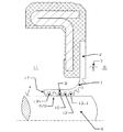
図1及び3には、それぞれ規定通りに密封すべき機械要素に装着され、使用状態にあるシールリングを示す。 1 and 3 each show a seal ring in use, mounted on a machine element to be sealed as specified.
図1及び3ではどちらの場合も、密封すべき機械要素5は回転軸である。
In both cases in FIGS. 1 and 3, the
図1及び3に示すシールリングはそれぞれ、ポリマー材料、特にここで示す実施例の場合にはポリテトラフルオロエチレン(PTFE)コンパウンドから成るシールスリーブ1を含む。回転軸5に装着されたこの状態において、回転軸5の軸を含む断面又は縦断面で見ると、シールスリーブ1はそれぞれ概略L字形となっており、かつ実質上半径方向に延伸する取付部2と、実質上軸方向に延伸する密封部3を含む。取付部2と密封部3は、ここで示された実施例の場合には、互いの材料が相互に移行し合いかつ同一のものから一体に形成されている。
Each of the seal rings shown in FIGS. 1 and 3 includes a
シールスリーブ1の密封部3は、密封すべき機械要素5の表面4を半径方向の予荷重をもって密封しながら取り囲んでいる。この回転軸5の表面4と半径方向で対向する密封部3の面には、密封すべき被密封媒体7を密封すべき被密封空間8に向かって送るために、逆流機構6として形成されている螺旋状の逆流溝12が設けられている。
The sealing
ここで示された2つの実施例の場合には、シールスリーブ1は、周囲の空間11に向かって軸方向に突出している。逆流機構6として形成されている輪郭9が、被密封空間8から周囲の空間11に向かって、送出容量10/送出量が減少するように形成されていることが重要である。この構成によって、比送出量は密封部に沿って全体にわたり同じとなる。即ち、逆流機構6の送出量は、被密封空間8に逆流させるべき被密封媒体7の量に一致している。
In the case of the two embodiments shown here, the sealing
ここで示す実施例の場合には、逆流溝12のピッチ14及び幅15、逆流溝の頂と頂、逆流溝の谷と谷の間隔は、密封部3に沿って実施上一定である。この実施例では、一定の比送出量を達成するための唯一の変量は溝の深さ13である。溝の深さ13は、密封部3に沿って次のように変化している。つまり逆流溝12は、被密封空間8から密封部3に沿って周囲の空間11に向かって、溝の深さ13が減少するように形成されている。密封部にある溝の最小の深さ13.nに対する、被密封空間8に対向する部分にある溝の最大の深さ13.1の比率は、ここで示す実施例の場合には4である。
In the case of the embodiment shown here, the
図1には、本考案によるシールリングの第1の実施例を示す。シールスリーブ1は、機械要素5の密封すべき表面4にのみ、逆流溝12の形状の輪郭9を有する。シールスリーブ1の機械要素5の表面4と反対側の表面は平坦な面として形成されている。
FIG. 1 shows a first embodiment of a seal ring according to the present invention. The sealing
逆流溝12の縦断面は、実質上台形となるように形成されている。
The longitudinal section of the
図2には、シールスリーブ1の密封部3を拡大して示す。
In FIG. 2, the sealing
図3は、本考案によるシールリングの第2の実施例を示すが、この実施例のシールリングは、図1に示すシールスリーブとは異なる形状のシールスリーブ1を有する。
FIG. 3 shows a second embodiment of the seal ring according to the present invention. The seal ring of this embodiment has a
図1のシールスリーブ1と異なり、図3のシールスリーブ1は、半径方向で回転軸5の表面4と反対側の密封部3の面に付加的に第2輪郭16を備えている。この第2輪郭16は、通常、第1輪郭9のものよりも、浅くかつ小さなピッチを有する溝から形成されている。
Unlike the
さらに、シールスリーブ1の自由端17は、周囲の空間11に対向して配置されている前置シール18を有し、この前置シールによって、周囲の空間11からの不純物が密封部3に侵入することを防ぐことができる。前置シール18とシールスリーブ1は、互いの材料が相互に移行し合いかつ同一のものから一体に形成されている。
Further, the
図5には、逆流溝12の幅及び/又はピッチ19/20が密封部3に沿って変化している第3の実施例を示す。この実施例では、取付部2から自由端17へ向かうにつれ、逆流溝12のピッチ14が狭く、かつ逆流溝12の深さ13が浅くなるように構成されている。
FIG. 5 shows a third embodiment in which the width and / or pitch 19/20 of the
図6には、本考案によるシールリングが組み込まれているハウジングシーリングキャップ21を示す。この図においては、ハウジングシーリングキャップ21において、静的に機能する固定シールには参照番号22を、測定装置/多極ホイールには参照番号23を、そして検出装置/センサーには参照番号24を付している。
FIG. 6 shows a
ここで示した実施例はいずれも、保護範囲を限定するものではなく、特に逆流機構6を、一条又は多条に、渦巻状、螺旋状又は同心状に形成することができ、かつ逆流溝は、縦断面で見て、例えば台形、三角形、鋸歯形又は無限軌道形に形成することができる。逆流溝12を、隔壁によって及び/又は環状の突出部によって遮断することができる。本明細書の実施例では、スリーブ1をPTFEコンパウンドから形成するものとして記載したが、シールスリーブ1には他の適切な材料を同様に使用することができる。
None of the embodiments shown here limit the protection range, and in particular, the reverse flow mechanism 6 can be formed in a single or multiple stripes, spirally, spirally or concentrically, and the reverse flow groove is For example, it can be formed in a trapezoidal shape, a triangular shape, a sawtooth shape, or an endless track shape when viewed in a longitudinal section. The
1 シールスリーブ
2 取付部
3 密封部
4 表面
5 回転軸
6 逆流機構
7 被密封媒体
8 被密封空間
9 第1輪郭
10 送出容量
11 周囲の空間
12 逆流溝
13 溝の深さ
14 ピッチ
15 溝間の幅
16 第2輪郭
17 自由端
18 前置シール
21 ハウジングシーリングキャップ
22 固定シール
23 多極ホイール
24 検出装置
DESCRIPTION OF
Claims (9)
前記密封部(3)が、前記表面(4)に対向する面に、被密封媒体(7)を被密封空間(8)に向かって送出する少なくとも1つの逆流機構(6)を有し、
前記逆流機構(6)が、前記被密封空間(8)から周囲の空間(11)に向かって、送出容量(10)が減少するように形成されている輪郭(9)を有し、
前記逆流機構(6)が、少なくとも1つの螺旋状の逆流溝(12)から形成され、
前記逆流溝(12)が、前記密封部(3)に沿って前記被密封空間(8)から前記周囲の空間(11)に向かって溝の深さ(13)が減少するように形成され
前記密封部(3)における溝の最小の深さ(13.n)に対する前記密封部(3)における溝の最大の深さ(13.1)の比率が2〜6の範囲にあるシールリング。 A substantially radially extending attachment and a substantially axially extending seal surrounding the surface of the machine element to be sealed with a radial preload, as specified. When used, a seal ring comprising a seal sleeve formed from a polymer material that is substantially L-shaped when viewed in longitudinal section,
The sealing part (3) has at least one backflow mechanism (6) for sending the sealed medium (7) toward the sealed space (8) on the surface facing the surface (4);
The backflow mechanism (6) has a contour (9) formed such that the delivery capacity (10) decreases from the sealed space (8) toward the surrounding space (11);
The backflow mechanism (6) is formed from at least one spiral backflow groove (12);
The reverse flow groove (12) is formed such that the groove depth (13) decreases from the sealed space (8) to the surrounding space (11) along the sealing portion (3). A seal ring in which the ratio of the maximum groove depth (13.1) in the sealing part (3) to the minimum groove depth (13.n) in the sealing part (3) is in the range of 2-6.
Applications Claiming Priority (1)
| Application Number | Priority Date | Filing Date | Title |
|---|---|---|---|
| DE10309907A DE10309907B4 (en) | 2003-03-07 | 2003-03-07 | seal |
Related Parent Applications (1)
| Application Number | Title | Priority Date | Filing Date |
|---|---|---|---|
| JP2004062272A Continuation JP2004270942A (en) | 2003-03-07 | 2004-03-05 | Seal ring |
Publications (1)
| Publication Number | Publication Date |
|---|---|
| JP3144908U true JP3144908U (en) | 2008-09-18 |
Family
ID=32797848
Family Applications (2)
| Application Number | Title | Priority Date | Filing Date |
|---|---|---|---|
| JP2004062272A Pending JP2004270942A (en) | 2003-03-07 | 2004-03-05 | Seal ring |
| JP2008004620U Expired - Lifetime JP3144908U (en) | 2003-03-07 | 2008-07-07 | Seal ring |
Family Applications Before (1)
| Application Number | Title | Priority Date | Filing Date |
|---|---|---|---|
| JP2004062272A Pending JP2004270942A (en) | 2003-03-07 | 2004-03-05 | Seal ring |
Country Status (7)
| Country | Link |
|---|---|
| US (1) | US20040173973A1 (en) |
| EP (1) | EP1455122B1 (en) |
| JP (2) | JP2004270942A (en) |
| AT (1) | ATE445114T1 (en) |
| CA (1) | CA2457185A1 (en) |
| DE (2) | DE10309907B4 (en) |
| MX (1) | MXPA04002029A (en) |
Families Citing this family (7)
| Publication number | Priority date | Publication date | Assignee | Title |
|---|---|---|---|---|
| JP2006266343A (en) * | 2005-03-23 | 2006-10-05 | Nok Corp | Sealing device |
| DE102005024006B4 (en) * | 2005-05-25 | 2015-09-03 | Ab Skf | compressor seal |
| US8925927B2 (en) * | 2006-02-10 | 2015-01-06 | Freudenberg-Nok General Partnership | Seal with controllable pump rate |
| US8376369B2 (en) | 2006-02-10 | 2013-02-19 | Freudenberg-Nok General Partnership | Seal with spiral grooves and contamination entrapment dams |
| US8505926B2 (en) * | 2010-03-11 | 2013-08-13 | Federal-Mogul Corporation | Low torque shaft seal with improved seal element bond joint |
| US8919782B2 (en) | 2012-10-19 | 2014-12-30 | Freudenberg-Nok General Partnership | Dynamic lay down lip seal with bidirectional pumping feature |
| US10711899B2 (en) | 2015-11-30 | 2020-07-14 | Nok Corporation | Seal device |
Family Cites Families (10)
| Publication number | Priority date | Publication date | Assignee | Title |
|---|---|---|---|---|
| AU1268870A (en) * | 1969-03-22 | 1971-09-23 | Super Oil Seals And Gaskets Limited | Improvements in or relating to seals |
| GB2167817B (en) * | 1984-12-03 | 1988-04-20 | Aeroquip | Rotary seal with variable pitch hydrothread |
| DE3545683C1 (en) * | 1985-12-21 | 1987-07-16 | Freudenberg Carl Fa | Shaft seal |
| DE59300790D1 (en) * | 1993-03-12 | 1995-11-23 | Bruss Dichtungstechnik | Method of making a shaft seal. |
| EP1024318A3 (en) * | 1999-01-29 | 2001-04-25 | Freudenberg-NOK General Partnership | Reverse seal |
| DE19922842A1 (en) * | 1999-05-19 | 2000-11-23 | Kaco Gmbh Co | Radial shaft seal comprises sealing ring with backflow device which has spiral groove extending between air side and medium side of device |
| DE10024026A1 (en) * | 2000-05-16 | 2001-11-29 | Freudenberg Carl Fa | Sealing sleeve, especially for installation spaces with small dimensions |
| DE10033446C5 (en) * | 2000-07-10 | 2006-12-14 | Dichtungstechnik G. Bruss Gmbh & Co. Kg | Shaft seal |
| US20030098545A1 (en) * | 2001-11-27 | 2003-05-29 | Webb Daniel S. | Gaming apparatus and method for play thereof |
| US6705617B2 (en) * | 2001-11-28 | 2004-03-16 | Federal-Mogul World Wide, Inc. | Hydrodynamic seal and method of making the same |
-
2003
- 2003-03-07 DE DE10309907A patent/DE10309907B4/en not_active Expired - Fee Related
-
2004
- 2004-02-10 CA CA002457185A patent/CA2457185A1/en not_active Abandoned
- 2004-03-03 EP EP04004953A patent/EP1455122B1/en not_active Expired - Lifetime
- 2004-03-03 MX MXPA04002029A patent/MXPA04002029A/en not_active Application Discontinuation
- 2004-03-03 DE DE502004010185T patent/DE502004010185D1/en not_active Expired - Lifetime
- 2004-03-03 AT AT04004953T patent/ATE445114T1/en not_active IP Right Cessation
- 2004-03-05 JP JP2004062272A patent/JP2004270942A/en active Pending
- 2004-03-05 US US10/794,713 patent/US20040173973A1/en not_active Abandoned
-
2008
- 2008-07-07 JP JP2008004620U patent/JP3144908U/en not_active Expired - Lifetime
Also Published As
| Publication number | Publication date |
|---|---|
| DE502004010185D1 (en) | 2009-11-19 |
| US20040173973A1 (en) | 2004-09-09 |
| MXPA04002029A (en) | 2004-09-09 |
| EP1455122B1 (en) | 2009-10-07 |
| JP2004270942A (en) | 2004-09-30 |
| CA2457185A1 (en) | 2004-09-07 |
| DE10309907B4 (en) | 2007-02-01 |
| DE10309907A1 (en) | 2004-09-16 |
| ATE445114T1 (en) | 2009-10-15 |
| EP1455122A1 (en) | 2004-09-08 |
Similar Documents
| Publication | Publication Date | Title |
|---|---|---|
| US6860486B2 (en) | Shaft sealing ring | |
| US5664787A (en) | Non-contacting shaft sealing device | |
| CA2087304C (en) | Radial seal | |
| US5873576A (en) | Skew and twist resistant hydrodynamic rotary shaft seal | |
| EP3156699B1 (en) | Seal device | |
| CN1322257C (en) | Labyrinth seal between rotatable components | |
| US20090127796A1 (en) | Sealing device | |
| US7891670B2 (en) | Multi-directional shaft seal | |
| KR910008320A (en) | Spiral home seal system for sealing high pressure gas | |
| JPWO2009130933A1 (en) | Sealing device | |
| CN112128381B (en) | A sealing device for gas-liquid two-phase fluid medium with variable working conditions | |
| JP2011122723A (en) | Seal device | |
| EP3321547B1 (en) | Seal assembly for a rotating member | |
| US11131387B2 (en) | Sealing ring and seal arrangement comprising such a sealing ring | |
| JP2004270942A (en) | Seal ring | |
| US20220282791A1 (en) | Seal ring | |
| EP1816377A1 (en) | Sealing device | |
| US11719343B2 (en) | Radial shaft seal | |
| JP7449136B2 (en) | Sealed rolling bearing | |
| JP3959577B2 (en) | Packing | |
| US6913264B2 (en) | Sealing arrangement | |
| JP2009008163A (en) | Sealing device | |
| JP2006057848A (en) | Seal ring with reflux groove | |
| CN108138965A (en) | Sealing device | |
| KR102565526B1 (en) | sliding member |
Legal Events
| Date | Code | Title | Description |
|---|---|---|---|
| R150 | Certificate of patent or registration of utility model |
Free format text: JAPANESE INTERMEDIATE CODE: R150 |
|
| FPAY | Renewal fee payment (event date is renewal date of database) |
Free format text: PAYMENT UNTIL: 20100827 Year of fee payment: 2 |
|
| EXPY | Cancellation because of completion of term | ||
| FPAY | Renewal fee payment (event date is renewal date of database) |
Free format text: PAYMENT UNTIL: 20100827 Year of fee payment: 2 |