JP3144923U - Direct liquid writing instrument - Google Patents

Direct liquid writing instrument Download PDF

Info

Publication number
JP3144923U
JP3144923U JP2008004648U JP2008004648U JP3144923U JP 3144923 U JP3144923 U JP 3144923U JP 2008004648 U JP2008004648 U JP 2008004648U JP 2008004648 U JP2008004648 U JP 2008004648U JP 3144923 U JP3144923 U JP 3144923U
Authority
JP
Japan
Prior art keywords
ink cartridge
wall
ink
end opening
connecting pipe
Prior art date
Legal status (The legal status is an assumption and is not a legal conclusion. Google has not performed a legal analysis and makes no representation as to the accuracy of the status listed.)
Expired - Lifetime
Application number
JP2008004648U
Other languages
Japanese (ja)
Inventor
久嗣 岩田
Current Assignee (The listed assignees may be inaccurate. Google has not performed a legal analysis and makes no representation or warranty as to the accuracy of the list.)
Pilot Ink Co Ltd
Original Assignee
Pilot Ink Co Ltd
Priority date (The priority date is an assumption and is not a legal conclusion. Google has not performed a legal analysis and makes no representation as to the accuracy of the date listed.)
Filing date
Publication date
Application filed by Pilot Ink Co Ltd filed Critical Pilot Ink Co Ltd
Priority to JP2008004648U priority Critical patent/JP3144923U/en
Application granted granted Critical
Publication of JP3144923U publication Critical patent/JP3144923U/en
Anticipated expiration legal-status Critical
Expired - Lifetime legal-status Critical Current

Links

Images

Landscapes

  • Pens And Brushes (AREA)

Abstract

【課題】落下等の衝撃が加わった場合でも、インキカートリッジが接続管部から外れてインキカートリッジ内のインキが外部に漏出するおそれがない直液式筆記具を提供する。
【解決手段】前端にペン先2を備えたインキ保留部材6を軸筒3の前端開口部に設ける。インキ保留部材6の後方の軸筒3内に接続管部42を設ける。接続管部42を、インキを直に貯溜するインキカートリッジ8の前端開口部に挿入する。接続管部42の外壁とインキカートリッジ8の前端開口部の内壁とを密接嵌合させてインキ保留部材6とインキカートリッジ8内部とを連通させる。インキ保留部材6とインキカートリッジ8内部との連通状態で、インキカートリッジ8が軸筒3内に収容される。接続管部42の外壁とインキカートリッジ8の前端開口部の内壁とが環状に密接嵌合しながら軸方向に移動可能である。
【選択図】図1
Provided is a direct liquid writing instrument in which an ink cartridge is not detached from a connecting pipe portion and ink in the ink cartridge does not leak to the outside even when an impact such as dropping is applied.
An ink retaining member having a nib at a front end is provided at a front end opening of a shaft tube. A connecting pipe portion 42 is provided in the shaft cylinder 3 behind the ink storage member 6. The connecting tube portion 42 is inserted into the front end opening of the ink cartridge 8 that directly stores ink. The ink retaining member 6 and the inside of the ink cartridge 8 are communicated with each other by closely fitting the outer wall of the connecting pipe portion 42 and the inner wall of the front end opening of the ink cartridge 8. The ink cartridge 8 is accommodated in the shaft cylinder 3 in a communication state between the ink holding member 6 and the ink cartridge 8. The outer wall of the connecting tube portion 42 and the inner wall of the front end opening of the ink cartridge 8 are movable in the axial direction while closely fitting in an annular shape.
[Selection] Figure 1

Description

本考案は、直液式筆記具に関する。詳細には、インキカートリッジ内部にインキが直に貯留された直液式筆記具に関する。 The present invention relates to a direct liquid writing instrument. Specifically, the present invention relates to a direct liquid writing instrument in which ink is stored directly in an ink cartridge.

従来この種の直液式筆記具において、例えば、特許文献1には、インキ保留体(本考案のインキ保留部材に相当)の後方に突刺管(本考案の接続管部に相当)が突設され、前記突刺管にインキ筒(本考案のインキカートリッジに相当)が接続される構造が開示されている。 Conventionally, in this type of direct liquid writing instrument, for example, in Patent Document 1, a piercing tube (corresponding to the connecting tube portion of the present invention) is provided behind the ink retaining member (corresponding to the ink retaining member of the present invention). A structure in which an ink cylinder (corresponding to the ink cartridge of the present invention) is connected to the piercing tube is disclosed.

前記従来の構造において、インキ筒が接続された状態で落下等の衝撃が加わった場合、インキ筒が後方に移動し、インキ筒が突刺管から外れ、インキ筒内のインキが外部に漏出するおそれがある。 In the conventional structure, when an impact such as dropping is applied with the ink cylinder connected, the ink cylinder may move backward, the ink cylinder may come off from the piercing tube, and the ink in the ink cylinder may leak to the outside There is.

実開昭61−177881号明細書Japanese Utility Model Publication No. 61-177881

本考案は前記従来の問題点を解決するものであって、落下等の衝撃が加わった場合でも、インキカートリッジが接続管部から外れてインキカートリッジ内のインキが外部に漏出するおそれがない直液式筆記具を提供しようとするものである。尚、本考案において、「前」とはペン先側を指し、「後」とはインキカートリッジ側を指す。 The present invention solves the above-mentioned conventional problems, and even when an impact such as dropping is applied, there is no possibility that the ink cartridge is detached from the connecting pipe portion and the ink in the ink cartridge leaks to the outside. It is intended to provide a formula writing instrument. In the present invention, “front” refers to the pen tip side, and “rear” refers to the ink cartridge side.

[1]本考案は、前端にペン先2を備えたインキ保留部材6を軸筒3の前端開口部に設け、前記インキ保留部材6の後方の軸筒3内に接続管部42を設け、前記接続管部42を、インキを直に貯溜するインキカートリッジ8の前端開口部に挿入し、前記接続管部42の外壁と前記インキカートリッジ8の前端開口部の内壁とを密接嵌合させてインキ保留部材6とインキカートリッジ8内部とを連通し、前記インキ保留部材6とインキカートリッジ8内部との連通状態で、前記インキカートリッジ8が軸筒3内に収容されてなる直液式筆記具であって、前記接続管部42の外壁と前記インキカートリッジ8の前端開口部の内壁とが環状に密接嵌合しながら軸方向に移動可能であること(請求項1)を要件とする。 [1] In the present invention, an ink retaining member 6 having a nib 2 at the front end is provided in the front end opening of the shaft cylinder 3, and a connecting tube portion 42 is provided in the shaft cylinder 3 behind the ink retaining member 6. The connecting tube portion 42 is inserted into the front end opening of the ink cartridge 8 that directly stores ink, and the outer wall of the connecting tube portion 42 and the inner wall of the front end opening of the ink cartridge 8 are closely fitted to each other. A direct liquid writing instrument in which the retaining member 6 communicates with the inside of the ink cartridge 8, and the ink cartridge 8 is accommodated in the shaft cylinder 3 in a communicating state between the ink retaining member 6 and the ink cartridge 8. The outer wall of the connecting pipe portion 42 and the inner wall of the front end opening of the ink cartridge 8 are capable of moving in the axial direction while closely fitting in an annular shape (Claim 1).

前記直液式筆記具1(請求項1)において、落下等の衝撃が加わりインキカートリッジ8が後方に移動したとしても、接続管部42の外壁とインキカートリッジ8の前端開口部の内壁との密接嵌合状態が維持され、インキカートリッジ8内のインキが外部に漏出するおそれがない。 In the direct liquid writing instrument 1 (Claim 1), even if an impact such as dropping is applied and the ink cartridge 8 moves rearward, the outer wall of the connecting pipe portion 42 and the inner wall of the front end opening of the ink cartridge 8 are closely fitted. The combined state is maintained, and there is no possibility that the ink in the ink cartridge 8 leaks to the outside.

[2]前記直液式筆記具1において、前記接続管部42の外壁と前記インキカートリッジ8の前端開口部の内壁とが密接嵌合を開始してから密接嵌合が終了するまでのカートリッジの軸方向前方への移動可能量をAとし、軸筒3内において密接嵌合終了状態からインキカートリッジ8が後方に移動した際にインキカートリッジ8外壁が軸筒3内壁に当接するまでの軸方向後方への移動可能量をBとするとき、A>Bの関係を満足すること(請求項2)が好ましい。 [2] In the direct liquid writing instrument 1, the shaft of the cartridge from when the outer wall of the connecting pipe part 42 and the inner wall of the front end opening of the ink cartridge 8 start to closely fit until the close fitting ends. A forward movement of the ink cartridge 8 is defined as A, and when the ink cartridge 8 moves rearward from the close fitting state in the shaft cylinder 3, the ink cartridge 8 outer wall contacts the inner wall of the shaft cylinder 3 rearward in the axial direction. It is preferable that the relationship of A> B is satisfied, where B is the movable amount of (Claim 2).

前記直液式筆記具1(請求項2)において、落下等の衝撃が加わり軸筒3内のインキカートリッジ8が後方に移動したとしても、前記関係「A>B」を満足することにより、インキカートリッジ8が後方に移動する際、接続管部42の外壁とインキカートリッジ8の前端開口部の内壁との密接嵌合状態が維持されるとともに、インキカートリッジ8外壁が軸筒3内壁に当接し、インキカートリッジ8の後方移動が規制される。それにより、インキカートリッジ8内のインキが外部に漏出することを確実に防止できる。 In the direct liquid writing instrument 1 (Claim 2), even when an impact such as dropping is applied and the ink cartridge 8 in the shaft cylinder 3 moves backward, the ink cartridge is satisfied by satisfying the relation "A> B". When the 8 moves backward, the outer wall of the connecting pipe portion 42 and the inner wall of the front end opening of the ink cartridge 8 are maintained in close contact with each other, and the outer wall of the ink cartridge 8 abuts against the inner wall of the shaft cylinder 3. The rearward movement of the cartridge 8 is restricted. This reliably prevents the ink in the ink cartridge 8 from leaking outside.

[3]前記直液式筆記具1において、インキカートリッジ8が後方に移動した際に、インキカートリッジ8の後端部の外壁が軸筒3の後端部の内壁に当接されること(請求項3)が好ましい。 [3] In the direct liquid writing instrument 1, when the ink cartridge 8 moves rearward, the outer wall of the rear end portion of the ink cartridge 8 is brought into contact with the inner wall of the rear end portion of the shaft cylinder 3. 3) is preferred.

前記直液式筆記具1(請求項3)により、軸筒3の内部の限られた収容空間に、できる限り大きなインキカートリッジ8を収容することができる。なぜなら、もし、インキカートリッジ8の後方移動を規制する部分を、軸筒3の中間部やインキカートリッジ8の中間部に設けた場合、軸筒3の後端部内壁とインキカートリッジ8の後端部外壁との間に大きな隙間が形成されるおそれがあり、それにより、インキカートリッジ8が小さく設定され(インキカートリッジ8の容量が少なく設定され)、特に、軸筒3を透明にすると、ユーザーに小さいインキカートリッジ8を視認させ、上げ底のような印象を与えることになるからである。 With the direct liquid writing instrument 1 (Claim 3), the largest possible ink cartridge 8 can be accommodated in the limited accommodating space inside the shaft cylinder 3. This is because if the portion for restricting the rearward movement of the ink cartridge 8 is provided in the intermediate portion of the shaft tube 3 or the intermediate portion of the ink cartridge 8, the inner wall of the rear end portion of the shaft tube 3 and the rear end portion of the ink cartridge 8 There is a possibility that a large gap may be formed between the outer wall and the ink cartridge 8 is set to be small (the capacity of the ink cartridge 8 is set to be small). This is because the ink cartridge 8 is visually recognized and an impression like a raised bottom is given.

[4]前記直液式筆記具1において、前記接続管部42の外壁に環状突起42aを形成し、前記インキカートリッジ8の前端開口部の内壁に環状平滑面8aを形成し、前記環状突起42aと前記環状平滑面8aとが環状に密接嵌合してなること(請求項4)が好ましい。 [4] In the direct liquid writing instrument 1, an annular protrusion 42a is formed on the outer wall of the connecting pipe portion 42, an annular smooth surface 8a is formed on the inner wall of the front end opening of the ink cartridge 8, and the annular protrusion 42a It is preferable that the annular smooth surface 8a is closely fitted in an annular shape (Claim 4).

前記直液式筆記具1(請求項4)により、一方を環状突起42aにし、他方を環状平滑面8aにしたことにより、接続管部42とインキカートリッジ8との密接嵌合部の両者を、環状平滑面にする構成または環状の凹凸にする構成でないため、軸方向の密接摺動(即ち環状に密接嵌合しながら軸方向に移動すること)を、より確実に行うことができる。 With the direct liquid writing instrument 1 (Claim 4), one is an annular protrusion 42a and the other is an annular smooth surface 8a, so that both of the close fitting portions of the connecting pipe portion 42 and the ink cartridge 8 are annular. Since it is not the structure which makes it a smooth surface, or the structure which makes an annular unevenness | corrugation, it can carry out more reliably the axial close sliding (namely, moving to an axial direction, closely fitting annularly).

[5]前記直液式筆記具1において、前記接続管部42の外壁に環状平滑面42bを形成し、前記インキカートリッジ8の前端開口部の内壁に環状突起8bを形成し、前記環状平滑面42bと前記環状突起8bとが環状に密接嵌合してなること(請求項5)が好ましい。 [5] In the direct liquid writing instrument 1, an annular smooth surface 42b is formed on the outer wall of the connecting pipe portion 42, an annular protrusion 8b is formed on the inner wall of the front end opening of the ink cartridge 8, and the annular smooth surface 42b. It is preferable that the annular protrusion 8b is closely fitted in an annular shape (Claim 5).

前記直液式筆記具1(請求項5)により、一方を環状突起8bにし、他方を環状平滑面42bにしたことにより、接続管部42とインキカートリッジ8との密接嵌合部の両者を、環状平滑面にする構成または環状の凹凸にする構成でないため、軸方向の密接摺動(即ち環状に密接嵌合しながら軸方向に移動すること)を、より確実に行うことができる。 With the direct liquid writing instrument 1 (Claim 5), one is an annular protrusion 8b and the other is an annular smooth surface 42b, so that both of the close fitting portions of the connecting pipe portion 42 and the ink cartridge 8 are annular. Since it is not the structure which makes it a smooth surface, or the structure which makes an annular unevenness | corrugation, it can carry out more reliably the axial close sliding (namely, moving to an axial direction, closely fitting annularly).

請求項1の直液式筆記具によれば、落下等の衝撃が加わったとしても、接続管部の外壁とインキカートリッジの前端開口部の内壁との密接嵌合状態が維持されるため、インキカートリッジ内のインキが外部に漏出するおそれがない。 According to the direct liquid type writing instrument of claim 1, even when an impact such as dropping is applied, the close fitting state between the outer wall of the connecting pipe portion and the inner wall of the front end opening of the ink cartridge is maintained. There is no risk of the ink inside leaking out.

請求項2の直液式筆記具によれば、落下等の衝撃が加わったとしても、接続管部の外壁とインキカートリッジの前端開口部の内壁との密接嵌合状態が維持されるとともに、インキカートリッジの後方移動が規制されるため、インキカートリッジ内のインキが外部に漏出することを確実に防止できる。 According to the direct liquid type writing instrument of claim 2, even if an impact such as dropping is applied, the outer wall of the connecting pipe portion and the inner wall of the front end opening of the ink cartridge are maintained in close contact, and the ink cartridge Therefore, it is possible to reliably prevent the ink in the ink cartridge from leaking outside.

請求項3の直液式筆記具によれば、軸筒の内部の限られた収容空間に、できる限り大きなインキカートリッジを収容することができる。 According to the third aspect of the present invention, the ink cartridge as large as possible can be accommodated in the limited accommodation space inside the shaft cylinder.

請求項4の直液式筆記具によれば、軸方向の密接摺動を、より確実に行うことができる。 According to the direct liquid writing instrument of the fourth aspect, the close sliding in the axial direction can be more reliably performed.

請求項5の直液式筆記具によれば、軸方向の密接摺動を、より確実に行うことができる。 According to the direct liquid type writing instrument of the fifth aspect, the close sliding in the axial direction can be more reliably performed.

[第1の実施の形態]
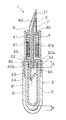
図1に本考案の直液式筆記具1の第1の実施の形態を示す。本実施の形態の直液式筆記具1は、主に、前軸4と後軸5とからなる軸筒3と、前記前軸4内に収容され、前端にペン先2を備えたインキ保留部材6と、前記後軸5内に収容されるインキカートリッジ8とからなる。
[First Embodiment]
FIG. 1 shows a first embodiment of a direct liquid writing instrument 1 according to the present invention. The direct liquid writing instrument 1 according to the present embodiment mainly includes a shaft cylinder 3 including a front shaft 4 and a rear shaft 5, and an ink holding member that is accommodated in the front shaft 4 and includes a pen tip 2 at a front end. 6 and an ink cartridge 8 accommodated in the rear shaft 5.

・前軸
前記前軸4は、円筒状の前側筒部41と、該前側筒部41の底壁から後方に一体に連設され且つ前側筒部41より小径円筒状の接続管部42と、前記前側筒部41の底壁より後方に一体に連設され且つ前記接続管部42の外周を同心状に包囲するよう配置された円筒状の後側筒部43と、前記接続管部42の後端部に一体に形成されたインキカートリッジ開栓用の突片44とからなる。前記前軸4は、透明な合成樹脂(例えば、ポリプロピレン)の射出成形により得られる。また、前記後側筒部43の外壁には、雄ネジ部が形成される。
Front shaft The front shaft 4 includes a cylindrical front tube portion 41, a connecting pipe portion 42 that is integrally connected to the rear from the bottom wall of the front tube portion 41 and has a smaller diameter than the front tube portion 41, and A cylindrical rear cylinder portion 43 that is integrally connected to the rear side of the bottom wall of the front cylinder portion 41 and that concentrically surrounds the outer periphery of the connection tube portion 42; And a protrusion 44 for opening the ink cartridge integrally formed at the rear end. The front shaft 4 is obtained by injection molding of a transparent synthetic resin (for example, polypropylene). A male thread portion is formed on the outer wall of the rear cylinder portion 43.

・接続管部
前記接続管部42の外壁には、インキカートリッジ8の前端開口部の内壁と円周面状に密接可能な密接嵌合部が形成される。前記密接嵌合部は、軸方向の適宜寸法を備えるとともに、インキカートリッジ8の前端開口部の内径より僅かに大きい外径を有する。さらに、前記密接嵌合部の後端部には、環状突起42aが一体に形成される。前記環状突起42aは、少なくとも一つ形成されればよく、本実施の形態では一つのみであるが、これ以外にも複数(例えば二つ)形成されてもよい。
-Connection pipe part The outer wall of the connection pipe part 42 is formed with a close fitting part that can be in close contact with the inner wall of the front end opening of the ink cartridge 8 in a circumferential surface shape. The close fitting portion has an appropriate dimension in the axial direction and has an outer diameter slightly larger than the inner diameter of the front end opening of the ink cartridge 8. Further, an annular protrusion 42a is integrally formed at the rear end portion of the close fitting portion. At least one annular protrusion 42a may be formed. In the present embodiment, only one annular protrusion 42a is formed, but a plurality (for example, two) may be formed in addition to this.

・後軸
前記後軸5は、前端が開口され且つ後端が閉鎖された有底筒体であり、透明な合成樹脂(例えば、ポリカーボネイト)の射出成形により得られる。前記後軸5の前端開口部の内壁には、雌ネジ部が形成される。前記雌ネジ部は、前記前軸4の前側筒部41の外壁の雄ネジ部と螺合可能であり、それにより、前記後軸5の前端部は前軸4の後端部と着脱自在に螺着される。
-Rear shaft The rear shaft 5 is a bottomed cylindrical body having a front end opened and a rear end closed, and is obtained by injection molding of a transparent synthetic resin (for example, polycarbonate). A female screw portion is formed on the inner wall of the front end opening of the rear shaft 5. The female threaded portion can be screwed with a male threaded portion on the outer wall of the front cylindrical portion 41 of the front shaft 4, whereby the front end portion of the rear shaft 5 is detachable from the rear end portion of the front shaft 4. Screwed.

・インキ保留部材
前記インキ保留部材6は、インキカートリッジ8内の圧力上昇に応じた余剰インキを一時的に保持する部材である。前記インキ保留部材6は、複数の櫛歯よりなるインキ保留部61(櫛溝部)と、該インキ保留部61の後端(即ち後端櫛歯66後端面)より後方に突出され且つ該インキ保留部61の外径より小さい外径を有する縮径筒部62と、前記インキ保留部61の前端より前方に突出されたペン先取付部63とが、一体に形成された合成樹脂(例えば、ABS樹脂)の射出成形体よりなる。また、前記インキ保留部材6の軸心には、軸方向に延び且つ後端が後方に開口された軸心孔64が設けられる。前記軸心孔64にはインキ誘導芯7が挿着される。前記ペン先取付部63には、ペン先2が取り付けられる。尚、本考案におけるインキ保留部材6は、前記構成以外にも、インキ保留部61が螺旋状溝や迷路状溝からなるもの、あるいは、インキ保留部61が繊維材料または多孔質材料からなるもの等、いずれであってもよい。
Ink retaining member The ink retaining member 6 is a member that temporarily retains excess ink corresponding to a pressure increase in the ink cartridge 8. The ink retaining member 6 protrudes rearward from the ink retaining portion 61 (comb groove portion) composed of a plurality of comb teeth and the rear end of the ink retaining portion 61 (that is, the rear end surface of the rear end comb teeth 66) and the ink retaining portion. A synthetic resin (for example, ABS) in which a reduced diameter cylindrical portion 62 having an outer diameter smaller than the outer diameter of the portion 61 and a pen tip mounting portion 63 protruding forward from the front end of the ink retaining portion 61 are integrally formed. Resin). Further, an axial hole 64 extending in the axial direction and having a rear end opened rearward is provided in the axial center of the ink retaining member 6. The ink guide core 7 is inserted into the axial hole 64. The pen tip 2 is attached to the pen tip attaching portion 63. In addition to the above-described configuration, the ink retaining member 6 in the present invention has an ink retaining portion 61 formed of a spiral groove or a labyrinth groove, or an ink retaining portion 61 formed of a fiber material or a porous material. Any of these may be used.

前記インキ保留部材6は前軸4内に挿着される。即ち、前記インキ保留部材6のインキ保留部61は、前軸4の前側筒部41内に挿入配置され、前記インキ保留部材6の縮径筒部62は、前軸4の接続管部42内に挿入配置される。このとき、ペン先2及びペン先取付部63が前軸4の前端より前方に突出される。また、前記前軸4の前端(即ちインキ保留部61の前端)には空気孔65が開口される。前記空気孔65によりインキ保留部61と外気とが連通される。 The ink retaining member 6 is inserted into the front shaft 4. That is, the ink retaining portion 61 of the ink retaining member 6 is inserted and disposed in the front cylinder portion 41 of the front shaft 4, and the reduced diameter cylindrical portion 62 of the ink retaining member 6 is disposed in the connecting tube portion 42 of the front shaft 4. Is inserted and arranged. At this time, the pen tip 2 and the pen tip attachment portion 63 protrude forward from the front end of the front shaft 4. An air hole 65 is opened at the front end of the front shaft 4 (that is, the front end of the ink retaining portion 61). The ink retaining portion 61 and the outside air communicate with each other through the air holes 65.

前記インキ保留部61には、軸方向に延び且つ径方向外方に開口する第1のスリットが61a形成される。前記第1のスリット61aにより、インキ保留部61の櫛歯間が連通される。前記縮径筒部62の外壁には、軸方向に延び且つ径方向外方に開口する第2のスリット62aが形成される。前記第2のスリット62aは、前端が第1のスリット61aと接続され、後端が軸方向後方(即ちインキカートリッジ8内)に開口される。前記第1のスリット61a及び第2のスリット62aと軸心孔64とは径方向に非連通に構成される。また、前記第1のスリット61aと前記第2のスリット62aとが、同一軸線上に形成されている。 The ink retaining part 61 is formed with a first slit 61a extending in the axial direction and opening radially outward. The first slit 61a allows communication between the comb teeth of the ink retaining portion 61. On the outer wall of the reduced diameter cylindrical portion 62, a second slit 62a is formed that extends in the axial direction and opens radially outward. The front end of the second slit 62a is connected to the first slit 61a, and the rear end is opened rearward in the axial direction (that is, in the ink cartridge 8). The first slit 61a, the second slit 62a, and the axial hole 64 are configured so as not to communicate with each other in the radial direction. Further, the first slit 61a and the second slit 62a are formed on the same axis.

前記軸心孔64には、インキ誘導芯7が挿着される。前記インキ誘導芯7は、毛細管力を有する軸方向のインキ導出路を備えるものであればいずれであってもよく、本実施例では、繊維の樹脂加工により得られる棒状体が採用されているが、これ以外にも、例えば、多孔質体、合成樹脂の押出成形体が挙げられる。前記インキ誘導芯7の前端は、ペン先2に接続され、前記インキ誘導芯7の後端は、縮径筒部62の後端面と略一致している。 The ink guide core 7 is inserted into the axial hole 64. The ink guide core 7 may be any one provided with an axial ink lead-out path having a capillary force. In this embodiment, a rod-like body obtained by fiber resin processing is employed. Besides these, for example, a porous body and an extruded body of a synthetic resin can be mentioned. The front end of the ink guide core 7 is connected to the pen tip 2, and the rear end of the ink guide core 7 substantially coincides with the rear end surface of the reduced diameter cylindrical portion 62.

前記ペン先2は、ペン先取付部63に取り付けられる。本実施の形態では、前記ペン先2は、前端に切り割り21を有する金属板製ペン体(いわゆる万年筆ペン体)が採用されている。前記ペン先2前端の切り割り21には、インキ誘導芯7の前端が圧接状態で接続されている。尚、本考案において、ペン先2は、前記金属板製ペン体の他、例えば、ボールペンチップ、繊維ペン体、多孔質ペン体、合成樹脂の押出成形体よりなるプラスチックペン体、パイプ状ペン体、毛筆ペン体等が挙げられる。また、前記ペン先2は、インキ誘導芯7を兼ねるものでもよい。 The nib 2 is attached to the nib attaching part 63. In the present embodiment, the pen nib 2 employs a metal plate pen body (so-called fountain pen pen body) having a slit 21 at the front end. The front end of the ink guide core 7 is connected to the slit 21 at the front end of the nib 2 in a pressure contact state. In the present invention, the nib 2 is, for example, a ballpoint pen tip, a fiber pen body, a porous pen body, a plastic pen body made of a synthetic resin extruded body, and a pipe-shaped pen body in addition to the metal plate pen body. And a brush pen body. The nib 2 may also serve as the ink guide core 7.

・インキカートリッジ
前記インキカートリッジ8は、前端が開口され且つ後端が閉鎖された有底筒体よりなり、合成樹脂(例えばポリエチレン)の射出成形により得られる。前記インキカートリッジ8の前端開口部の内壁には、環状平滑面8aに形成される。前記インキカートリッジ8内にはインキが直に貯溜される。前記インキカートリッジ8の前端開口部には栓体81が固着され、それにより、インキカートリッジ8内は密封状態となる。前記密封状態のインキカートリッジ8の前端開口部に前記接続管部42を挿入すると、接続管部42の後端に形成された突片44により栓体81が後方に押圧され、栓体81がインキカートリッジ8内に外され、インキカートリッジ8が開栓される。このとき、接続管部42の外壁の密接嵌合部(環状突起42a)とインキカートリッジ8の前端開口部の内壁とは密嵌状態(密接嵌合状態)にある。
Ink cartridge The ink cartridge 8 is a bottomed cylindrical body having a front end opened and a rear end closed, and is obtained by injection molding of a synthetic resin (for example, polyethylene). On the inner wall of the front end opening of the ink cartridge 8, an annular smooth surface 8a is formed. Ink is stored directly in the ink cartridge 8. A plug 81 is fixed to the opening of the front end of the ink cartridge 8, whereby the ink cartridge 8 is hermetically sealed. When the connecting pipe portion 42 is inserted into the front end opening of the sealed ink cartridge 8, the plug body 81 is pushed backward by the projecting piece 44 formed at the rear end of the connecting pipe section 42, and the plug body 81 is inked. The ink cartridge 8 is unplugged and the ink cartridge 8 is opened. At this time, the close fitting part (annular protrusion 42a) of the outer wall of the connecting pipe part 42 and the inner wall of the front end opening of the ink cartridge 8 are in a close fitting state (close fitting state).

前記接続管部42の外壁の環状突起42aと、前記インキカートリッジ8の前端開口部の内壁の環状平滑面8aとは、環状に密接嵌合しながら軸方向に移動可能である。前記インキカートリッジ8が軸筒内において後方に移動した際、インキカートリッジ8の後端部の外壁は、軸筒3の後端部(即ち後軸5の後端部)の内壁に当接され、その後方移動が規制される。 An annular protrusion 42a on the outer wall of the connecting pipe portion 42 and an annular smooth surface 8a on the inner wall of the front end opening of the ink cartridge 8 are movable in the axial direction while closely fitting in an annular shape. When the ink cartridge 8 moves rearward in the shaft cylinder, the outer wall of the rear end portion of the ink cartridge 8 is brought into contact with the inner wall of the rear end portion of the shaft cylinder 3 (that is, the rear end portion of the rear shaft 5). Later movement is restricted.

軸筒3内において密接嵌合終了状態からインキカートリッジ8が後方に移動した際にインキカートリッジ8外壁が軸筒3内壁(即ち後軸5の内壁)に当接するまでの軸方向後方への移動可能量Bは、接続管部42の外壁の環状突起42aとインキカートリッジ8の前端開口部の内壁の環状平滑面8aとが密接嵌合を開始してからその密接嵌合が終了するまでのカートリッジの軸方向前方への移動可能量Aよりも小さく設定されている(即ちA>B)。 When the ink cartridge 8 moves rearward from the close fitting state in the shaft cylinder 3, the ink cartridge 8 can move rearward in the axial direction until the outer wall of the ink cartridge 8 contacts the inner wall of the shaft cylinder 3 (that is, the inner wall of the rear shaft 5). The amount B of the cartridge from the start of close fitting of the annular protrusion 42a on the outer wall of the connecting pipe portion 42 and the annular smooth surface 8a of the inner wall of the front end opening of the ink cartridge 8 to the end of the close fitting. It is set to be smaller than the axially movable amount A (that is, A> B).

・落下衝撃時
本実施の形態において、インキカートリッジ8が後軸5内に収容された状態の直液式筆記具1に、落下等の衝撃が加わった際、インキカートリッジ8が軸筒3内で後方に移動したとしても、インキカートリッジ8の後端部の外壁が軸筒3の後端部(即ち後軸5の後端部)の内壁に当接し、インキカートリッジ8の後方移動が規制される。前記インキカートリッジ8の後方移動が規制されるまで、接続管部42の外壁の環状突起42aとインキカートリッジ8の前端開口部の内壁の環状平滑面8aとの密接嵌合状態が維持される。その結果、インキカートリッジ8が接続管部42から外れることがない。
In the case of a drop impact In this embodiment, when an impact such as a drop is applied to the direct liquid writing instrument 1 in a state where the ink cartridge 8 is accommodated in the rear shaft 5, the ink cartridge 8 moves backward in the shaft cylinder 3. The rear wall of the ink cartridge 8 is in contact with the inner wall of the rear end portion of the shaft cylinder 3 (that is, the rear end portion of the rear shaft 5), and the rearward movement of the ink cartridge 8 is restricted. Until the rearward movement of the ink cartridge 8 is restricted, the close fitting state between the annular protrusion 42a on the outer wall of the connecting pipe portion 42 and the annular smooth surface 8a on the inner wall of the front end opening of the ink cartridge 8 is maintained. As a result, the ink cartridge 8 does not come off from the connecting pipe portion 42.

[第2の実施の形態]
図2に本考案の直液式筆記具1の第2の実施の形態を示す。本実施の形態の直液式筆記具1は、主に、前軸4と後軸5とからなる軸筒3と、前記前軸4内に収容され、前端にペン先2を備えたインキ保留部材6と、前記後軸5内に収容されるインキカートリッジ8とからなる。
[Second Embodiment]
FIG. 2 shows a second embodiment of the direct liquid writing instrument 1 of the present invention. The direct liquid writing instrument 1 according to the present embodiment mainly includes a shaft cylinder 3 including a front shaft 4 and a rear shaft 5, and an ink holding member that is accommodated in the front shaft 4 and includes a pen tip 2 at a front end. 6 and an ink cartridge 8 accommodated in the rear shaft 5.

・前軸
前記前軸4は、円筒状の前側筒部41と、該前側筒部41の底壁から後方に一体に連設され且つ前側筒部41より小径円筒状の接続管部42と、前記前側筒部41の底壁より後方に一体に連設され且つ前記接続管部42の外周を同心状に包囲するよう配置された円筒状の後側筒部43と、前記接続管部42の後端部に一体に形成されたインキカートリッジ開栓用の突片44とからなる。前記前軸4は、合成樹脂(例えば、ポリプロピレン)の射出成形により得られる。また、前記後側筒部43の外壁には、雄ネジ部が形成される。
Front shaft The front shaft 4 includes a cylindrical front tube portion 41, a connecting pipe portion 42 that is integrally connected to the rear from the bottom wall of the front tube portion 41 and has a smaller diameter than the front tube portion 41, and A cylindrical rear cylinder portion 43 that is integrally connected to the rear side of the bottom wall of the front cylinder portion 41 and that concentrically surrounds the outer periphery of the connection tube portion 42; And a protrusion 44 for opening the ink cartridge integrally formed at the rear end. The front shaft 4 is obtained by injection molding of a synthetic resin (for example, polypropylene). A male thread portion is formed on the outer wall of the rear cylinder portion 43.

・接続管部
前記接続管部42の外壁には、インキカートリッジ8の前端開口部の内壁と円周面状に密接可能な密接嵌合部が形成される。前記密接嵌合部は、軸方向の適宜寸法を備えるとともに、インキカートリッジ8の前端開口部の内径より僅かに大きい外径を有する。前記密接嵌合部は、環状平滑面42bにより構成される。
-Connection pipe part The outer wall of the connection pipe part 42 is formed with a close fitting part that can be in close contact with the inner wall of the front end opening of the ink cartridge 8 in a circumferential surface shape. The close fitting portion has an appropriate dimension in the axial direction and has an outer diameter slightly larger than the inner diameter of the front end opening of the ink cartridge 8. The close fitting portion is constituted by an annular smooth surface 42b.

・後軸
前記後軸5は、前端が開口され且つ後端が閉鎖された有底筒体であり、合成樹脂(例えば、ポリカーボネイト)の射出成形により得られる。前記後軸5の前端開口部の内壁には、雌ネジ部が形成される。前記雌ネジ部は、前記前軸4の前側筒部41の外壁の雄ネジ部と螺合可能であり、それにより、前記後軸5の前端部は前軸4の後端部と着脱自在に螺着される。
Rear shaft The rear shaft 5 is a bottomed cylindrical body having a front end opened and a rear end closed, and is obtained by injection molding of a synthetic resin (for example, polycarbonate). A female screw portion is formed on the inner wall of the front end opening of the rear shaft 5. The female threaded portion can be screwed with a male threaded portion on the outer wall of the front cylindrical portion 41 of the front shaft 4, whereby the front end portion of the rear shaft 5 is detachable from the rear end portion of the front shaft 4. Screwed.

・インキ保留部材
前記インキ保留部材6は、インキカートリッジ8内の圧力上昇に応じた余剰インキを一時的に保持する部材である。前記インキ保留部材6は、複数の櫛歯よりなるインキ保留部61(櫛溝部)と、該インキ保留部61の後端(即ち後端櫛歯66後端面)より後方に突出され且つ該インキ保留部61の外径より小さい外径を有する縮径筒部62と、前記インキ保留部61の前端より前方に突出されたペン先取付部63とが、一体に形成された合成樹脂(例えば、ABS樹脂)の射出成形体よりなる。また、前記インキ保留部材6の軸心には、軸方向に延び且つ後端が後方に開口された軸心孔64が設けられる。前記軸心孔64にはインキ誘導芯7が挿着される。前記ペン先取付部63には、ペン先2が取り付けられる。
Ink retaining member The ink retaining member 6 is a member that temporarily retains excess ink corresponding to a pressure increase in the ink cartridge 8. The ink retaining member 6 protrudes rearward from the ink retaining portion 61 (comb groove portion) composed of a plurality of comb teeth and the rear end of the ink retaining portion 61 (that is, the rear end surface of the rear end comb teeth 66) and the ink retaining portion. A synthetic resin (for example, ABS) in which a reduced diameter cylindrical portion 62 having an outer diameter smaller than the outer diameter of the portion 61 and a pen tip mounting portion 63 protruding forward from the front end of the ink retaining portion 61 are integrally formed. Resin). Further, an axial hole 64 extending in the axial direction and having a rear end opened rearward is provided in the axial center of the ink retaining member 6. The ink guide core 7 is inserted into the axial hole 64. The pen tip 2 is attached to the pen tip attaching portion 63.

前記インキ保留部材6は前軸4内に挿着される。即ち、前記インキ保留部材6のインキ保留部61は、前軸4の前側筒部41内に挿入配置され、前記インキ保留部材6の縮径筒部62は、前軸4の接続管部42内に挿入配置される。このとき、ペン先2及びペン先取付部63が前軸4の前端より前方に突出される。また、前記前軸4の前端(即ちインキ保留部61の前端)には空気孔65が開口される。前記空気孔65によりインキ保留部61と外気とが連通される。 The ink retaining member 6 is inserted into the front shaft 4. That is, the ink retaining portion 61 of the ink retaining member 6 is inserted and disposed in the front cylinder portion 41 of the front shaft 4, and the reduced diameter cylindrical portion 62 of the ink retaining member 6 is disposed in the connecting tube portion 42 of the front shaft 4. Is inserted and arranged. At this time, the pen tip 2 and the pen tip attachment portion 63 protrude forward from the front end of the front shaft 4. An air hole 65 is opened at the front end of the front shaft 4 (that is, the front end of the ink retaining portion 61). The ink retaining portion 61 and the outside air communicate with each other through the air holes 65.

前記インキ保留部61には、軸方向に延び且つ径方向外方に開口する第1のスリット61aが形成される。前記第1のスリット61aにより、インキ保留部61の櫛歯間が連通される。前記縮径筒部62の外壁には、軸方向に延び且つ径方向外方に開口する第2のスリット62aが形成される。前記第2のスリット62aは、前端が第1のスリット61aと接続され、後端が軸方向後方(即ちインキカートリッジ8内)に開口される。前記第1のスリット61a及び第2のスリット62aと軸心孔64とは径方向に非連通に構成される。また、前記第1のスリット61aと前記第2のスリット62aとが、同一軸線上に形成されている。 The ink retaining portion 61 is formed with a first slit 61a that extends in the axial direction and opens radially outward. The first slit 61a allows communication between the comb teeth of the ink retaining portion 61. On the outer wall of the reduced diameter cylindrical portion 62, a second slit 62a is formed that extends in the axial direction and opens radially outward. The front end of the second slit 62a is connected to the first slit 61a, and the rear end is opened rearward in the axial direction (that is, in the ink cartridge 8). The first slit 61a, the second slit 62a, and the axial hole 64 are configured so as not to communicate with each other in the radial direction. Further, the first slit 61a and the second slit 62a are formed on the same axis.

前記軸心孔64には、インキ誘導芯7が挿着される。前記インキ誘導芯7は、毛細管力を有する軸方向のインキ導出路を備えるものであればいずれであってもよく、本実施例では、繊維の樹脂加工により得られる棒状体が採用されているが、これ以外にも、例えば、多孔質体、合成樹脂の押出成形体が挙げられる。前記インキ誘導芯7の前端は、ペン先2に接続され、前記インキ誘導芯7の後端は、縮径筒部62の後端面と略一致している。 The ink guide core 7 is inserted into the axial hole 64. The ink guide core 7 may be any one provided with an axial ink lead-out path having a capillary force. In this embodiment, a rod-like body obtained by fiber resin processing is employed. Besides these, for example, a porous body and an extruded body of a synthetic resin can be mentioned. The front end of the ink guide core 7 is connected to the pen tip 2, and the rear end of the ink guide core 7 substantially coincides with the rear end surface of the reduced diameter cylindrical portion 62.

前記ペン先2は、ペン先取付部63に取り付けられる。本実施の形態では、前記ペン先2は、前端に切り割り21を有する金属板製ペン体(いわゆる万年筆ペン体)が採用されている。前記ペン先2前端の切り割り21には、インキ誘導芯7の前端が圧接状態で接続されている。尚、本考案において、ペン先2は、前記金属板製ペン体の他、例えば、ボールペンチップ、繊維ペン体、多孔質ペン体、合成樹脂の押出成形体よりなるプラスチックペン体、パイプ状ペン体、毛筆ペン体等が挙げられる。また、前記ペン先2は、インキ誘導芯7を兼ねるものでもよい。 The nib 2 is attached to the nib attaching part 63. In the present embodiment, the pen nib 2 employs a metal plate pen body (so-called fountain pen pen body) having a slit 21 at the front end. The front end of the ink guide core 7 is connected to the slit 21 at the front end of the nib 2 in a pressure contact state. In the present invention, the nib 2 is, for example, a ballpoint pen tip, a fiber pen body, a porous pen body, a plastic pen body made of a synthetic resin extruded body, and a pipe-shaped pen body in addition to the metal plate pen body. And a brush pen body. The nib 2 may also serve as the ink guide core 7.

・インキカートリッジ
前記インキカートリッジ8は、前端が開口され且つ後端が閉鎖された有底筒体よりなり、合成樹脂(例えばポリエチレン)の射出成形により得られる。前記インキカートリッジ8の前端開口部の内壁には環状突起8bが形成される。前記インキカートリッジ8内にはインキが直に貯溜される。前記インキカートリッジ8の前端開口部には栓体81が固着され、それにより、インキカートリッジ8内は密封状態となる。前記密封状態のインキカートリッジ8の前端開口部に前記接続管部42を挿入すると、接続管部42の後端に形成された突片44により栓体81が後方に押圧され、栓体81がインキカートリッジ8内に外され、インキカートリッジ8が開栓される。このとき、接続管部42の外壁の密接嵌合部(環状平滑面42b)とインキカートリッジ8の前端開口部の内壁の環状突起8bとは密嵌状態(密接嵌合状態)にある。前記環状突起8bは、少なくとも一つ形成されればよく、本実施の形態では一つのみであるが、これ以外にも複数(例えば二つ)形成されてもよい。
Ink cartridge The ink cartridge 8 is a bottomed cylindrical body having a front end opened and a rear end closed, and is obtained by injection molding of a synthetic resin (for example, polyethylene). An annular protrusion 8 b is formed on the inner wall of the front end opening of the ink cartridge 8. Ink is stored directly in the ink cartridge 8. A plug 81 is fixed to the opening of the front end of the ink cartridge 8, whereby the ink cartridge 8 is hermetically sealed. When the connecting pipe portion 42 is inserted into the front end opening of the sealed ink cartridge 8, the plug body 81 is pushed backward by the projecting piece 44 formed at the rear end of the connecting pipe section 42, and the plug body 81 is inked. The ink cartridge 8 is unplugged and the ink cartridge 8 is opened. At this time, the close fitting portion (annular smooth surface 42b) on the outer wall of the connecting pipe portion 42 and the annular protrusion 8b on the inner wall of the front end opening of the ink cartridge 8 are in a close fitting state (close fitting state). It is sufficient that at least one annular protrusion 8b is formed. In the present embodiment, only one annular protrusion 8b is formed, but a plurality (for example, two) may be formed in addition to this.

前記接続管部42の外壁の環状平滑面42bと、前記インキカートリッジ8の前端開口部の内壁の環状突起8bとは、環状に密接嵌合しながら軸方向に移動可能である。前記インキカートリッジ8が軸筒3内において後方に移動した際、インキカートリッジ8の後端部の外壁は、軸筒3の後端部(即ち後軸5の後端部)の内壁に当接され、その後方移動が規制される。 The annular smooth surface 42b on the outer wall of the connection pipe portion 42 and the annular protrusion 8b on the inner wall of the front end opening of the ink cartridge 8 are movable in the axial direction while closely fitting in an annular shape. When the ink cartridge 8 moves backward in the shaft cylinder 3, the outer wall of the rear end portion of the ink cartridge 8 is brought into contact with the inner wall of the rear end portion of the shaft cylinder 3 (that is, the rear end portion of the rear shaft 5). The backward movement is restricted.

軸筒3内において密接嵌合終了状態からインキカートリッジ8が後方に移動した際にインキカートリッジ8外壁が軸筒3内壁(即ち後軸5の内壁)に当接するまでの軸方向後方への移動可能量Bは、接続管部42の外壁の環状平滑面42bとインキカートリッジ8の前端開口部の内壁の環状突起8bとが密接嵌合を開始してからその密接嵌合が終了するまでのカートリッジの軸方向前方への移動可能量Aよりも小さく設定されている(即ちA>B)。 When the ink cartridge 8 moves rearward from the close fitting state in the shaft cylinder 3, the ink cartridge 8 can move rearward in the axial direction until the outer wall of the ink cartridge 8 contacts the inner wall of the shaft cylinder 3 (that is, the inner wall of the rear shaft 5). The amount B of the cartridge from the start of close fitting of the annular smooth surface 42b of the outer wall of the connecting pipe portion 42 and the annular protrusion 8b of the inner wall of the front end opening of the ink cartridge 8 to the end of the close fitting. It is set to be smaller than the axially movable amount A (that is, A> B).

・落下衝撃時
本実施の形態において、インキカートリッジ8が後軸5内に収容された状態の直液式筆記具1に、落下等の衝撃が加わった際、インキカートリッジ8が軸筒3内で後方に移動したとしても、インキカートリッジ8の後端部(即ち後軸5の後端部)の外壁が軸筒3の後端部の内壁に当接し、インキカートリッジ8の後方移動が規制される。前記インキカートリッジ8の後方移動が規制されるまで、接続管部42の外壁の環状平滑面42bとインキカートリッジ8の前端開口部の内壁の環状突起8bとの密接嵌合状態が維持される。その結果、インキカートリッジ8が接続管部42から外れることがない。
In the case of a drop impact In this embodiment, when an impact such as a drop is applied to the direct liquid writing instrument 1 in a state where the ink cartridge 8 is accommodated in the rear shaft 5, the ink cartridge 8 moves backward in the shaft cylinder 3. Even if the ink cartridge 8 moves to the outer wall, the outer wall of the rear end portion of the ink cartridge 8 (that is, the rear end portion of the rear shaft 5) comes into contact with the inner wall of the rear end portion of the shaft cylinder 3, and the rearward movement of the ink cartridge 8 is restricted. Until the rearward movement of the ink cartridge 8 is restricted, the close fitting state between the annular smooth surface 42b on the outer wall of the connecting tube portion 42 and the annular protrusion 8b on the inner wall of the front end opening of the ink cartridge 8 is maintained. As a result, the ink cartridge 8 does not come off from the connecting pipe portion 42.

本考案の第1の実施の形態の縦断面図である。It is a longitudinal section of a 1st embodiment of the present invention. 本考案の第2の実施の形態の縦断面図である。It is a longitudinal cross-sectional view of the 2nd Embodiment of this invention.

符号の説明Explanation of symbols

1 直液式筆記具
2 ペン先
21 切り割り
3 軸筒
4 前軸
41 前側筒部
42 接続管部
42a 環状突起
42b 環状平滑面
43 後側筒部
44 突片
5 後軸
6 インキ保留部材
61 インキ保留部
61a 第1のスリット
62 縮径筒部
62a 第2のスリット62a
63 ペン先取付部
64 軸心孔
65 空気孔
66 後端櫛歯
7 インキ誘導芯
8 インキカートリッジ
81 栓体
8a 環状平滑面
8b 環状突起
DESCRIPTION OF SYMBOLS 1 Direct liquid type writing instrument 2 Pen tip 21 Cutting 3 Shaft cylinder 4 Front shaft 41 Front cylinder part 42 Connection pipe part 42a Annular protrusion 42b Annular smooth surface 43 Rear cylinder part 44 Projection piece 5 Rear axis 6 Ink retention member 61 Ink retention part 61a First slit 62 Reduced diameter cylindrical portion 62a Second slit 62a
63 Pen tip mounting portion 64 Axis hole 65 Air hole 66 Rear end comb 7 Ink guide core 8 Ink cartridge 81 Plug body 8a Annular smooth surface 8b Annular protrusion

Claims (5)

前端にペン先を備えたインキ保留部材を軸筒の前端開口部に設け、前記インキ保留部材の後方の軸筒内に接続管部を設け、前記接続管部を、インキを直に貯溜するインキカートリッジの前端開口部に挿入し、前記接続管部の外壁と前記インキカートリッジの前端開口部の内壁とを密接嵌合させてインキ保留部材とインキカートリッジ内部とを連通し、前記インキ保留部材とインキカートリッジ内部との連通状態で、前記インキカートリッジが軸筒内に収容されてなる直液式筆記具であって、前記接続管部の外壁と前記インキカートリッジの前端開口部の内壁とが環状に密接嵌合しながら軸方向に移動可能であることを特徴とする直液式筆記具。 An ink holding member having a pen tip at the front end is provided in the front end opening of the shaft cylinder, a connecting pipe portion is provided in the shaft cylinder behind the ink holding member, and the connecting pipe portion stores ink directly. The ink retaining member and the ink cartridge are inserted into the front end opening of the cartridge, and the outer wall of the connecting tube and the inner wall of the front end opening of the ink cartridge are closely fitted to communicate the ink retaining member with the ink cartridge. A direct liquid type writing instrument in which the ink cartridge is accommodated in a shaft cylinder in communication with the inside of the cartridge, and the outer wall of the connecting pipe and the inner wall of the front end opening of the ink cartridge are closely fitted in an annular shape. A direct liquid writing instrument characterized by being movable in the axial direction while being combined. 前記接続管部の外壁と前記インキカートリッジの前端開口部の内壁とが密接嵌合を開始してから密接嵌合が終了するまでのカートリッジの軸方向前方への移動可能量をAとし、軸筒内において密接嵌合終了状態からインキカートリッジが後方に移動した際にインキカートリッジ外壁が軸筒内壁に当接するまでの軸方向後方への移動可能量をBとするとき、
A>B
の関係を満足する請求項1記載の直液式筆記具。
The amount of movement of the cartridge in the axial direction from when the outer wall of the connecting pipe part and the inner wall of the front end opening of the ink cartridge start to be closely fitted to each other until the close fitting is finished is defined as A. When the ink cartridge is moved rearward from the close fitting end state in the inside when the ink cartridge outer wall abuts against the inner wall of the shaft cylinder, the amount of movement in the rearward direction in the axial direction is B.
A> B
The direct liquid writing instrument according to claim 1, wherein the relationship is satisfied.
インキカートリッジが後方に移動した際に、インキカートリッジの後端部の外壁が軸筒の後端部の内壁に当接される請求項1または2記載の直液式筆記具。 3. The direct liquid writing instrument according to claim 1, wherein when the ink cartridge moves rearward, the outer wall of the rear end portion of the ink cartridge comes into contact with the inner wall of the rear end portion of the shaft cylinder. 前記接続管部の外壁に環状突起を形成し、前記インキカートリッジの前端開口部の内壁に環状平滑面を形成し、前記環状突起と前記環状平滑面とが環状に密接嵌合してなる請求項1乃至3のいずれかに記載の直液式筆記具。 An annular protrusion is formed on an outer wall of the connecting pipe part, an annular smooth surface is formed on an inner wall of a front end opening of the ink cartridge, and the annular protrusion and the annular smooth surface are closely fitted in an annular shape. The direct liquid type writing instrument according to any one of 1 to 3. 前記接続管部の外壁に環状平滑面を形成し、前記インキカートリッジの前端開口部の内壁に環状突起を形成し、前記環状平滑面と前記環状突起とが環状に密接嵌合してなる請求項1乃至3のいずれかに記載の直液式筆記具。 An annular smooth surface is formed on an outer wall of the connecting pipe portion, an annular protrusion is formed on an inner wall of a front end opening of the ink cartridge, and the annular smooth surface and the annular protrusion are closely fitted in an annular shape. The direct liquid type writing instrument according to any one of 1 to 3.
JP2008004648U 2008-07-08 2008-07-08 Direct liquid writing instrument Expired - Lifetime JP3144923U (en)

Priority Applications (1)

Application Number Priority Date Filing Date Title
JP2008004648U JP3144923U (en) 2008-07-08 2008-07-08 Direct liquid writing instrument

Applications Claiming Priority (1)

Application Number Priority Date Filing Date Title
JP2008004648U JP3144923U (en) 2008-07-08 2008-07-08 Direct liquid writing instrument

Related Parent Applications (1)

Application Number Title Priority Date Filing Date
JP2005214641A Continuation JP2007030257A (en) 2005-07-25 2005-07-25 Direct liquid writing instrument

Publications (1)

Publication Number Publication Date
JP3144923U true JP3144923U (en) 2008-09-18

Family

ID=43294744

Family Applications (1)

Application Number Title Priority Date Filing Date
JP2008004648U Expired - Lifetime JP3144923U (en) 2008-07-08 2008-07-08 Direct liquid writing instrument

Country Status (1)

Country Link
JP (1) JP3144923U (en)

Similar Documents

Publication Publication Date Title
WO2014148445A1 (en) Wrtiting implement and ink cartridge
JP4585777B2 (en) Writing instrument
JP2007030257A (en) Direct liquid writing instrument
US7942598B2 (en) Writing implement
JP4537864B2 (en) Direct liquid writing instrument
JP4820701B2 (en) Direct liquid writing instrument
JP3144922U (en) Direct liquid writing instrument
JP3144924U (en) Direct liquid writing instrument
JP7762544B2 (en) writing implements
JP2007030256A (en) Direct liquid writing instrument
JP4511381B2 (en) Direct liquid writing instrument
JP2007030258A (en) Direct liquid writing instrument
JP7269086B2 (en) writing instrument
JP5367486B2 (en) Multi-core writing instrument
JP3146562U (en) Writing instrument
JP6511348B2 (en) Writing instrument
JP2010064365A (en) Refill for multiple lead writing utensil
JP7118814B2 (en) ballpoint pen
JP2589400Y2 (en) Replaceable ink tank writing instrument
JP4771863B2 (en) Direct liquid writing instrument group
JP2007118483A (en) Writing instrument
JP3172744U (en) Multi-core writing instrument and cursive body used therefor
JP3127335U (en) Writing instrument
JP2021098301A (en) Ballpoint pen
JP3137997U (en) Cap fitting structure

Legal Events

Date Code Title Description
R150 Certificate of patent or registration of utility model

Free format text: JAPANESE INTERMEDIATE CODE: R150

FPAY Renewal fee payment (event date is renewal date of database)

Free format text: PAYMENT UNTIL: 20110827

Year of fee payment: 3

FPAY Renewal fee payment (event date is renewal date of database)

Free format text: PAYMENT UNTIL: 20140827

Year of fee payment: 6

R250 Receipt of annual fees

Free format text: JAPANESE INTERMEDIATE CODE: R250

EXPY Cancellation because of completion of term