JP3145827U - Medium digging equipment - Google Patents
Medium digging equipment Download PDFInfo
- Publication number
- JP3145827U JP3145827U JP2008005553U JP2008005553U JP3145827U JP 3145827 U JP3145827 U JP 3145827U JP 2008005553 U JP2008005553 U JP 2008005553U JP 2008005553 U JP2008005553 U JP 2008005553U JP 3145827 U JP3145827 U JP 3145827U
- Authority
- JP
- Japan
- Prior art keywords
- lid
- excavation
- shutter
- excavated soil
- digging
- Prior art date
- Legal status (The legal status is an assumption and is not a legal conclusion. Google has not performed a legal analysis and makes no representation as to the accuracy of the status listed.)
- Expired - Lifetime
Links
Images



Landscapes
- Placing Or Removing Of Piles Or Sheet Piles, Or Accessories Thereof (AREA)
Abstract
【課題】固結性に乏しい砂礫・シルトといった地盤やそれらを対象とした水中掘削においても、掘削ずりを途中で落とすことなく、効率よく作業できるようにする。
【解決手段】中掘り装置1は、掘削土を格納するカプセルパイプ41と、その内側で相対回転するスクリュー43と、その回転駆動装置5と、スクリュー軸44の先端側に設けられた蓋体8とを有している。カプセルパイプ41の底蓋をなす蓋体8は、スクリュー軸44の先端に固設された上蓋81と、上蓋に対して相対回転可能に設けられたシャッター(下蓋)91とを有している。上蓋81には、掘削土をカプセルパイプ41内に取り込むための開口部が設けられている。下蓋としてのシャッター91は、上蓋の開口部を必要に応じて開放・閉塞できるように回転スライドする。掘削中はシャッター91は開放位置にセットされ、カプセル内が掘削土で一杯になると掘削土が滑落しないように閉塞位置にセットされる。
【選択図】図1
An object of the present invention is to enable efficient work without dropping excavation midway in ground such as gravel and silt with poor caking properties and underwater excavation targeting them.
An intermediate digging device 1 includes a capsule pipe 41 for storing excavated soil, a screw 43 that relatively rotates inside thereof, a rotation driving device 5 thereof, and a lid body 8 provided on a distal end side of a screw shaft 44. And have. The lid body 8 that forms the bottom lid of the capsule pipe 41 has an upper lid 81 fixed to the tip of the screw shaft 44 and a shutter (lower lid) 91 provided to be rotatable relative to the upper lid. . The upper lid 81 is provided with an opening for taking excavated soil into the capsule pipe 41. The shutter 91 as a lower lid rotates and slides so that the opening of the upper lid can be opened and closed as necessary. During excavation, the shutter 91 is set at the open position, and when the capsule is filled with excavated soil, it is set at the closed position so that the excavated soil does not slide down.
[Selection] Figure 1
Description
本願考案は、ケーシングパイプや鋼管矢板などのケーシングパイプ類を圧入するに際し、該ケーシングパイプ類の内側に挿入して中掘りするために用いられる中掘り装置に関する。 The present invention relates to an intermediate digging apparatus used for inserting and digging inside casing pipes when press fitting casing pipes such as casing pipes and steel pipe sheet piles.
掘削を推進するにつれ掘削土を内部に取り込み、孔外へ排出するまでの間の該掘削土を格納するためのカプセルを有し、該カプセルの下端付近に地盤を掘削する掘削ビットを配設した中掘り装置が提案されている。このような中掘り装置は、硬質地盤用オールケーシング工や鋼管矢板の打ち込み工の際などの様々な中掘りの工程を(騒音・振動がさけられない)従来のハンマグラブに変わり、低騒音・低振動化させるものとして広く利用されている。
以下、図7乃至図9に基づいて従来の中掘り装置について説明する。
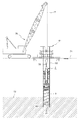
図7は、従来の中堀り装置2を用いた施工態様の概略を示す全体図である。
図8は、図7の中掘り装置2を示す拡大図である。
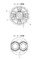
図9(a)は図8のA−A線に沿った断面図であり、図9(b)は図8のB−B線に沿った断面図である。
Hereinafter, a conventional digging apparatus will be described with reference to FIGS.
FIG. 7 is an overall view showing an outline of a construction mode using the conventional
FIG. 8 is an enlarged view showing the
9A is a cross-sectional view taken along line AA in FIG. 8, and FIG. 9B is a cross-sectional view taken along line BB in FIG.
従来の中掘り装置2は、ケーシングパイプ類62(ケーシングパイプや鋼管矢板など)を圧入するに際し該ケーシングパイプ類62の内側に挿入して中掘りするために用いられ、掘削に伴って生じた掘削土73をケーシングパイプ類62の外側(孔外)で排出できるようにクレーン76によって吊設可能に構成されている。以下、図8及び図9に基づいて従来の中掘り装置2の概略構成を説明する。
The
中掘り装置2は、上部装置2aと、下部装置2bと、反力伝達部材(内管4と外管6からなる断面矩形の略二重管構造)と、を含んで構成されている。上部装置2aは、下部装置2bによる掘削のための回転反力を確保するために、ケーシングパイプ類62の内壁に対し一時的に圧着固定される。下部装置2bは、上部装置2aの下方の地盤を掘削する役割を担う。反力伝達部材(内管4と外管6からなる略二重管構造)は、全体として伸縮自在に構成され、上部装置1bで確保した回転反力を下部装置2bで利用できるようにする役割を担う。
The
中掘り装置2の上部装置2aは、ピストンロッド75の先端が下部装置2bに連結された油圧シリンダ70と、ケーシングパイプ類62の内壁面に対し反力をとるための複数の圧着装置と、を含んで構成されている。各圧着装置は、圧着体12aと楔体12bとピン12cと油圧シリンダ15を有している。複数の圧着装置は、上部装置2aにおいて油圧シリンダ70を囲むように配置されている(図9(a)参照)。
The upper device 2a of the
圧着装置の圧着体12aは、中掘り装置2がケーシングパイプ類62の内側に挿入された状態で該ケーシングパイプ類62の内壁面に対し圧着される。これにより、回転駆動装置5の回転反力、油圧シリンダ70の圧入反力を、ケーシングパイプ類62に支持させることができる。
The crimping
中掘り装置2の下部装置2bは、ドリルシャフト30の外周に螺旋状に固設されたフィン32を備えたオーガースクリュー3と、オーガースクリュー3を回転させるための回転駆動装置5と、オーガースクリュー3を囲繞するように設けられたカプセルパイプ9と、を含んで構成される。オーガースクリュー3の先端部と回転駆動装置5の間隔Lは、常に一定の長さである。
The
カプセルパイプ9は底部側が開口しており、オーガースクリュー3のフィン32を囲繞するように設けられている。カプセルパイプ9の内側では、オーガースクリュー3が回転できるようになっており、オーガースクリュー3のフィン32によりリフトアップされてきた掘削土73を内側に収納する。カプセルパイプ内9に収容された掘削土73は、オーガースクリュー3のフィン32によって該カプセルパイプ9内に閉じ込められる。
なお、カプセルパイプ9は、上部装置2aの油圧シリンダ70の伸長する長さよりも長尺である。
The
The
上記構成の上部装置2aと下部装置2bは、上部装置2a側に設けられた油圧シリンダ70によって相互連結されている。
The upper device 2a and the
反力伝達部材(嵌合部材)は、断面四角形の内管4と、同じく断面四角形の外管6からなる略二重管構造で構成されている。外管6は上部装置2aに連結され、内管4は下部装置2bに連結されている。このような構成の反力伝達部材は、油圧シリンダ70の伸縮動作に従って自在に伸縮する一方で、上部装置1bで確保した回転反力を下部装置2bにおいて利用できるようにしている。
The reaction force transmission member (fitting member) has a substantially double tube structure including an inner tube 4 having a square section and an
上記中掘り装置2を用いた掘削では、はじめに、地上部に設置されたケーシング圧入装置61により圧入されたケーシングパイプ類62の内側に、クレーン76で吊設した中掘り装置2を挿入する。続いて、上部装置2aの圧着体12aをケーシングパイプ類62の内壁面に対し圧着させて、回転駆動装置5の回転反力および油圧シリンダ70の圧入反力を該ケーシングパイプ類62に支持させる。
In excavation using the
そして、反力をケーシングパイプ類62に支持させた状態で、上部装置2aの油圧シリンダ70を伸長させてオーガースクリュー3の先端部に押し込み作用を与え、下部装置2bの回転駆動装置5でオーガースクリュー3を回転させてその先端部で地盤を掘削する。掘削に伴って生じた掘削土73は、オーガースクリュー3でリフトアップさせて、該オーガースクリュー3を囲繞するカプセルパイプ9の内側に収納する。
Then, with the reaction force supported by the
そして、適当なタイミングで圧着体12aによる圧着状態を解除して中掘り装置2を引上げ、ケーシングパイプ類62の外側でオーガースクリュー3を逆回転させて、カプセルパイプ9内に収納された掘削土73をカプセルパイプ9から排出させるようになっている。
Then, the crimping state by the crimping
なお、中掘り装置2の操作にあたっては、下記工程A〜Dを繰り返し、下部装置2bのカプセルパイプ9の容量が一杯になるまで掘進する。
A) 上部装置2aの油圧シリンダ70を伸長させて下部装置2bを掘進させた後、
ケーシングパイプ類62に対する上部装置2aの圧着固定状態を解除する。
B) 非圧着状態で油圧シリンダ70を縮退させて上部装置2aを降下させる。
C) 降下した上部装置2aをケーシングパイプ類62に固定させて反力を確保する。
D) 上部装置2aの油圧シリンダ70を伸長させて下部装置2bを掘進させる。
In the operation of the
A) After extending the
The pressure-fixed state of the upper device 2a with respect to the
B) Lower the upper device 2a by retracting the
C) Secure the reaction force by fixing the lowered upper device 2a to the
D) Extending the
しかしながら、上述した従来の中掘り装置を用いた方法(いわゆる「スクリュードライバー工法」)には、排土性に関する点で問題があった。
すなわち、従来の中掘り装置でケーシングパイプ類内を掘削する際、特に固結性に乏しい砂礫・シルトといった地盤やそれらを対象とした水中掘削の際には、一般土砂と同様に掘削した掘削ずりをスクリューフィンを介して上昇させカプセルパイプ内に貯め圧縮効果を得ることで一時的に収納することも可能であった。ところが、カプセルパイプに底蓋がないため、ケーシング外へ掘削装置を吊り出す過程で、スクリューフィンを伝って滑落し、結果として、掘削した土を孔外へ排出することが困難で、掘進不能となっていた。
However, the above-described method using the conventional digging apparatus (so-called “screw driver method”) has a problem in terms of soil removal.
In other words, when excavating casing pipes with conventional digging equipment, especially when excavating sand and gravel with poor caking properties and underwater excavation targeting them, excavation drilling is performed in the same way as general earth and sand. It was also possible to temporarily store it by raising it through screw fins and storing it in a capsule pipe to obtain a compression effect. However, since the capsule pipe has no bottom lid, it slides down through the screw fins in the process of hanging the excavator out of the casing, and as a result, it is difficult to discharge the excavated soil out of the hole and it is impossible to dig. It was.
そこで、上述した従来技術の問題点に鑑み、本考案の目的は、従来工法(スクリュードライバー工法)で掘削が困難だった固結性に乏しい砂礫・シルトといった地盤やそれらを対象とした水中掘削においても、掘削ずりを途中で落とすこともなく、効率よく作業できるようにすることにある。 Therefore, in view of the above-mentioned problems of the prior art, the purpose of the present invention is in the ground such as gravel and silt with poor caking that was difficult to excavate by the conventional method (screw driver method) and underwater excavation for them. However, it is to be able to work efficiently without dropping excavation midway.
このような目的は、下記1)〜9)に記載の特徴によって達成される。 Such an object is achieved by the features described in 1) to 9) below.
1) 掘削を推進するにつれ掘削土(掘削ずり)を内部に取り込み、孔外へ排出するまでの間の該掘削土を格納するためのカプセルパイプ(41)を有し、該カプセルパイプ(41)の下端付近に地盤を掘削する掘削ビット(21)を配設した中掘り装置(1)において、該カプセルパイプ(21)の下端側に配設された底蓋としての蓋体(8)。 1) It has a capsule pipe (41) for storing the excavated soil until the excavated soil (drilling shear) is taken inside and discharged out of the hole as the excavation is promoted. A lid body (8) as a bottom lid disposed on the lower end side of the capsule pipe (21) in an intermediate digging device (1) in which a drill bit (21) for excavating the ground is disposed near the lower end of the capsule pipe (21).
2) 上記蓋体(8)が、カプセルパイプ(41)へ通ずる開口部(82)を開閉するシャッター(91)を有していて、このシャッター(91)が掘削時の装置の回転軸(掘削軸)にほぼ垂直な面上で回転スライドするように設けられていることを特徴とする掘削土格納用のカプセルパイプ(41)を有する中掘り装置(1)。 2) The lid (8) has a shutter (91) for opening and closing an opening (82) communicating with the capsule pipe (41), and this shutter (91) is a rotating shaft (excavation of the apparatus during excavation). An inside digging device (1) having a capsule pipe (41) for storing excavated soil, which is provided so as to rotate and slide on a plane substantially perpendicular to the shaft).
3) 掘削土格納用の上記カプセルパイプ(41)の下端にある回転スライド式の底蓋(8)が、地盤掘削時の回転方向に回転が加えられると、カプセルパイプ内に掘削推進につれ掘削土を格納することを自在にするように開口部(82)が設けられ、また、中掘り装置(1)の回転方向が逆になると、上記蓋体(8)のシャッター(91)が回転スライドして、上記開口部(82)を閉塞するようにされていることを特徴とする中掘り装置(1)。 3) When the rotating slide type bottom cover (8) at the lower end of the above-mentioned capsule pipe (41) for storing excavated soil is rotated in the direction of rotation during ground excavation, the excavated soil moves into the capsule pipe as the excavation proceeds. An opening (82) is provided so as to freely store, and when the direction of rotation of the digging device (1) is reversed, the shutter (91) of the lid (8) rotates and slides. An inside digging device (1) characterized in that the opening (82) is closed.
4) 上記回転スライド式のシャッター(91)が略半円状であることを特徴とする。また、掘削土取り込み用の開口部(82)が、掘削作業時において上記蓋体(8)が開放されているときに略半円状となっていることを特徴とする。 4) The rotary slide type shutter (91) is substantially semicircular. In addition, the opening (82) for taking excavated soil has a substantially semicircular shape when the lid (8) is opened during excavation work.
5) 上記回転スライド式の蓋体(8)の下面に配設(植設)されていることを特徴とする掘削刃(21)。この掘削刃(21)は、蓋体(8)の下面に直接配設されてもよく、或いは、何らかの部材(台座など)を介して間接的に蓋体(8)の下面に配設されてもよい。 5) The excavating blade (21), which is disposed (planted) on the lower surface of the rotary slide type lid (8). The excavating blade (21) may be directly disposed on the lower surface of the lid (8), or indirectly disposed on the lower surface of the lid (8) through some member (such as a pedestal). Also good.
6) 上記回転スライド式の蓋体(8)の下面側に配設された掘削刃(21)が、掘削時の開口部(82)に隣接する側に配設されていることを特徴とする掘削刃(21)。 6) The excavating blade (21) disposed on the lower surface side of the rotary slide type lid (8) is disposed on the side adjacent to the opening (82) during excavation. Drilling blade (21).
7) 上記回転スライド式の蓋体(8)の回転中心位置ないしその近傍に突設されていることを特徴とする掘削用のパイロットビット(22)。 7) A pilot bit (22) for excavation, characterized in that the pilot bit (22) is provided so as to project at or near the rotational center position of the rotary slide type lid (8).
8) 上記略半円状の回転スライド式の蓋体(8)に配設(植設)された掘削刃(21)が、掘削装置の回転力を介して装置下端の円断面より大きい径の円を形成することができ、掘削径を拡大自在に構成されていることを特徴とする中掘り装置(1)。 8) The excavating blade (21) disposed (planted) in the substantially semicircular rotary slide lid (8) has a diameter larger than the circular cross section at the lower end of the apparatus via the rotational force of the excavator. An inside digging apparatus (1) characterized in that it can form a circle and is configured to be capable of expanding a digging diameter.
9) 上記1)〜9)の特徴を有する中掘り装置(1)がクレーン吊り下げ式であり、ケーシングパイプ類(62)内に自身を固定する反力を有している。 9) The digging device (1) having the features 1) to 9) is a crane hanging type and has a reaction force for fixing itself in the casing pipes (62).
上記1)〜9)の特徴によれば、それぞれ、以下の作用効果が奏される。 According to the features 1) to 9), the following functions and effects are exhibited.
1) 掘削土格納用のカプセルパイプ(41)から掘削土が滑落しないように閉塞することが可能となり、その結果、高い排土効率を確保される。 1) It becomes possible to close the excavated soil so that it does not slide off from the capsule pipe (41) for storing excavated soil, and as a result, high soil removal efficiency is ensured.
2) 本願考案では、掘削軸とシャッター(91)の回転面とがほぼ直交するように設定されている。このように、蓋体(8)のシャッター(91)を掘削軸に垂直な面上で回転スライドさせることで、格納した土砂の排出時に、掘削土を格納用のカプセルパイプ(41)から排出する際に、蓋体(8)の開口部(82)を徐々に広く開けることができ、(従って、掘削軸に平行に開く従来のアースバケット式のような扉状の底蓋のように、掘削土の重みが底蓋ヒンジの回転方向に掛かり、その重みにより急激に開放されるようなことがなく)安全が確保でき、また(前記アースバケット式のように排出された掘削土が強い勢いで飛散することがないので)排出された掘削土を片付けやすい。 2) In the present invention, the excavation axis and the rotating surface of the shutter (91) are set so as to be substantially orthogonal. In this way, by rotating and sliding the shutter (91) of the lid (8) on a plane perpendicular to the excavation axis, the excavated soil is discharged from the capsule pipe (41) for storage when discharging the stored sediment. When opening, the opening (82) of the lid (8) can be gradually widened (and thus excavated like a door-shaped bottom lid like the conventional earth bucket type that opens parallel to the drilling axis) The weight of the soil is applied to the rotation direction of the bottom cover hinge, and it is not suddenly released by the weight, so safety can be secured, and the excavated soil discharged like the earth bucket type has a strong momentum It is easy to clear the excavated soil since it does not scatter.
3) 掘削軸にほぼ垂直に回転スライドさせる構成とすることで、中掘り装置(1)の回転力を援用して、地中で、蓋体(8)のシャッター(91)の開閉の遠隔操作(間接的操作)を行うことができる。 3) By using a structure that rotates and slides almost perpendicularly to the excavation shaft, it is possible to remotely control the opening and closing of the shutter (91) of the lid (8) in the ground using the rotational force of the digging device (1). (Indirect operation) can be performed.
4) 蓋体(8)および開口部(82)が略半円状で構成されることで、回転スライド式の蓋体(8)の掘削土の高い格納効率と、確実な操作性が得られる。 4) Since the lid (8) and the opening (82) are substantially semicircular, the rotary slide type lid (8) has high excavation soil storage efficiency and reliable operability. .
5) 上記回転スライド式の蓋体(8)下面に掘削刃(21)を直接又は間接に配設(植設)することで、中掘り装置(1)の機械長さ(クレーン(76)で吊り下げたときの機械高)を削減でき、省スペース化できる。更に、蓋体(8)下面から突出した状態で配設される掘削刃(21)は、それが地盤に突き刺さっている(もしくは、引っかかっている)状態にすれば、蓋体(8)に対し中掘り装置(1)が回転を加えた際に、開口(または閉塞)するようにシャッター(91)が回転スライドするための反力としての機能を兼備するようになり、(わざわざ、シャッター開閉のために専用の動力系を装置に加え、徒に構成を複雑にすることなく)、最小限の構成で合理的に蓋体(8)の操作性を向上させることができる。 5) By arranging (planting) the excavating blade (21) directly or indirectly on the lower surface of the rotary slide type lid (8), the machine length of the digging device (1) (crane (76)) Machine height when suspended) and space saving. Furthermore, the excavating blade (21) arranged in a state of protruding from the lower surface of the lid (8) can be placed against the lid (8) if it is stuck (or caught) into the ground. When the digging device (1) is rotated, it also has a function as a reaction force to rotate and slide the shutter (91) so that it opens (or closes). Therefore, the operability of the lid (8) can be improved reasonably with a minimum configuration without adding a dedicated power system to the apparatus and without complicating the configuration.
6) 上記掘削時の開口部(82)に隣接する側に掘削刃(21)を配設し(その点対称の位置には掘削刃を配設しない)でいることで、開口部(82)及びカプセルパイプ(41)内への土砂の取り込みが良くなる。 6) The excavating blade (21) is disposed on the side adjacent to the opening (82) at the time of excavation (the excavating blade is not disposed at the point-symmetrical position), so that the opening (82) And the uptake of earth and sand into the capsule pipe (41) is improved.
7) 上記回転スライド式の蓋体(8)の回転中心位置にパイロットビット(22)を突設させることで、中掘り装置の直進性を確保できる。特に、上記6)の構成のように、中掘り装置(1)の蓋体(8)下面片側にのみ掘削刃(21)が配設されている場合、中掘り装置(1)の回転中心の片側にのみ負荷がかかることになることから機械姿勢の傾きが懸念されるが、パイロットビット(22)が先行して地中に差し込まれていることで、回転中心が固定でき、ずれにくくなり、直進性が確保できる。 7) By making the pilot bit (22) project at the rotational center position of the rotary slide type lid (8), it is possible to ensure the straightness of the digging device. In particular, when the excavating blade (21) is disposed only on one side of the lower surface of the lid (8) of the digging device (1) as in the configuration of the above 6), the center of rotation of the digging device (1) Since the load is applied only to one side, there is a concern about the inclination of the machine posture, but the pilot bit (22) is inserted in the ground in advance, so the center of rotation can be fixed and it is difficult to shift, Straightness can be secured.
8) 上記略半円状のシャッター(91)に配設(植設)された掘削刃が、掘削装置の回転力を介して装置下端の円断面より大きい径の円を形成することができ、掘削径を拡大自在に構成されていることにより、例えば、老朽化したコンクリート護岸部に直接鋼管を打込み補強を行う工事において、以下のような効果を得ることができる。
供用中の既設コンクリート護岸部等を鋼管杭や鋼管矢板による壁状構造を用いて補強する場合、その性能を保持しながら補強工事を行う必要があり、コンクリート護岸部等に杭体の圧入に先行して砂置換工等を行うなどの施工手順は断面欠損の生じた状態の構造物と改変された地山を長期間放置することは望ましくない。
一方、上記の理由で直接杭体を圧入することが必要となる護岸の補強に際して、標準的な圧入工法は、機械による圧入力のみで杭の打込みを行うため、コンクリート護岸部への圧入が不能で適応できない。
それが本考案によれば、中掘り機(カプセルホウ(商標))に専用拡大ヘッドを装着し杭下端から突出させ、コンクリート等の硬質な圧入対象に削孔を施し、圧入を先導することができ、その結果、護岸構造の機能を保持しながら削孔することできるようになる。
また、回転切削によらない圧入施工が行えることから、鋼管矢板の圧入を行うことも可能となる。
8) The excavating blade disposed (planted) in the substantially semicircular shutter (91) can form a circle having a diameter larger than the circular cross section of the lower end of the apparatus through the rotational force of the excavator. Since the excavation diameter is configured to be freely expandable, for example, the following effects can be obtained in a construction in which a steel pipe is driven directly into an aged concrete revetment for reinforcement.
When reinforcing an existing concrete revetment part in service using a wall structure with steel pipe piles or steel pipe sheet piles, it is necessary to perform reinforcement work while maintaining its performance. In the construction procedure such as sand replacement work, it is not desirable to leave the structure with the cross-sectional defect and the modified natural ground for a long period of time.
On the other hand, when reinforcing a revetment where it is necessary to press-fit the pile body directly for the above reasons, the standard press-in method does not allow for press-fitting into the concrete revetment because the pile is driven only by mechanical pressure input. It cannot be adapted.
According to the present invention, it is possible to guide the press-fitting by attaching a special enlargement head to the digging machine (Capsule Haw ™) and projecting it from the lower end of the pile, drilling a hard press-fit object such as concrete. As a result, it becomes possible to drill holes while maintaining the function of the revetment structure.
Moreover, since the press-fitting work which does not depend on rotation cutting can be performed, it also becomes possible to press-fit a steel pipe sheet pile.
以下、添付図面に基づいて、本考案の具体的実施形態について詳細に説明する。
図1は、本考案の中掘り装置1を示す全体図である。
図2は、図1の中掘り装置の先端側(蓋体8の周囲)を示す拡大図である。
図3は、図1の中掘り装置の先端側を示す拡大図であって、右側面から見た状態を示している。なお、掘削ビット21の配設状態、作用等を明らかにするため、底部中央のパイロットビット22等の図示は省略してある。
図4(a)は蓋体8の上蓋81を示す底面図であり、図4(b)は下蓋をなすシャッター91を示す底面図である。
図5は図1の中掘り装置の底面図である。同図において、(a)は蓋体8のシャッター91が「開放位置」にある状態を示しており、(b)はシャッター91が「閉塞位置」にある状態を示している。
Hereinafter, specific embodiments of the present invention will be described in detail with reference to the accompanying drawings.
FIG. 1 is an overall view showing an
FIG. 2 is an enlarged view showing a front end side (around the lid body 8) of the digging apparatus of FIG.
FIG. 3 is an enlarged view showing the front end side of the digging apparatus of FIG. 1 and shows a state seen from the right side. In addition, in order to clarify the arrangement | positioning state, effect | action, etc. of the
FIG. 4A is a bottom view showing the
FIG. 5 is a bottom view of the digging apparatus of FIG. 4A shows a state where the
(中掘り装置の構成)
図1に示す本考案の中掘り装置1は、図8の従来の中掘り装置と同様に、上部装置1aと下部装置1bを含んで構成されている。上部装置1aの構成は、従来の中掘り装置2と同様であるので、同じ構成については同一符号を用い、その詳細な説明は省略する。下部装置1bについては、従来技術との相違点を中心に以下具体的に説明する。
(Configuration of the inside digging device)
An
本考案に係る中掘り装置1の下部装置1bは、掘削土を一時的に格納するためのカプセルパイプ(掘削土格納パイプ)41と、その内側で相対回転可能に設けられたスクリュー43と、該スクリューを回転させるための回転駆動装置5と、スクリュー軸44の先端側(図において下端側)に配設された蓋体8とを有している。蓋体8は上下に重なる2枚の蓋(上蓋81,下蓋91)を含んで構成され、その底面側に掘削ビット21、パイロットビット22を備えている。なお、蓋体8は、カプセルパイプ41の底蓋としても機能するものであるが、該カプセルパイプ41に対し固定されてはいない。
The
カプセルパイプ41内には、掘削を推進するにつれ掘削土が取り込まれ、孔外へ排出するまでの間の該掘削土が格納される。スクリュー43は、カプセルパイプ41内に取り込まれた掘削土をリフトアップさせるとともに、そのスクリューフィン45により掘削土をカプセルパイプ内に閉じ込める役割を担う。このスクリュー軸44の上端側は、従来と同様に回転駆動装置5に接続されている。
The excavated soil is taken into the
蓋体8は、スクリュー軸44の先端に固設された上蓋81と、該上蓋に対して所定角度範囲内で相対回転可能に設けられたシャッター(下蓋)91とを有している。上蓋81には、図4(a)に示すように、掘削土をカプセルパイプ41内に取り込むための開口部82が形成されている。下蓋としてのシャッター91は、上蓋81の開口部82を必要に応じて開放・閉塞する回転スライド式シャッターとして構成されている。
以下、蓋体8の詳細について説明する。
The
Hereinafter, the details of the
蓋体8の上蓋81は、スクリュー43の先端に固設され、該スクリューと一体回転する。上蓋81の開口部82は、図4(a)に示すように略半円状に形成されており、カプセルパイプ41への掘削土取込口として機能する。上蓋81の底面側には、下蓋としてのシャッター91が自在に回転スライドできるように設けられている。ただし、スライド式シャッター91の回転角度を規制するため、所定位置にブロック状のストッパー83が固設されている(図4(a)参照)。ストッパー83は上蓋81の底面側に突設されており、シャッター91の所定位置と当接するようになっている。
The
下蓋をなすシャッター91は、図5に示すように、上蓋81の開口部82を開放する「開放位置」と、該開口部を閉塞する「閉塞位置」との間の、所定角度範囲内で自在に回転スライドできるように設けられている。地盤の掘削を行っている間は「開放位置」にセットされ(図5(a))、カプセルパイプ41内の掘削土を孔外へ排出する際には搬送中「閉塞位置」にセットされる(図5(b))。このようなシャッター91の位置決め(回転スライド)は、後述するようにスクリュー43の回転駆動方向を変えることにより、自在に制御することができる。
As shown in FIG. 5, the
シャッター91は、底面側(図4(b))から見て、略半円状の形状を有し、上蓋81の開口部82より一回り大きい面積を有する。シャッター91は、その中央に回転体92を一体的に備えている。回転体92は、上蓋81に対して回転自在に設けられている。回転体92の底部には、図2に示すように、パイロットビット22が植設されている。パイロットビット22の配設位置は特に限定されないが、シャッター91の回転中心位置またはその近傍に突設することが好ましい。
The
回転体92の周囲には、略半円状のスライドパネル94が一体回転可能に設けられている。このスライドパネル94は、スクリュー43の回転軸(すなわち掘削軸)とほぼ直交する面上で回転スライドするように、回転体92に対し一体的に設けられている。
A substantially
略半円状スライドパネル94の底面側の一端には、掘削ビット21が設けられている。この掘削ビット21は、図3に示すように、掘進方向(軸方向)に対して傾斜させて設けられており、地盤を掘削するとともに、掘削土を上方(上蓋81の開口部82の方向)へ掬い上げる役割を担っている。したがって、シャッター91が「開放位置」にある状態において、掘削ビット21が開口部82直下の領域へ突き出るように(図3,図5(a)参照)、該掘削ビットを傾斜させて(正転方向に傾斜させた状態で)固設することが好ましい。また掘削時において、効率的に掘削土を開口部82から取り込むために、該開口部直下の領域に掘削ビット21が追随するように、図5(a)に示す如く開口部82に隣接する側に掘削ビット21を配設することが好ましい。
An
(中掘り装置の作用)
次に、上記構成の中掘り装置1の作用について説明する。
(Operation of the digging device)
Next, the operation of the
はじめに、地盤の掘削を開始するまでの前作業について、図7に示す施行態様を援用して説明する。
中掘り装置1を用いた掘削では、はじめに、地上部に設置されたケーシング圧入装置61により圧入されたケーシングパイプ類62の内側に、クレーン76で吊設した中掘り装置1を挿入する。続いて、上部装置1aの圧着体12aをケーシングパイプ類62の内壁面に対し圧着させて、回転駆動装置5の回転反力および油圧シリンダ70の圧入反力を該ケーシングパイプ類62に支持させる。そして、反力をケーシングパイプ類62に支持させた状態で、上部装置1aの油圧シリンダ70を伸長させて、スクリュー43を介して先端の掘削ビット21,パイロットビット22に押し込み作用を与え、下部装置1bの回転駆動装置5でスクリュー43を回転(正転)させる。
First, the pre-work up to the start of excavation of the ground will be described with the aid of the enforcement mode shown in FIG.
In excavation using the
この際、シャッター91は図5(a)に示す「開放位置」にあり、上蓋81の開口部82は開放されている。なお、回転駆動開始時(掘削開始時)にシャッター91が「閉塞位置」にある場合には(又は開口部82が半開きの場合には)、スクリュー43と上蓋81が一体回転する一方で、シャッター91だけが地盤の抵抗を受けほぼ静止した状態になる。その結果、シャッター91が相対的に回転スライドするので、該シャッターを「開放位置」にセットすることができる。なお、シャッターが「開放位置」まで回転すると、図5(a)に示すように、上蓋81から突き出たストッパー83がシャッター91の一端に当接するので、開放位置を越えてスライドすることはない。
At this time, the
そして、図5(a)の「開放位置」にある状態でスクリュー43を正転させている間は、シャッター91が上蓋81のストッパー83の干渉を受ける結果、スクリュー43と上蓋81とシャッター91の全体が一体回転する。その結果、シャッター91の底面側に設けられた掘削ビット21、パイロットビット22により地盤を掘削することができる。
While the
地盤を掘削している間は、掘削ビット21が、開口部82直下の領域を追随するようにして、掘削径の範囲内を旋回し続ける。したがって、掘削に伴って生じた掘削土は、傾斜した掘削ビット21によって掬い上げられ(図3参照)、そのまま上蓋81の開口部82を介してカプセルパイプ41内に取り込まれる。さらにカプセルパイプ41内では、掘削土はスクリューフィン45でリフトアップされ、該カプセルパイプ内に収納される。
While excavating the ground, the
そして、掘削を続けてカプセルパイプ41の容量が一杯になったら、スクリュー43を逆転させる。すると、スクリュー43と上蓋81が逆方向に一体回転する一方で、シャッター91だけが地盤の抵抗を受けほぼ静止した状態になる。その結果、シャッター91が相対的に回転スライドして、図5(b)の「閉塞位置」にセットすることができる。なお、シャッターが「閉塞位置」まで回転すると、上蓋81から突き出たストッパー83がシャッター91の一端に当接するので、閉塞位置を越えてスライドすることはない。
Then, when the excavation is continued and the capacity of the
続いて、上部装置1aにおける圧着状態を解除して中掘り装置1を引上げ、ケーシングパイプ類62の外側でスクリュー3を逆回転させて、カプセルパイプ9内に収納された掘削土73をカプセルパイプ9から排出させる。
Subsequently, the crimping state in the
(中掘り装置の変形例)
以上、本考案の中掘り装置について説明したが、本考案の構成は上記実施形態に限定されるものではなく、請求の範囲内で種々の改変が可能である。
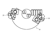
たとえば、蓋体8の底面側に設ける掘削ビットは、図4(b)に示す固定式の掘削ビット21に限定されず、これに代えて(或いは併用して)、図6に示すようなスイング自在の掘削ビット23を採用することもできる。このスイング式掘削ビット23は掘削径を拡大自在に構成されており、回転駆動装置5を正転駆動させることにより、周辺地盤の抵抗を受けて拡径位置へスイングし、逆転駆動させることにより縮径位置へスイングする。したがって、中掘り装置の回転力を介して装置下端の円断面より大きい径の円を形成することができる。
(Modified example of medium digging equipment)
Although the present invention has been described above, the configuration of the present invention is not limited to the above embodiment, and various modifications can be made within the scope of the claims.
For example, the excavation bit provided on the bottom surface side of the
(中掘り装置の効果)
上述した中掘り装置によれば、従来工法(スクリュードライバー工法)で掘削が困難だった固結性に乏しい砂礫・シルトといった地盤やそれらを対象とした水中掘削においても、掘削ずりを途中で落とすこともなく、効率よく作業ができるようになるという優れた効果が奏される。
(Effect of medium digging equipment)
According to the above-mentioned digging equipment, the excavation shear can be dropped in the middle of the ground such as gravel and silt with poor caking that was difficult to excavate by the conventional method (screw driver method) and underwater excavation targeting them. There is also an excellent effect of being able to work efficiently.
1 中掘り装置(本願考案)
1a 上部装置
1b 下部装置
2 中掘り装置(従来技術)
2a 上部装置
2b 下部装置
3 オーガースクリュー
4 内管
5 回転駆動装置
6 外管
8 蓋体
9 カプセルパイプ
11 プレート
12a 圧着体
12b 楔体
12c ピン
15 油圧シリンダ
21 掘削ビット
22 パイロットビット
23 掘削ビット
30 ドリルシャフト
31 掘削ビット(掘削ヘッド)
32 フィン
41 カプセルパイプ(掘削土格納パイプ)
43 スクリュー
44 スクリュー軸
45 スクリューフィン
61 ケーシング圧入装置
62 ケーシングパイプ類
70 油圧シリンダ
71 地盤
72 硬質地盤
73 スライム
75 ピストンロッド
76 クレーン
77 ワイヤー
78 フック
81 上蓋
82 開口部
83 ストッパー
91 シャッター(下蓋)
92 回転体
94 スライドパネル
1. Medium digging device (this device)
32
43
92
Claims (2)
掘削を推進するにつれ生じた掘削土を内部に取り込み、孔外へ排出するまで格納するためのカプセルと、
前記カプセルの底蓋をなす蓋体と、
を有することを特徴とする中掘り装置。 A drill bit for drilling the ground,
Capsule for storing the excavated soil generated as propelling is taken into the interior and storing it until it is discharged out of the hole,
A lid that forms the bottom lid of the capsule;
An inside digging apparatus characterized by comprising:
Priority Applications (1)
| Application Number | Priority Date | Filing Date | Title |
|---|---|---|---|
| JP2008005553U JP3145827U (en) | 2008-08-08 | 2008-08-08 | Medium digging equipment |
Applications Claiming Priority (1)
| Application Number | Priority Date | Filing Date | Title |
|---|---|---|---|
| JP2008005553U JP3145827U (en) | 2008-08-08 | 2008-08-08 | Medium digging equipment |
Publications (1)
| Publication Number | Publication Date |
|---|---|
| JP3145827U true JP3145827U (en) | 2008-10-23 |
Family
ID=43295575
Family Applications (1)
| Application Number | Title | Priority Date | Filing Date |
|---|---|---|---|
| JP2008005553U Expired - Lifetime JP3145827U (en) | 2008-08-08 | 2008-08-08 | Medium digging equipment |
Country Status (1)
| Country | Link |
|---|---|
| JP (1) | JP3145827U (en) |
Cited By (5)
| Publication number | Priority date | Publication date | Assignee | Title |
|---|---|---|---|---|
| WO2011142367A1 (en) * | 2010-05-10 | 2011-11-17 | 住友金属工業株式会社 | Steel wall and construction method for steel wall |
| JP2013147926A (en) * | 2011-12-21 | 2013-08-01 | Yokoyama Kiso Koji:Kk | Tubular pile driving method, excavation method, medium digging device, and gripping device |
| JP2017128910A (en) * | 2016-01-20 | 2017-07-27 | 日本基礎技術株式会社 | Soil discharging adapter, drilling device and soil discharging collection system |
| CN113474534A (en) * | 2018-12-07 | 2021-10-01 | 理查德戈伦企业有限责任公司 | Automatic hand shovel with auger |
| EP4463598A1 (en) | 2022-01-13 | 2024-11-20 | Geopier Foundation Company, Inc. | Methods and apparatus for building expanded shaft augured foundation elements |
-
2008
- 2008-08-08 JP JP2008005553U patent/JP3145827U/en not_active Expired - Lifetime
Cited By (10)
| Publication number | Priority date | Publication date | Assignee | Title |
|---|---|---|---|---|
| WO2011142367A1 (en) * | 2010-05-10 | 2011-11-17 | 住友金属工業株式会社 | Steel wall and construction method for steel wall |
| CN102782219A (en) * | 2010-05-10 | 2012-11-14 | 住友金属工业株式会社 | Steel wall and construction method for steel wall |
| JP5321741B2 (en) * | 2010-05-10 | 2013-10-23 | 新日鐵住金株式会社 | Steel wall and construction method of steel wall |
| CN102782219B (en) * | 2010-05-10 | 2015-04-01 | 新日铁住金株式会社 | Steel wall and construction method for steel wall |
| JP2013147926A (en) * | 2011-12-21 | 2013-08-01 | Yokoyama Kiso Koji:Kk | Tubular pile driving method, excavation method, medium digging device, and gripping device |
| JP2017128910A (en) * | 2016-01-20 | 2017-07-27 | 日本基礎技術株式会社 | Soil discharging adapter, drilling device and soil discharging collection system |
| CN113474534A (en) * | 2018-12-07 | 2021-10-01 | 理查德戈伦企业有限责任公司 | Automatic hand shovel with auger |
| EP4463598A1 (en) | 2022-01-13 | 2024-11-20 | Geopier Foundation Company, Inc. | Methods and apparatus for building expanded shaft augured foundation elements |
| EP4463598A4 (en) * | 2022-01-13 | 2025-04-16 | Geopier Foundation Company, Inc. | Methods and apparatus for building expanded shaft augured foundation elements |
| AU2023207990B2 (en) * | 2022-01-13 | 2025-10-09 | Geopier Foundation Company, Inc. | Methods and apparatus for building expanded shaft augured foundation elements |
Similar Documents
| Publication | Publication Date | Title |
|---|---|---|
| JP5605940B2 (en) | Construction management method of root-fixed bulb part and expansion excavator used therefor | |
| JP3145827U (en) | Medium digging equipment | |
| JP2001032274A (en) | Method and device for placing concrete pile and enlarged head | |
| JP6319935B2 (en) | Tubing pile driving method | |
| JP2724548B2 (en) | 2-stage enlarged head | |
| JP5380064B2 (en) | Pile hole drilling method and pile hole drilling head | |
| JPH094353A (en) | Vertical hole excavating device | |
| JP3856656B2 (en) | Rotating drive for excavation | |
| JP2021042580A (en) | Excavator and method for constructing monopile foundation | |
| JP4501249B2 (en) | Steel pipe pile and its construction method | |
| JP2006083573A (en) | All casing method and its apparatus | |
| JP3991311B2 (en) | Method of burying excavation rod and ready-made pile | |
| JPH0726867A (en) | Bucket self-lifting excavator | |
| JP4137165B2 (en) | Excavation and earthing method, caisson press-fitting method and diameter-excavating device | |
| JP2003161091A (en) | Large-diameter excavator | |
| JP2012140787A (en) | Construction method of pile body and casing pipe used for the same, and foundation structure constructed thereby | |
| JP7761903B2 (en) | How to construct cast-in-place concrete piles | |
| JPH11131961A (en) | Casing shaft construction method and device therefor | |
| JP2005002635A (en) | Foundation pile and its manufacturing method | |
| JP2980855B2 (en) | Caisson laying method and its equipment | |
| JP3004267B1 (en) | Drilling rig | |
| JP2003041877A (en) | Excavation head | |
| JP2003096772A (en) | Screw-in type steel pipe pile and its construction method | |
| JP4612660B2 (en) | Excavation apparatus and excavation method | |
| JP2014034763A (en) | Widening excavation method |
Legal Events
| Date | Code | Title | Description |
|---|---|---|---|
| RD04 | Notification of resignation of power of attorney |
Free format text: JAPANESE INTERMEDIATE CODE: A7424 Effective date: 20080908 |
|
| R150 | Certificate of patent or registration of utility model |
Free format text: JAPANESE INTERMEDIATE CODE: R150 |
|
| FPAY | Renewal fee payment (event date is renewal date of database) |
Free format text: PAYMENT UNTIL: 20111001 Year of fee payment: 3 |
|
| FPAY | Renewal fee payment (event date is renewal date of database) |
Free format text: PAYMENT UNTIL: 20111001 Year of fee payment: 3 |
|
| FPAY | Renewal fee payment (event date is renewal date of database) |
Free format text: PAYMENT UNTIL: 20121001 Year of fee payment: 4 |
|
| FPAY | Renewal fee payment (event date is renewal date of database) |
Free format text: PAYMENT UNTIL: 20121001 Year of fee payment: 4 |
|
| FPAY | Renewal fee payment (event date is renewal date of database) |
Free format text: PAYMENT UNTIL: 20131001 Year of fee payment: 5 |
|
| R250 | Receipt of annual fees |
Free format text: JAPANESE INTERMEDIATE CODE: R250 |
|
| R250 | Receipt of annual fees |
Free format text: JAPANESE INTERMEDIATE CODE: R250 |
|
| R250 | Receipt of annual fees |
Free format text: JAPANESE INTERMEDIATE CODE: R250 |
|
| R250 | Receipt of annual fees |
Free format text: JAPANESE INTERMEDIATE CODE: R250 |
|
| R250 | Receipt of annual fees |
Free format text: JAPANESE INTERMEDIATE CODE: R250 |
|
| EXPY | Cancellation because of completion of term |