JP3145976U - High pressure gas supply device - Google Patents

High pressure gas supply device Download PDF

Info

Publication number
JP3145976U
JP3145976U JP2008005743U JP2008005743U JP3145976U JP 3145976 U JP3145976 U JP 3145976U JP 2008005743 U JP2008005743 U JP 2008005743U JP 2008005743 U JP2008005743 U JP 2008005743U JP 3145976 U JP3145976 U JP 3145976U
Authority
JP
Japan
Prior art keywords
pressure gas
gas supply
exhaust
fastener
bag body
Prior art date
Legal status (The legal status is an assumption and is not a legal conclusion. Google has not performed a legal analysis and makes no representation as to the accuracy of the status listed.)
Expired - Fee Related
Application number
JP2008005743U
Other languages
Japanese (ja)
Inventor
武彦 森
Original Assignee
テイクハート株式会社
Priority date (The priority date is an assumption and is not a legal conclusion. Google has not performed a legal analysis and makes no representation as to the accuracy of the date listed.)
Filing date
Publication date
Application filed by テイクハート株式会社 filed Critical テイクハート株式会社
Priority to JP2008005743U priority Critical patent/JP3145976U/en
Application granted granted Critical
Publication of JP3145976U publication Critical patent/JP3145976U/en
Anticipated expiration legal-status Critical
Expired - Fee Related legal-status Critical Current

Links

Images

Landscapes

  • Accommodation For Nursing Or Treatment Tables (AREA)

Abstract

【課題】排気管路の排気を除湿して供給管路に循環供給し装置本体内の除湿を行うようにした高圧気体供給装置を提供する。
【解決手段】装置本体50内に加圧源40から高圧気体を送り込む供給管路36と装置本体内からの排気を加圧源に循環する排気管路37とを有する加圧機構を設けると共に、供給管路36と排気管路37とをエアドライヤ38を具備する除湿管路39で連結し、排気管路37の排気を除湿して供給管路36に循環供給し装置本体50内の除湿を行うようにした。
【選択図】図1
A high-pressure gas supply device that dehumidifies exhaust gas from an exhaust pipe and circulates and supplies it to a supply pipe to dehumidify the inside of the main body of the apparatus.
A pressurization mechanism having a supply pipe line for sending high-pressure gas from a pressurization source into the apparatus main body and an exhaust pipe line for circulating exhaust from the apparatus main body to the pressurization source is provided. The supply line 36 and the exhaust line 37 are connected by a dehumidification line 39 having an air dryer 38, and the exhaust in the exhaust line 37 is dehumidified and circulated and supplied to the supply line 36 to dehumidify the apparatus main body 50. I did it.
[Selection] Figure 1

Description

本考案は、大気圧以上の高い圧力で空気以上の酸素濃度の濃い気体を人又は動物に供給して、心身の疲労の回復、美容および健康の増進、新陳代謝の増進によるダイエット効果、生活習慣病の予防、視力の回復向上等を期待することができる高圧気体供給装置に関する。   The present invention supplies a human or animal with a gas with a high oxygen concentration above air at high pressure above atmospheric pressure to recover mental and physical fatigue, improve beauty and health, increase dietary effects, and lifestyle-related diseases. The present invention relates to a high-pressure gas supply apparatus that can be expected to prevent eyesight and improve eyesight recovery.

従来、高山病治療装置として、通気性と高圧気体の内圧に対して耐圧性を有する強度の大きい外側袋体内に、高圧気体に対して非通気性を有する柔軟な強度の小さい内側袋体を収容して、内側袋体内に加圧源から高圧気体を送り込み、膨らんだ内側袋体の圧力及び形状を外側袋体が負担し維持するようになした高圧気体供給装置は知られている(特許文献1参照。)。   Conventionally, as a device for treating altitude sickness, a flexible low strength inner bag body that is non-breathable with respect to high pressure gas is accommodated in a large strength outer bag body that has air permeability and pressure resistance against the internal pressure of high pressure gas. A high-pressure gas supply device is known in which high-pressure gas is fed from a pressure source into the inner bag body and the outer bag body bears and maintains the pressure and shape of the inflated inner bag body (Patent Literature). 1).

また、治療室内の内圧を高圧と低圧に交互に切り替えうる切り替え手段を備え、全体が非通気性のEVA樹脂、ウレタン、ナイロン、塩化ビニルからなる一体の可撓性のチャンバからなる高気圧式酸素供給装置において、患者の出入口部分を2重構造にした高圧気体供給装置も知られている(特許文献2参照。)。   In addition, it is equipped with switching means that can alternately switch the internal pressure in the treatment room between high and low pressure, and the high-pressure oxygen supply consists of a single, flexible chamber made entirely of non-breathable EVA resin, urethane, nylon, and vinyl chloride. As a device, a high-pressure gas supply device having a double entrance / exit portion of a patient is also known (see Patent Document 2).

特公平4−20354号公報Japanese Patent Publication No. 4-20354 特許第3720032号公報Japanese Patent No. 3720032

従来装置の場合、内側袋体内の湿度が利用者の息や発汗により上がると、更に利用者の息や発汗が上がり、湿度が上昇する悪循環により、袋内の湿度が70%以上にもなり、利用者が快適な環境で利用できない課題があった。   In the case of the conventional device, when the humidity in the inner bag body rises due to the breath and sweat of the user, the breath and sweat of the user rises further, and the humidity in the bag becomes 70% or more due to a vicious cycle in which the humidity rises. There was a problem that users could not use in a comfortable environment.

そこで本考案は、請求項1に記載のように、高圧気体供給装置において、装置本体内に加圧源から酸素を富化した高圧気体を送り込む供給管路と装置本体内からの排気を加圧源に循環する排気管路とを有する加圧機構を設けると共に、供給管路と排気管路とをエアドライヤを具備する除湿管路で連結し、排気管路の排気を除湿して供給管路に循環供給し装置本体内の除湿を行うようにした高圧気体供給装置を提供しようとするものである。   In view of this, the present invention provides a high-pressure gas supply apparatus as described in claim 1, wherein a supply line for feeding high-pressure gas enriched with oxygen from a pressure source into the apparatus main body and an exhaust from the apparatus main body are pressurized. A pressurizing mechanism having an exhaust line circulating in the source, and connecting the supply line and the exhaust line with a dehumidification line having an air dryer to dehumidify the exhaust gas in the supply line. An object of the present invention is to provide a high-pressure gas supply device that circulates and dehumidifies the inside of the device body.

また、本考案は、請求項2に記載のように、請求項1に記載の高圧気体供給装置において、エアドライヤにより除湿した後の空気の温度を所定の温度に調整可能に設けてなる高圧気体供給装置を提供しようとするものである。   Further, according to the present invention, as described in claim 2, the high-pressure gas supply apparatus according to claim 1, wherein the temperature of the air after dehumidification by the air dryer is provided to be adjustable to a predetermined temperature. The device is to be provided.

また、本考案は、請求項3に記載のように、請求項2に記載の高圧気体供給装置において、エアドライヤの除湿後の空気の温度を所定の温度範囲に制御可能に設けてなる高圧気体供給装置を提供しようとするものである。   Further, according to the present invention, as described in claim 3, the high-pressure gas supply apparatus according to claim 2, wherein the air temperature after dehumidification of the air dryer is provided so as to be controllable within a predetermined temperature range. The device is to be provided.

また、本考案は、請求項4に記載のように、請求項2又は3に記載の高圧気体供給装置において、所定の温度が摂氏15乃至28度の範囲内の温度からなる高圧気体供給装置を提供しようとするものである。   Further, according to the present invention, as described in claim 4, the high-pressure gas supply device according to claim 2 or 3, wherein the high-pressure gas supply device has a temperature within a range of 15 to 28 degrees Celsius. It is something to be offered.

また、本考案は、請求項5に記載のように、請求項1乃至4のいずれかに記載の高圧気体供給装置において、エアドライヤが毎分20〜100リットルの排気管路の排気を除湿して供給管路に循環供給するようにした高圧気体供給装置を提供しようとするものである。   Further, according to the present invention, as described in claim 5, in the high-pressure gas supply device according to any one of claims 1 to 4, the air dryer dehumidifies exhaust from an exhaust line of 20 to 100 liters per minute. An object of the present invention is to provide a high-pressure gas supply device that circulates and supplies a supply pipe.

また、本考案は、請求項6に記載のように、請求項1乃至5のいずれかに記載の高圧気体供給装置において、エアドライヤが装置本体内の湿度を20〜60%に除湿するようにした高圧気体供給装置を提供しようとするものである。   Further, according to the present invention, as described in claim 6, in the high-pressure gas supply device according to any one of claims 1 to 5, the air dryer dehumidifies the humidity in the device main body to 20 to 60%. An object of the present invention is to provide a high-pressure gas supply device.

また、本考案は、請求項7に記載のように、請求項1乃至6のいずれかに記載の高圧気体供給装置において、排気管路からエアドライヤに排気を送るポンプを設けてなる高圧気体供給装置を提供しようとするものである。   Further, according to the present invention, as described in claim 7, the high-pressure gas supply device according to any one of claims 1 to 6, wherein a high-pressure gas supply device including a pump for sending exhaust gas from an exhaust pipe line to an air dryer is provided. Is to provide.

また、本考案は、請求項8に記載のように、請求項7に記載の高圧気体供給装置において、ポンプ内を流れる排気の量を調節してエアドライヤによる除湿又は温度を調整可能に設けてなる高圧気体供給装置を提供しようとするものである。   Further, according to the present invention, as described in claim 8, in the high-pressure gas supply device according to claim 7, the dehumidification by the air dryer or the temperature can be adjusted by adjusting the amount of exhaust flowing through the pump. An object of the present invention is to provide a high-pressure gas supply device.

また、本考案は、請求項9に記載のように、請求項1乃至8のいずれかに記載の高圧気体供給装置において、装置本体が、折り畳み可能な柔軟性を有する内側袋体と、通気性を有する耐圧性の外側袋体とからなり、内側袋体の出入口が高圧気体に対して全長に渡って微通気性を有する高圧気体供給装置を提供しようとするものである。   Further, according to a ninth aspect of the present invention, in the high-pressure gas supply device according to any one of the first to eighth aspects, the device main body has a foldable inner bag body and a breathable property. It is intended to provide a high-pressure gas supply device that has a pressure-resistant outer bag body having an inner bag body, and the inlet / outlet of the inner bag body has micro-breathability over the entire length with respect to the high-pressure gas.

また、本考案は、請求項10に記載のように、請求項9に記載の高圧気体供給装置において、内側袋体の出入口に微通気性を有する微通気性ファスナーを設けてなる高圧気体供給装置を提供しようとするものである。   Further, according to the present invention, as described in claim 10, in the high-pressure gas supply apparatus according to claim 9, the high-pressure gas supply apparatus is provided with a micro-breathable fastener having micro-breathability at the entrance and exit of the inner bag body. Is to provide.

また、本考案は、請求項11に記載のように、請求項10に記載の高圧気体供給装置において、微通気性ファスナーがファスナー全体に渡ってほぼ均等な通気性を有する高圧気体供給装置を提供しようとするものである。   Further, the present invention provides a high-pressure gas supply device according to claim 10, wherein the micro-breathable fastener has a substantially uniform air permeability over the entire fastener. It is something to try.

また、本考案は、請求項12に記載のように、請求項10又は11に記載の高圧気体供給装置において、微通気性ファスナーの微通気性が毎分10リットル乃至120リットルからなる高圧気体供給装置を提供しようとするものである。   Further, according to the present invention, as described in claim 12, in the high-pressure gas supply device according to claim 10 or 11, the high-pressure gas supply in which the micro-breathable fastener has a micro-breathability of 10 to 120 liters per minute. The device is to be provided.

また、本考案は、請求項13に記載のように、請求項12に記載の高圧気体供給装置において、微通気性ファスナーの微通気性が毎分30リットル乃至50リットルからなる高圧気体供給装置を提供しようとするものである。   Further, according to the present invention, as described in claim 13, the high pressure gas supply device according to claim 12, wherein the micro breathability of the micro breathable fastener is 30 to 50 liters per minute. It is something to be offered.

また、本考案は、請求項14に記載のように、請求項10乃至13のいずれかに記載の高圧気体供給装置において、微通気性ファスナーの周囲に伸張弾力性を有するファスナー取付袋部分を設けてなる高圧気体供給装置を提供しようとするものである。   Further, according to the present invention, as described in claim 14, in the high-pressure gas supply device according to any one of claims 10 to 13, a fastener attachment bag portion having stretch elasticity is provided around the slightly breathable fastener. A high-pressure gas supply device is provided.

また、本考案は、請求項15に記載のように、請求項10乃至14のいずれかに記載の高圧気体供給装置において、加圧機構の加圧源から高圧気体を微通気性ファスナーの通気性を補って供給してなる高圧気体供給装置を提供しようとするものである。   Further, according to the present invention, as described in claim 15, the high-pressure gas supply device according to any one of claims 10 to 14, wherein the high-pressure gas is supplied from a pressurization source of the pressurization mechanism to the breathability of the micro-breathable fastener. It is intended to provide a high-pressure gas supply device that supplements the supply.

また、本考案は、請求項16に記載のように、請求項1乃至12のいずれかに記載の高圧気体供給装置において、装置本体の内部が1.1気圧乃至1.5気圧で酸素濃度が25%乃至50%になることからなる高圧気体供給装置を提供しようとするものである。   Further, according to the present invention, as described in claim 16, in the high-pressure gas supply device according to any one of claims 1 to 12, the inside of the apparatus main body has an oxygen concentration of 1.1 to 1.5 atm. An object of the present invention is to provide a high-pressure gas supply device consisting of 25% to 50%.

本考案に係る高圧気体供給装置によれば、請求項1に記載のように、高圧気体供給装置において、装置本体内に加圧源から酸素を富化した高圧気体を送り込む供給管路と装置本体内からの排気を加圧源に循環する排気管路とを有する加圧機構を設けると共に、供給管路と排気管路とをエアドライヤを具備する除湿管路で連結し、排気管路の排気を除湿して供給管路に循環供給し装置本体内の除湿を行うようにした構成を有することにより、従来装置が、装置本体内の湿度が利用者の息や発汗により上がると共に更に利用者の息や発汗が上がる悪循環により、袋内の湿度が70%以上にもなり、利用者が快適な環境で利用できないのに対し、本考案装置によれば、装置本体の湿気を含んだ排気を除湿管路においてエアドライヤで除湿して供給管路を介して装置本体内に供給することができるから、装置本体内の高圧気体を快適な湿度に維持することができる効果がある。     According to the high-pressure gas supply apparatus according to the present invention, as in claim 1, in the high-pressure gas supply apparatus, a supply conduit for feeding high-pressure gas enriched with oxygen from a pressure source into the apparatus main body and the apparatus main body A pressurizing mechanism having an exhaust pipe that circulates the exhaust from the inside to a pressurization source is provided, and the supply pipe and the exhaust pipe are connected by a dehumidification pipe that includes an air dryer, and the exhaust pipe is exhausted. By having a configuration in which dehumidification and circulation supply to the supply pipe are performed to dehumidify the inside of the apparatus body, the conventional apparatus increases the humidity in the apparatus body due to user breathing and sweating, and further increases the user's breathing. Due to the vicious cycle of rising and sweating, the humidity in the bag becomes 70% or more, and the user cannot use it in a comfortable environment. Supply pipe dehumidified with an air dryer on the road Because it can be fed into the apparatus main body via a, there is an effect that it is possible to maintain the high pressure gas in the apparatus main body to a comfortable humidity.

また、本考案は、請求項2に記載のように、請求項1に記載の高圧気体供給装置において、エアドライヤにより除湿した後の空気の温度を所定の温度に調整可能に設けてなる構成を有することにより、加圧機構からの高圧気体に除湿管路から温度調整した除湿空気を供給することによって装置本体内の温度を快適にすることができる効果がある。   Further, according to the present invention, as described in claim 2, in the high-pressure gas supply device according to claim 1, the temperature of the air after being dehumidified by an air dryer is provided so as to be adjustable to a predetermined temperature. Thus, there is an effect that the temperature in the apparatus main body can be made comfortable by supplying the dehumidified air whose temperature is adjusted from the dehumidifying conduit to the high-pressure gas from the pressurizing mechanism.

また、本考案は、請求項3に記載のように、請求項2に記載の高圧気体供給装置において、エアドライヤの除湿後の空気の温度を所定の温度範囲に制御可能に設けてなる構成を有することにより、除湿した空気の温度を所定の温度に制御して装置本体内の温度を快適な温度に制御することができる効果がある。   Moreover, this invention has the structure which provides the high-pressure gas supply apparatus of Claim 2 so that control of the temperature of the air after dehumidification of an air dryer is controllable to a predetermined temperature range as described in Claim 3. Thus, there is an effect that the temperature of the dehumidified air can be controlled to a predetermined temperature to control the temperature in the apparatus main body to a comfortable temperature.

また、本考案は、請求項4に記載のように、請求項2又は3に記載の高圧気体供給装置において、所定の温度が摂氏15乃至28度の範囲内の温度からなる構成を有することにより、装置本体内の除湿した空気を利用者が快適と感ずる摂氏15乃至28度の範囲内の温度に制御することができる効果がある。   Further, according to the present invention, as described in claim 4, the high-pressure gas supply device according to claim 2 or 3 has a configuration in which the predetermined temperature is a temperature within a range of 15 to 28 degrees Celsius. There is an effect that the dehumidified air in the apparatus main body can be controlled to a temperature within a range of 15 to 28 degrees Celsius that the user feels comfortable.

また、本考案は、請求項5に記載のように、請求項1乃至4のいずれかに記載の高圧気体供給装置において、エアドライヤが毎分20〜100リットルの排気管路の排気を除湿して供給管路に循環供給するようにした構成を有することにより、装置本体内の除湿した空気を利用者の快適とする温度にすることができる効果がある。   Further, according to the present invention, as described in claim 5, in the high-pressure gas supply device according to any one of claims 1 to 4, the air dryer dehumidifies exhaust from an exhaust line of 20 to 100 liters per minute. By having the configuration in which the supply pipe is circulated and supplied, there is an effect that the dehumidified air in the apparatus main body can be brought to a temperature that makes the user comfortable.

また、本考案は、請求項6に記載のように、請求項1乃至5のいずれかに記載の高圧気体供給装置において、エアドライヤが装置本体内の湿度を20〜60%に除湿するようにした構成を有することにより、利用者は快適な湿度で過ごすことができ、発汗等による湿度上昇の悪循環を阻止することができる効果がある。   Further, according to the present invention, as described in claim 6, in the high-pressure gas supply device according to any one of claims 1 to 5, the air dryer dehumidifies the humidity in the device main body to 20 to 60%. By having the configuration, the user can spend at a comfortable humidity, and there is an effect that a vicious cycle of a rise in humidity due to perspiration or the like can be prevented.

また、本考案は、請求項7に記載のように、請求項1乃至6のいずれかに記載の高圧気体供給装置において、排気管路からエアドライヤに排気を送るポンプを設けてなる構成を有することにより、ポンプによって排気管からエアドライヤに排気を供給することができる効果がある。   In addition, as described in claim 7, the present invention has a configuration in which, in the high-pressure gas supply device according to any one of claims 1 to 6, a pump for sending exhaust gas from an exhaust pipe line to an air dryer is provided. Thus, there is an effect that exhaust can be supplied from the exhaust pipe to the air dryer by the pump.

また、本考案は、請求項8に記載のように、請求項7に記載の高圧気体供給装置において、ポンプ内を流れる排気の量を調節してエアドライヤによる除湿又は温度を調整可能に設けてなる構成を有することにより、ポンプによってエアドライヤが供給する除湿空気の量を調整して装置本体内の高圧空気の湿度と温度を調整することができる効果がある。   Further, according to the present invention, as described in claim 8, in the high-pressure gas supply device according to claim 7, the dehumidification by the air dryer or the temperature can be adjusted by adjusting the amount of exhaust flowing through the pump. By having the configuration, it is possible to adjust the humidity and temperature of the high-pressure air in the apparatus main body by adjusting the amount of dehumidified air supplied by the air dryer by the pump.

また、本考案は、請求項9に記載のように、請求項1乃至8のいずれかに記載の高圧気体供給装置において、装置本体が、折り畳み可能な柔軟性を有する内側袋体と、通気性を有する耐圧性の外側袋体とからなり、内側袋体の出入口が高圧気体に対して全長に渡って微通気性を有する構成を有する構成により、湿気を含めて装置本体内の気体を排出して湿度と温度の上昇を抑えることができる効果がある。   Further, according to a ninth aspect of the present invention, in the high-pressure gas supply device according to any one of the first to eighth aspects, the device main body has a foldable inner bag body and a breathable property. It is composed of a pressure-resistant outer bag body having a structure in which the inlet / outlet of the inner bag body has a structure that is finely breathable over the entire length of high-pressure gas, and exhausts gas in the apparatus body including moisture. This has the effect of suppressing the rise in humidity and temperature.

また、本考案は、請求項10に記載のように、請求項9に記載の高圧気体供給装置において、内側袋体の出入口に微通気性を有する微通気性ファスナーを設けてなる構成を有することにより、内側袋体の加圧膨張時に微通気性の出入口部分は、微流出する気体の流出圧力によって形を整えられて外側袋体に密着するから、加圧膨張状態で内側袋体が弛みや皺がよる状態で外側袋体に密着したとしても、出入口部の通気性ファスナー部分には弛みや皺が生じないから、ファスナーの開き操作が円滑にでき、長期使用によっても耐久性や気密性が維持される効果がある一方、出入口からの内部気体の微流出によって内側袋体から外側袋体に湿気を排出することができると共に、内側袋体の内部気体の流動と換気ができる効果がある。   Moreover, this invention has the structure which provided the micro breathability fastener which has micro air permeability in the entrance / exit of an inner side bag body in the high pressure gas supply apparatus of Claim 9, as described in Claim 10. Thus, when the inner bag body is pressurized and inflated, the slightly breathable inlet / outlet portion is shaped by the outflow pressure of the gas that slightly flows out and is in close contact with the outer bag body. Even if the bag is in close contact with the outer bag, there is no loosening or wrinkling in the breathable fastener part at the entrance / exit, so the opening operation of the fastener can be performed smoothly, and durability and airtightness can be maintained even after long-term use. While maintaining the effect, moisture can be discharged from the inner bag body to the outer bag body by the slight outflow of the internal gas from the entrance / exit, and the flow and ventilation of the internal gas of the inner bag body can be achieved.

また、本考案は、請求項11に記載のように、請求項10に記載の高圧気体供給装置において、微通気性ファスナーがファスナー全体に渡ってほぼ均等な通気性を有する構成により、微通気性によるファスナー全体で均等に湿気を除去することができると共に、均等な微通気性により排気音を微弱にして、集中的な排気音による不快感を緩和することができる効果がある。   Further, according to the present invention, as described in claim 11, in the high pressure gas supply device according to claim 10, the finely breathable fastener has a substantially uniform breathability over the entire fastener. As a result, it is possible to remove moisture evenly by the entire fastener, and to reduce the discomfort caused by the concentrated exhaust noise by reducing the exhaust noise by the uniform fine air permeability.

また、本考案は、請求項12に記載のように、請求項10又は11に記載の高圧気体供給装置において、微通気性ファスナーの微通気性が毎分10リットル乃至120リットルからなる構成を有することにより、内側袋体の湿気と気圧を所定に維持すべく、供給する富酸素高圧気体の酸素濃度と供給量に対応して種々の通気性ファスナーを採用することができる効果がある。   Further, according to the present invention, as described in claim 12, in the high-pressure gas supply device according to claim 10 or 11, the micro-breathable fastener has a configuration in which the micro-breathability of the micro-breathable fastener is 10 liters to 120 liters per minute. Thus, there is an effect that various breathable fasteners can be employed corresponding to the oxygen concentration and the supply amount of the oxygen-rich high-pressure gas to be supplied in order to maintain the humidity and the atmospheric pressure of the inner bag body at a predetermined level.

また、本考案は、請求項13に記載のように、請求項12に記載の高圧気体供給装置において、微通気性ファスナーの微通気性が毎分30リットル乃至50リットルからなる構成を有することにより、装置本体を酸素富化装置として富酸素高圧気体を毎分30乃至50リットル供給することで排気調整弁等を用いることなくバランスさせることができる効果がある。   Further, according to the present invention, as described in claim 13, in the high-pressure gas supply device according to claim 12, the micro-breathability of the micro-breathable fastener is 30 liters to 50 liters per minute. By supplying 30 to 50 liters of oxygen-rich high-pressure gas per minute using the apparatus main body as an oxygen-enriching apparatus, there is an effect that balance can be achieved without using an exhaust control valve or the like.

また、本考案は、請求項14に記載のように、請求項10乃至13のいずれかに記載の高圧気体供給装置において、微通気性ファスナーの周囲に伸張弾力性を有するファスナー取付袋部分を設けてなる構成を有することにより、内側袋体を加圧膨張するときに微通気性ファスナーに長手方向に直線的に伸張しやすい伸張弾力性を付与することができる効果がある。   Further, according to the present invention, as described in claim 14, in the high-pressure gas supply device according to any one of claims 10 to 13, a fastener attachment bag portion having stretch elasticity is provided around the slightly breathable fastener. By having the structure as described above, there is an effect that it is possible to impart stretch elasticity that is easily stretched linearly in the longitudinal direction to the slightly breathable fastener when the inner bag body is pressurized and expanded.

また、本考案は、請求項15に記載のように、請求項10乃至14のいずれかに記載の高圧気体供給装置において、加圧機構の加圧源から高圧気体を微通気性ファスナーの通気性を補って供給してなる構成を有することにより、高圧気体状態を維持しながら微通気性ファスナーによって湿気を除去することができる効果がある。   Further, according to the present invention, as described in claim 15, the high-pressure gas supply device according to any one of claims 10 to 14, wherein the high-pressure gas is supplied from a pressurization source of the pressurization mechanism to the breathability of the micro-breathable fastener. By having a configuration that is supplemented and supplied, there is an effect that moisture can be removed by the slightly breathable fastener while maintaining a high-pressure gas state.

また、本考案は、請求項16に記載のように、請求項1乃至15のいずれかに記載の高圧気体供給装置において、装置本体の内部が1.1気圧乃至1.5気圧で酸素濃度が25%乃至50%になることからなる構成を有することにより、装置本体を酸素富化装置として提供することができる効果がある。   Further, according to the present invention, as described in claim 16, in the high-pressure gas supply device according to any one of claims 1 to 15, the inside of the apparatus body is 1.1 atm to 1.5 atm and the oxygen concentration is By having a configuration consisting of 25% to 50%, there is an effect that the apparatus main body can be provided as an oxygen enrichment apparatus.

以下図示する実施例のより本考案を説明する。   The present invention will be described below with reference to the illustrated embodiments.

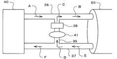
図1において、40は、酸素富化膜等を介して酸素を富化した高圧気体の加圧源となるコンプレッサで、本考案の装置本体50に連結する高圧気体の供給管路36によって、矢標A、Bのように装置本体50内に高圧気体を供給すると共に、装置本体50からは排気管路37を介して矢標E、Fのように装置本体50内の高圧空気を回収して酸素を富化して高圧気体として再度供給管36から装置本体50内に循環して供給するように構成してある。   In FIG. 1, reference numeral 40 denotes a compressor serving as a pressurizing source for high-pressure gas enriched with oxygen through an oxygen-enriched film or the like, and an arrow is provided by a high-pressure gas supply line 36 connected to the apparatus main body 50 of the present invention. The high pressure gas is supplied into the apparatus main body 50 as indicated by marks A and B, and the high pressure air within the apparatus main body 50 is recovered from the apparatus main body 50 via the exhaust pipe 37 as indicated by arrows E and F. Oxygen is enriched and the high-pressure gas is again circulated and supplied from the supply pipe 36 into the apparatus main body 50.

本考案装置は、前記供給管路36と排気管路37との間をエアドライヤ38を具備する除湿管路39で連結し、矢標Dで示すように排気管路37の排気の一部をポンプ41で除湿管路39に取り込んでエアドライヤ38に送り込み除湿させ、矢標Cで示すように除湿した空気を供給管路36に循環供給し、装置本体50内の除湿を行うように構成してある。   In the device according to the present invention, the supply line 36 and the exhaust line 37 are connected by a dehumidifying line 39 having an air dryer 38, and a part of the exhaust gas in the exhaust line 37 is pumped as indicated by an arrow D. 41, the air is taken into the dehumidifying pipe 39 and sent to the air dryer 38 to be dehumidified, and the dehumidified air is circulated and supplied to the supply pipe 36 as indicated by the arrow C to dehumidify the apparatus main body 50. .

上記エアドライヤ38は除湿機能を有すると共に除湿した空気の温度を調整する機能を有し、装置本体50内の湿度と温度に対応して除湿する排気の量と温度を制御する構成にすることが可能である。上記エアドライヤ38本体が除湿すべき空気を吸排気するポンプ機能を内蔵する構成にすることも勿論可能である。   The air dryer 38 has a dehumidifying function and a function of adjusting the temperature of the dehumidified air, and can control the amount and temperature of exhaust to be dehumidified in accordance with the humidity and temperature in the apparatus main body 50. It is. Needless to say, the air dryer 38 may have a built-in pump function for sucking and exhausting air to be dehumidified.

図示の実施例の場合、ポンプ41は、エアドライヤ38に供給する排気の量を調整する機能を有し、ポンプ41を制御することによって除湿する排気の量と除湿空気の温度を調整することができる。   In the case of the illustrated embodiment, the pump 41 has a function of adjusting the amount of exhaust gas supplied to the air dryer 38, and the amount of exhaust gas to be dehumidified and the temperature of the dehumidified air can be adjusted by controlling the pump 41. .

上記本考案に係るエアドライヤ38は、毎分約20〜100リットルの範囲内で排気管路37の排気を除湿して供給管路36に循環供給することができ、装置本体50内の湿度を約20〜60%に除湿することができるように構成してある。また、エアドライヤ38は、除湿後の空気の温度を、例えば、約摂氏15乃至28度の範囲内の所定の温度に調整可能に設けてあり、供給管路36を介して装置本体50内に供給してその温度を、例えば、摂氏15乃至28度の範囲内の所定の温度に調整して、装置内の温度を利用者に快適な湿度と温度に保持することができるように構成してある。   The air dryer 38 according to the present invention can dehumidify exhaust gas in the exhaust line 37 and circulate and supply it to the supply line 36 within a range of about 20 to 100 liters per minute. It is comprised so that it can dehumidify to 20 to 60%. The air dryer 38 is provided so that the temperature of the air after dehumidification can be adjusted to a predetermined temperature within a range of about 15 to 28 degrees Celsius, for example, and is supplied into the apparatus main body 50 via the supply pipe 36. The temperature is adjusted to a predetermined temperature within a range of 15 to 28 degrees Celsius, for example, so that the temperature in the apparatus can be maintained at a humidity and temperature comfortable for the user. .

なお、従来通り、コンプレッサ40により毎分20リットルの排気を酸素富化して毎分20リットルの割合で装置本体50に供給して、外気約摂氏25度のとき装置本体内の温度が摂氏約30度で湿度が約70%であった時に、除湿管路39のエアドライヤ38により毎分約70リットルを約30%に除湿して摂氏約25度で供給管路36に供給するだけで、装置本体50内の温度を摂氏約28度以下で湿度を40%以下に簡単に下げることができた。   In addition, as usual, the exhaust gas of 20 liters per minute is enriched with oxygen by the compressor 40 and supplied to the apparatus main body 50 at a rate of 20 liters per minute. When the outside air is about 25 degrees Celsius, the temperature inside the apparatus main body is about 30 degrees Celsius. When the humidity is about 70% and the air dryer 38 of the dehumidification line 39 dehumidifies about 70 liters per minute to about 30% and supplies it to the supply line 36 at about 25 degrees Celsius, The temperature within 50 could be easily reduced to about 28 degrees Celsius or less and the humidity to 40% or less.

図2に記載の実施例において、1は通気性と折り畳み可能な柔軟性を有すると共に高圧気体の内圧に対して耐圧性を有する上記装置本体50の外側袋体で、帆布、ナイロンの強化繊維を含む織物、網状体等の軽量で引っ張り強度の大きい素材からなり、中に人が横臥して入れる横長胴部2と前後面部3で封鎖した横長筒状体の形状をなしている。   In the embodiment shown in FIG. 2, reference numeral 1 denotes an outer bag body of the apparatus main body 50 having air permeability and foldable flexibility, and having pressure resistance against the internal pressure of high-pressure gas. It is made of a lightweight and high tensile strength material such as a woven fabric or a net-like body, and has a shape of a horizontally long cylindrical body sealed by a horizontally long body portion 2 and a front and back surface portion 3 that a person lies on its side.

横長胴部2の上面には長手方向に耐久性ファスナー5によって開閉する出入口が設けてある。6は出入口の両側に長手方向に設けた布状の補強材である。なお、補強材6は横長胴部2の下面にも対象的に設けてある。   On the upper surface of the horizontally long body portion 2, an entrance that opens and closes by a durable fastener 5 is provided in the longitudinal direction. Reference numeral 6 denotes a cloth-like reinforcing material provided in the longitudinal direction on both sides of the entrance / exit. In addition, the reinforcing material 6 is also provided on the lower surface of the horizontally long body portion 2 in a targeted manner.

また、図では省略したが、横長胴部2の人間が横臥したときに顔の横に位置する側面部に、耐圧性の透明合成樹脂からなる透視窓部を設けてある。   Although not shown in the figure, a see-through window portion made of a pressure-resistant transparent synthetic resin is provided on a side surface portion located on the side of the face when a person lying on the horizontally long body portion 2 lies down.

実施例の場合、前後面部3は前面と後面とが同じ円形状からなると共に、実質的に横長胴部2と同じ素材からなり、図6に記載のように、前後面部3の周縁部と横長胴部2の端部とを引っ張り強度の大きいナイロンの強化繊維等からなる糸状の連結固定部材4によって一体に固定してあり、内圧を受けてほぼ球状に膨らむこととなる。   In the case of the embodiment, the front and rear surface portion 3 has the same circular shape on the front surface and the rear surface, and is substantially made of the same material as that of the horizontally long body portion 2, as shown in FIG. The end portion of the body portion 2 is integrally fixed by a thread-like connecting and fixing member 4 made of nylon reinforcing fiber or the like having a high tensile strength, and is swelled into a substantially spherical shape by receiving internal pressure.

図3において、10は折り畳み可能な柔軟性を有すると共に、微通気性ファスナー13の出入口以外は非通気性を有する上記装置本体50の内側袋体で、実施例の場合、透明又は半透明の薄いビニール樹脂等の合成樹脂材からなり、窓を設けることなく内外から反対側を透視できると共に、軽量で小さく折り畳んで移動することができる。   In FIG. 3, reference numeral 10 denotes an inner bag body of the apparatus main body 50 that has foldable flexibility and is non-breathable except for the entrance / exit of the micro-breathable fastener 13. In the case of the embodiment, the thin bag is transparent or translucent. It is made of a synthetic resin material such as vinyl resin, and can be seen through the opposite side from the inside and outside without providing a window, and it can be folded and moved in a light weight.

内側袋体10は外側袋体1に比較してやや大きめな形状からなり、横長胴部11と前後面部12とは非通気性の同一素材の合成樹脂を熔着して一体に連結してある。また、横長胴部11の上面には外側袋体1とほぼ同じ位置に微通気性ファスナー13で開閉する出入口が設けてある。   The inner bag body 10 has a slightly larger shape than the outer bag body 1, and the laterally long body portion 11 and the front and rear surface portions 12 are integrally connected by welding a non-breathable synthetic resin of the same material. In addition, on the upper surface of the laterally long body portion 11, an entrance that opens and closes with a slightly breathable fastener 13 is provided at substantially the same position as the outer bag body 1.

内側袋体10の出入口に設けた微通気性ファスナー13は、内側袋体10を加圧膨張する際に微流出する気体の流出圧力により膨出して皺や弛みを除去され、外側袋体1に対して形を整えられて密着するから、加圧膨張状態で内側袋体10の一部が弛みや皺がよる状態で外側袋体に密着したとしても、利用者の出入口部分には弛みや皺が生じないから、予想外の収縮や引っ張り応力によって気密性が阻害される恐れがなく、且つ、出入口部分に弛みや皺が生じないから、出入口に設けた微通気性ファスナー13の開き操作が円滑にでき、長期使用によっても耐久性や気密性が維持される効果がある一方、出入口からの内部気体の微流出によって内側袋体から外側袋体に加わる圧力を緩和することができると共に、内側袋体の内部気体の流動と換気ができ、湿気を除去することができる効果がある。   The micro-breathable fastener 13 provided at the entrance / exit of the inner bag body 10 is swelled by the outflow pressure of the gas that slightly flows when the inner bag body 10 is pressurized and expanded to remove wrinkles and slack. Since the shape of the inner bag body 10 is in close contact with the outer bag body in a pressurized and expanded state, even if the inner bag body 10 is in close contact with the outer bag body due to slack or wrinkles, there is a slack or wrinkle at the entrance / exit portion of the user. Therefore, there is no risk of airtightness being hindered by unexpected shrinkage or tensile stress, and no loosening or wrinkling occurs at the entrance / exit, so that the opening operation of the micro-breathable fastener 13 provided at the entrance / exit is smooth. While maintaining the durability and airtightness even after long-term use, the pressure applied from the inner bag body to the outer bag body due to the slight outflow of the internal gas from the inlet / outlet can be relieved, and the inner bag The flow of gas inside the body Care can be, there is an effect that it is possible to remove the moisture.

また、本考案は、前記の高圧気体供給装置において、微通気性ファスナーの微通気性が毎分10リットル乃至120リットルからなる構成を有する。内側袋体の気圧を微通気性ファスナーの微通気性(排気量)に合わせて、大気圧が1.0気圧で酸素濃度が約21%なのに対して、利用者の酸素必要濃度に合わせて、所定に維持すべく、供給する富酸素高圧気体の供給量を供給することによって、種々の通気性ファスナーを採用することができる。   Further, the present invention has a configuration in which the micro-breathable fastener has a micro-breathability of 10 liters to 120 liters per minute in the high-pressure gas supply device. Adjust the air pressure of the inner bag body to the micro-breathability (displacement) of the micro-breathable fastener, while the atmospheric pressure is 1.0 atm and the oxygen concentration is about 21%, whereas according to the user's required oxygen concentration, Various breathable fasteners can be employed by supplying a supply amount of the oxygen-rich high-pressure gas to be supplied in order to maintain the predetermined amount.

また、本考案は、微通気性ファスナーの微通気性を毎分30リットル乃至50リットルからなる構成にすることにより、装置本体を酸素富化装置として富酸素高圧気体を毎分30乃至40リットル供給することで排気調整弁等を頻繁に用いることなく好ましくバランスさせることができる。   Further, according to the present invention, the micro-breathable fastener has a micro-breathability of 30 to 50 liters per minute, so that the main body of the apparatus is an oxygen enricher and 30 to 40 liters of oxygen-rich high-pressure gas is supplied per minute. By doing so, it is possible to preferably balance without frequently using an exhaust adjustment valve or the like.

なお、この場合。排気調整弁は、酸素富化装置として、毎分0乃至200リットルの排気調整ができれば好ましい。   In this case. The exhaust adjustment valve is preferably an oxygen enricher if it can adjust exhaust from 0 to 200 liters per minute.

また、本考案は、前載の高圧気体供給装置において、内側袋体の内部が1.1気圧乃至1.5気圧で酸素濃度が25%乃至50%からなる構成にすることにより、装置本体を酸素富化装置として提供することができる。   Further, according to the present invention, in the above-described high-pressure gas supply device, the inside of the inner bag body is configured to have a pressure of 1.1 to 1.5 atmospheres and an oxygen concentration of 25 to 50%. It can be provided as an oxygen enrichment device.

また、前記高圧気体供給装置は、成人の大人用であれば、横幅及び高さが約80cm乃至100cm等、長さが190cm乃至220cm等に設定でき、子供用或いは犬等用であれば、横幅及び高さが約60cm乃至100cm等、長さが100cm乃至180cm等に設定でき、また、幼児用或いは猫等用であれば、横幅及び高さが約40cm乃至100cm等、長さが50cm乃至120cm等に設定できる。   The high-pressure gas supply device can be set to have a width and height of about 80 cm to 100 cm, a length of 190 cm to 220 cm, etc. for adults, and a width of 190 cm to 220 cm for children or dogs. The height can be set to about 60 cm to 100 cm, the length can be set to 100 cm to 180 cm, and the width and height can be set to about 40 cm to 100 cm, and the length can be set to 50 cm to 120 cm. Etc. can be set.

図8又は図9に記載の実施例の場合、内側袋体10の内部には、横長胴部2の両端部に位置して内接する中空リング体30を設けると共に、前記中空リング体30の間に中空敷物体31を一体に収容してある。中空リング体30及び中空敷物体31は、それぞれ手動又は電動の空気ポンプで膨らませることができ、内側袋体10内に中空リング体30と中空敷物体31を収容して膨らませることによって、横長筒状体からなる装置本体50を出入口を開いた状態で組み立て状態に維持することができる。また、出入口を開いた状態で維持することができるから、利用者が内及び外側の袋体1,10からかなる装置本体内に自由に出入りすることができると共に、一端部を頭位置にして楽に横臥することができる。   In the case of the embodiment shown in FIG. 8 or FIG. 9, inside the inner bag body 10, there are provided hollow ring bodies 30 positioned at both ends of the laterally long body portion 2 and inscribed, and between the hollow ring bodies 30. The hollow covering object 31 is accommodated integrally. The hollow ring body 30 and the hollow covering object 31 can be inflated manually or by an electric air pump, respectively, and the hollow ring body 30 and the hollow covering object 31 are accommodated in the inner bag body 10 and inflated. The apparatus main body 50 made of a cylindrical body can be maintained in the assembled state with the doorway opened. In addition, since the doorway can be maintained in an open state, the user can freely go into and out of the apparatus body consisting of the inner and outer bag bodies 1 and 10, and the one end portion can be in the head position. You can lie down comfortably.

図10に記載の実施例において、外側袋体1の耐久性ファスナー5の両側には、補強材6と平行して長手方向に棒状の出入口支持枠体28を設けあり、前記中空リング体30と中空敷物体31を収容して膨らませることによって成形した横長筒状体の装置本体50において、出入口を開いた状態で出入口支持枠体28によって外側袋体1の出入口を確実に支持することができるから、利用者が袋体内に楽に横臥することができると共に、出入口から自由に出入りすることができる。   In the embodiment shown in FIG. 10, on both sides of the durable fastener 5 of the outer bag body 1, bar-shaped entrance / exit support frame bodies 28 are provided in the longitudinal direction in parallel with the reinforcing material 6, and the hollow ring body 30 In the apparatus body 50 of a horizontally long cylindrical body formed by accommodating and inflating the hollow covering object 31, the entrance / exit of the outer bag body 1 can be reliably supported by the entrance / exit support frame body 28 with the entrance / exit opened. Therefore, the user can lie down comfortably in the bag body and can freely enter and exit from the entrance.

出入口支持枠体28は、外側袋体1に一体に取り付けた柔軟な中空取付枠内に中空な棒状体を差し込んで簡単に構成することができると共に、パイプ状の棒状体は伸縮自在な釣り竿又は折り畳み式の杖等のような伸縮構造を備えることが携帯、運搬する上で好ましい。   The entrance / exit support frame 28 can be simply configured by inserting a hollow rod-like body into a flexible hollow attachment frame integrally attached to the outer bag body 1, and the pipe-like rod-like body is a telescopic fishing rod or It is preferable to provide a telescopic structure such as a foldable cane for carrying and carrying.

図11又は図12に記載の実施例の場合、内側袋体10と外側袋体1とに、互いに着脱可能に固定する着脱部材32,33を設けてあり、組み立て時や空気排出後に内外の袋体1,10を互いに着脱可能に固定して、主として互いの出入口がずれないように構成してある。従って、着脱部材32,33は内側袋体10と外側袋体1の出入口の付近に配設することが好ましく、互いの出入口がずれないように合致させることができる。   In the case of the embodiment shown in FIG. 11 or FIG. 12, the inner bag body 10 and the outer bag body 1 are provided with detachable members 32 and 33 that are detachably fixed to each other. The bodies 1 and 10 are detachably fixed to each other so that their doorways are not displaced. Therefore, the detachable members 32 and 33 are preferably disposed in the vicinity of the entrance / exit of the inner bag body 10 and the outer bag body 1 and can be matched so that the entrance / exit of each other does not shift.

また、着脱部材32,33はボタンやフックにより定点的に互いに着脱する構成にすることもできるが、互いに着脱自在に掛合する多数のフックとループを備えた面ファスナーからなる構成にすることにより、着脱面をずらせて着脱することができるから着脱部材の面積の大小と配置と着脱操作を容易にする効果がある。   In addition, the detachable members 32 and 33 can be configured to be detachably attached to each other by a button or a hook, but by configuring the hook and loop with a number of hooks and loops that are detachably engaged with each other, Since the attachment / detachment surface can be shifted and attached, there is an effect of facilitating the arrangement and attachment / detachment operations of the attachment / detachment member.

なお、図11において、34は内側袋体1の微通気性ファスナー13を予め一体に固着したファスナー取付袋部分で、個別に製作した内側袋体10の横長胴部11の部分と一体に接着又は溶着して設けてある。   In FIG. 11, reference numeral 34 denotes a fastener-attaching bag portion to which the micro-breathable fastener 13 of the inner bag body 1 is fixed in advance, and is bonded or integrated with the horizontally elongated body portion 11 of the individually manufactured inner bag body 10. It is provided by welding.

ファスナー取付袋部分34は、他の内側袋体10の横長胴部11の部分より大きい伸張弾力性を有する構成にして、内側袋体1を加圧膨張するときに微通気性ファスナー13に長手方向に直線的に伸張しやすい伸張弾力性を付与することができる。ファスナー取付袋部分34の伸張弾力性を付与する手段としては、ファスナー取付袋部分34を弾力性の比較的大きい素材から製作する手段、同じ素材で他の袋部分より肉厚の大きい材料を使用して製作する手段を挙げることができる。   The zipper attachment bag portion 34 is configured to have a greater elasticity than the portion of the laterally long body portion 11 of the other inner bag body 10, and the longitudinal direction of the slightly breathable fastener 13 when the inner bag body 1 is pressurized and expanded. It is possible to provide stretch elasticity that is easy to stretch linearly. As means for imparting the stretch elasticity of the fastener attaching bag portion 34, means for manufacturing the fastener attaching bag portion 34 from a material having a relatively large elasticity, and using the same material and a material thicker than other bag portions are used. Can be mentioned.

図11の実施例の場合、そのファスナー取付袋部分34上に面ファスナー32を接着して設けてある。図では配置を省略したが、図11に記載のように、面ファスナー32に相対する外側袋体1の内側に面ファスナー33が配設してある。   In the case of the embodiment of FIG. 11, the hook-and-loop fastener 32 is bonded on the fastener-attaching bag portion 34. Although not shown in the drawing, a hook-and-loop fastener 33 is disposed on the inner side of the outer bag body 1 facing the hook-and-loop fastener 32 as shown in FIG.

また、図9,10又は12に記載のように、装置本体50の外側袋体1の横長胴部2の外側の両側に位置して、長手方向に支持中空体35を設けてあり、横長筒状体からなる装置本体50を横転しないように支持中空体35によって支持することができるように構成してある。   Moreover, as shown in FIG. 9, 10 or 12, it is located in the both sides of the outer side body part 2 of the outer side bag body 1 of the apparatus main body 50, and the support hollow body 35 is provided in the longitudinal direction, and a horizontal cylinder The device main body 50 made of a solid body is configured to be supported by the support hollow body 35 so as not to roll over.

実施例の場合、支持中空体35は柔軟な膨張及び折り畳み可能な円柱状の袋体からなり、図12に記載のように、外側袋体1に面ファスナー等によって直接に一体に取り付けることもできるが、左右の支持中空体35を平行に連結帯で連結する構成にすることによって、図8に記載のように、支持中空体35の間の前記連結帯の上に横長筒状体からなる装置本体50を載置することによって、支持中空体35を装置本体50の両側に容易に安定して設置することができる。   In the case of the embodiment, the support hollow body 35 is formed of a flexible cylindrical bag body that can be expanded and folded, and can be directly attached to the outer bag body 1 with a hook-and-loop fastener or the like as shown in FIG. However, by configuring the left and right support hollow bodies 35 to be connected in parallel by a connection band, as shown in FIG. 8, a device comprising a horizontally long cylindrical body on the connection band between the support hollow bodies 35. By mounting the main body 50, the support hollow body 35 can be easily and stably installed on both sides of the apparatus main body 50.

また、本考案は、図2、3に記載のように、内側袋体10の一前後面部12と外側袋体1の一前後面部3には、組み立て時にほぼ一致する位置に任意個数の貫通孔14、7が設けてある。また、貫通孔14、7の周囲には密着して高い気密性が得られる合成樹脂膜等からなる補強枠材15を一体に設け、貫通孔14,7に強度的な厚みを付与する共に、同時に締め付け時にパッキング効果を付与するように構成してある。   In addition, as shown in FIGS. 2 and 3, in the present invention, an arbitrary number of through-holes are formed in the front and rear surface portions 12 of the inner bag body 10 and the front and rear surface portions 3 of the outer bag body 1 at substantially the same positions during assembly. 14 and 7 are provided. In addition, a reinforcing frame member 15 made of a synthetic resin film or the like that is in close contact with the periphery of the through holes 14 and 7 to obtain high airtightness is integrally provided, and the through holes 14 and 7 are provided with a strong thickness, At the same time, a packing effect is provided when tightening.

また、図6、7に記載のように、柔軟な外側袋体1のファスナー5を開いて、柔軟な内側袋体10をその中に収容し、前記貫通孔14,7を合致させ、パイプ状の連結部材20を嵌合することによって内外の袋体10,1を組み立て可能に設け、連結部材20によって加圧源からの高圧気体を供給するように構成してあり、内側袋体1と外側袋体10とを貫通孔14、7に嵌合するパイプ状の連結部材20によって内外の袋体を組み立てることができると共に、連結部材20によって加圧源からの高圧気体を内側袋体10内に供給して一体に装置を膨張することができる。   Also, as shown in FIGS. 6 and 7, the fastener 5 of the flexible outer bag 1 is opened, the flexible inner bag 10 is accommodated therein, the through holes 14, 7 are matched, The inner and outer bag bodies 10, 1 are provided so as to be assembled by fitting the connecting members 20, and the connecting member 20 is configured to supply a high-pressure gas from a pressure source. Inner and outer bag bodies can be assembled by the pipe-shaped connecting member 20 that fits the bag body 10 into the through holes 14 and 7, and the connecting member 20 allows high-pressure gas from a pressurizing source to enter the inner bag body 10. The device can be inflated as a single unit.

また、連結部材20は、図6又は図7に記載のごとく、中央に雌ネジ付きの連結孔22を有する連結ボルト部21の頭部を内側袋体10の内側にしてボルトネジ部23を貫通孔14、7に通し、次いで、外側袋体1の外側からパッキング24を介して連結ナット部25をボルトネジ部23にねじ込み、強固に締め付けて連結部材20を貫通孔14、7に固定し、連結孔22の雌ネジ部にパイプ状の接続管部材26の雄ネジ部27を気密を維持するまで螺合して、貫通孔14、7への取り付けが完了する。   Further, as shown in FIG. 6 or FIG. 7, the connecting member 20 has the connecting bolt portion 21 having a connecting hole 22 with a female screw at the center as the inner side of the inner bag body 10 and the bolt screw portion 23 as a through hole. 14, 7, and then the connection nut portion 25 is screwed into the bolt screw portion 23 from the outside of the outer bag body 1 through the packing 24, and is firmly tightened to fix the connection member 20 to the through holes 14, 7. The male threaded portion 27 of the pipe-shaped connecting pipe member 26 is screwed into the female threaded portion 22 until the airtightness is maintained, and the attachment to the through holes 14 and 7 is completed.

この作業を、実施例では4個所で行うことによって、内側袋体10と外側袋体1とを連結して組み立て、接続管部材26に、図では省略した加圧源からの高圧気体の充填用パイプ、充填後の空気循環補助用の排気パイプ、装置内の酸素濃度、気圧、温度、湿度等の検出装置、使用後排気用パイプを取り付けて、本考案装置の使用準備は完了する。   In this embodiment, this operation is performed at four locations to connect and assemble the inner bag body 10 and the outer bag body 1, and the connection pipe member 26 is filled with high-pressure gas from a pressurization source omitted in the figure. The pipe, the exhaust pipe for assisting air circulation after filling, the detection device for oxygen concentration, atmospheric pressure, temperature, humidity and the like in the apparatus, and the exhaust pipe after use are attached, and the preparation for use of the device of the present invention is completed.

内側袋体10内に利用者が寝そべることができる敷物や頭部を保護する枕等を収容し、利用者が横臥した状態で内側の微通気性ファスナー13を閉じ、空気より酸素濃度のやや濃い高圧気体の充填を開始し、内側袋体10が、図4に記載の状態を経てある程度の形をなす大きさに膨らんだところで外側袋体1の耐圧性ファスナー5を閉じて、図5に記載のように、内側袋体1内の気圧が周囲の大気圧より高い所定の圧力に達するまで膨張させると、内側袋体10の加圧膨張によって微通気性ファスナー13からなるの利用者の出入口部分は、微流出する気体の流出圧力によって膨出する方向に沿って形を整えられて外側袋体5に密着し、高圧気体の充填の継続により加圧膨張状態で所定の圧力で外側袋体1に安定して密着することとなる。   A rug that can be laid down by the user, a pillow that protects the head, and the like are accommodated in the inner bag body 10, and the inner micro-breathable fastener 13 is closed while the user is lying down, so that the oxygen concentration is slightly higher than the air. The filling of the high-pressure gas is started, and the pressure-resistant fastener 5 of the outer bag body 1 is closed when the inner bag body 10 is inflated to a certain size through the state shown in FIG. When the air pressure in the inner bag body 1 is inflated until it reaches a predetermined pressure higher than the surrounding atmospheric pressure, the inlet / outlet portion of the user comprising the micro-breathable fastener 13 by the pressure expansion of the inner bag body 10 Is shaped along the direction of expansion by the outflow pressure of the gas that slightly flows out, closely contacts the outer bag 5, and the outer bag 1 at a predetermined pressure in a pressurized and expanded state by continuing the filling of the high-pressure gas. Will adhere stably.

従って、微通気性ファスナー13に予測を超える収縮や引っ張り応力が加わって変形した状態で外側袋体1に密着するようなことがないと共に、内側袋体10から外側袋体1に不用意な高圧力が作用することを緩和することができることとなる。   Accordingly, the micro-breathable fastener 13 is not in close contact with the outer bag body 1 in a deformed state due to excessive shrinkage or tensile stress applied to the micro-breathable fastener 13, and an inadvertent height from the inner bag body 10 to the outer bag body 1. It is possible to alleviate the action of pressure.

また、出入口部分に弛みや皺が生じないから、出入口に設けた微通気性ファスナー13の開き操作が円滑にでき、長期使用によっても耐久性や気密性が維持される一方、仰向けに横臥した利用者の顔の上方の微通気性ファスナー13からの内部気体が微流出するから、内側袋体10の内部気体の流動と換気が利用者の顔の上方で快適にできることとなる。   In addition, since there is no slack or wrinkle at the entrance / exit, the opening operation of the micro-breathable fastener 13 provided at the entrance / exit can be smoothly performed, and durability and airtightness are maintained even after long-term use, while the use is lying on its back Since the internal gas from the slightly breathable fastener 13 above the person's face slightly flows out, the flow and ventilation of the internal gas in the inner bag 10 can be comfortably performed above the user's face.

一定の高圧気体の供給は、微通気性ファスナー13から気体が噴出を開始した後、利用者の様子を観察しながら、また、希望を聞きながら、所定時間経過するまで、所定の酸素濃度と気圧、温度、湿度を制御しながら継続されることとなる。   The constant high-pressure gas is supplied after the gas starts to be ejected from the micro-breathable fastener 13, while observing the state of the user and listening for hope until a predetermined time elapses. It will be continued while controlling the temperature and humidity.

なお、通常の場合、人体は1気圧の酸素濃度21%の大気から肺でガス交換をし、体内では炭酸ガスと交換した酸素を赤血球により細胞に運び酸素濃度の低い細胞とガス交換して肺に戻り、気圧が上がれば取り込む酸素濃度も上がり、酸素濃度60%以上になると酸素中毒を起こすと言われているから、本願装置の供給気体の酸素濃度は、体に負担をかけない大気の酸素濃度21%以上40%未満で、30〜35%が好ましく、高圧時の気圧は1.2気圧から1.3気圧で、好ましくは1.22気圧乃至1.25気圧が好ましい。   In a normal case, the human body exchanges gas from the atmosphere with an oxygen concentration of 21% at 1 atm, and in the body, oxygen exchanged with carbon dioxide is carried to cells by red blood cells and gas exchange with cells with low oxygen concentration. It is said that if the atmospheric pressure increases, the oxygen concentration to be taken in increases, and it is said that oxygen poisoning occurs when the oxygen concentration exceeds 60%. Therefore, the oxygen concentration of the supply gas of the device of the present application is atmospheric oxygen that does not impose a burden on the body. The concentration is 21% or more and less than 40%, preferably 30 to 35%, and the atmospheric pressure at high pressure is 1.2 to 1.3 atm, preferably 1.22 to 1.25 atm.

図5の装置本体の加圧膨張状態において、内側袋体10はその微通気性を越えて充填される気体を密封して膨張状態に向かって膨らもうとする状態にあるが、通気性があり耐圧性の外側袋体1は、図4で示す内外袋体の中間に存在する空気8を間に閉じ込めることなく外側袋体1から外気に自由に放出し、内側袋体10の膨張力に抗して横長円筒形状を維持し、前後面部3が球形状に膨らむ程度で、内側袋体10を内側に密着した状態で押し込め、装置外形を維持することとなる。   In the pressurized and expanded state of the apparatus main body of FIG. 5, the inner bag body 10 is in a state of sealing the gas filled beyond its fine air permeability and inflating toward the expanded state. The outer pressure-resistant outer bag body 1 freely releases the air 8 existing in the middle of the inner and outer bag bodies shown in FIG. In contrast, the laterally long cylindrical shape is maintained, and the inner bag body 10 is pushed in in a state of being in close contact with the inside so that the front and rear surface portions 3 swell into a spherical shape, thereby maintaining the outer shape of the apparatus.

従って、内側袋体10は、内圧を受けて膨張した状態で外側袋体1より大きくなる膨張性を備えればよいから、単に内圧を受けない状態で外側袋体1より大きい条件を満たす場合だけではなく、内圧を受けない状態では外側袋体1より容量は小さいが、内圧を受けて膨張した状態では外側袋体1より大きくなる伸縮性又は伸展性を有する袋体であってもよいことになる。   Therefore, the inner bag body 10 only needs to have an expandability that is greater than that of the outer bag body 1 in a state where the inner bag body is expanded by receiving an internal pressure. However, the capacity may be smaller than that of the outer bag body 1 in a state where the inner pressure is not received, but may be a bag body having stretchability or extensibility that is larger than that of the outer bag body 1 in a state where the inner bag is inflated. Become.

そして、この場合も、内側袋体10は膨張の途中の状態で外側袋体1に密着して膨張を止めた状態であるから、内側袋体のファスナー13は周囲の袋体部分から強い引っ張り力を受けない状態に維持されることとなる。   Also in this case, since the inner bag 10 is in a state of being in close contact with the outer bag 1 in the middle of expansion, the inner bag body 10 is in a state where the expansion is stopped. It will be maintained in the state which does not receive.

外側袋体1の耐圧性ファスナー5は内側袋体1の膨張力を保持する耐圧性を必要とし、内側袋体10の微通気性ファスナー13は、供給される外気より高い所定圧力に空気を閉じ込めた状態に維持する所定の非通気性を必要とする。この供給される高圧気体との関係で通気し、内側袋体10内を所定の圧力に維持することができる微通気性ファスナーを本考案では微通気性ファスナーと称する。   The pressure-resistant fastener 5 of the outer bag body 1 needs pressure resistance to maintain the expansion force of the inner bag body 1, and the slightly breathable fastener 13 of the inner bag body 10 traps air at a predetermined pressure higher than the supplied outside air. It must have a certain air permeability that is maintained in the normal state. The finely breathable fastener that can ventilate in relation to the supplied high-pressure gas and can maintain the inside bag body 10 at a predetermined pressure is referred to as a finely breathable fastener in the present invention.

また、外側袋体1の耐圧性ファスナー5は、外側袋体1が通気性を有することにより、従来の袋体が非通気性の場合に比較して、内側袋体10との間の空気8を排出するための通気性を必須の条件としないから、通気性に関して自由な構成のファスナーを採用することができる。   In addition, the pressure-resistant fastener 5 of the outer bag body 1 has the air 8 between the inner bag body 10 and the outer bag body 1 as compared with the case where the conventional bag body is non-breathable because the outer bag body 1 is breathable. Since the air permeability for discharging the air is not an indispensable condition, it is possible to employ a fastener having a free configuration with respect to the air permeability.

即ち、外側袋体1のファスナー5は通気性があってもなくても所定の耐圧性があればよいのに対して、内側袋体10のファスナー13は所定の耐圧性は必要であるが微通気性によって自らの耐圧性を緩和することができる。   In other words, the fastener 5 of the outer bag body 1 only needs to have a predetermined pressure resistance regardless of whether or not it has air permeability, whereas the fastener 13 of the inner bag body 10 needs a predetermined pressure resistance, but is fine. The pressure resistance can be relaxed by the air permeability.

そして、内側袋体10の微通気性ファスナー13がファスナー全体に渡ってほぼ均等な微通気性を有することより、微通気性によるファスナー全体の耐圧性を緩和することができると共に、均等な微通気性により排気音を微弱にして、ファスナー両端部や隙間からの集中的な排気音による不快感を緩和することができる。   And since the slightly breathable fastener 13 of the inner bag body 10 has substantially uniform breathability over the entire fastener, the pressure resistance of the entire fastener due to the minute breathability can be eased and the uniform breathable The exhaust sound can be weakened by the nature, and the discomfort caused by the concentrated exhaust sound from both ends of the fastener and the gap can be alleviated.

また、この場合、加圧機構の加圧源から高圧気体を微通気性ファスナー13の通気性を補って供給することより、高圧気体状態を維持しながら微通気ファスナー13によって内部空気の換気をすることができる。   In this case, the high-pressure gas is supplied from the pressurizing source of the pressurizing mechanism while supplementing the air permeability of the micro-breathable fastener 13 so that the internal air is ventilated by the micro-breathable fastener 13 while maintaining the high-pressure gas state. be able to.

また、本考案は、外側袋体1のファスナー5と内側袋体10のファスナー13とが直接に接しないように設けてあることより、互いにファスナーの開閉を阻害しないように構成してある。9,16はそれぞれファスナー5,13のスライダ取っ手である。   In addition, the present invention is configured so that the fastener 5 of the outer bag body 1 and the fastener 13 of the inner bag body 10 are not in direct contact with each other so that the opening and closing of the fasteners is not hindered. Reference numerals 9 and 16 denote slider handles for the fasteners 5 and 13, respectively.

この場合、外側袋体1のファスナー5と内側袋体10のファスナー13との配設位置をお互いが重なり合わない位置に外して設けることもできるが、実施例の場合、図4又は図5に記載のように、外側袋体1と内側袋体10のファスナー5,13の間に、長手方向に沿って、隔膜体17を設けてある。隔膜体17は外側袋体1のファスナー5の下側に沿って長手方向にファスナー5の両側から2重に延設してあり、それぞれ相対するファスナー5,13に相対するように設けてある。   In this case, the arrangement positions of the fasteners 5 of the outer bag body 1 and the fasteners 13 of the inner bag body 10 can be removed at positions where they do not overlap each other. As described, the diaphragm body 17 is provided between the outer bag body 1 and the fasteners 5 and 13 of the inner bag body 10 along the longitudinal direction. The diaphragm body 17 is doubled from both sides of the fastener 5 in the longitudinal direction along the lower side of the fastener 5 of the outer bag body 1, and is provided so as to face the opposite fasteners 5 and 13.

また、この実施例の場合、隔膜体17は非通気性の膜体からなり、内側袋体10の微通気性ファスナー13が非通気性の膜体を介して外側袋体1に密着し、加圧膨張時の非通気性を増強することができるように構成してある。   Further, in this embodiment, the diaphragm body 17 is made of a non-breathable film body, and the micro-breathable fastener 13 of the inner bag body 10 is in close contact with the outer bag body 1 through the non-breathable film body. The non-breathability at the time of pressure expansion can be enhanced.

なお、隔膜体17はファスナー13の上側に内側袋体10に設けることも可能であり、この場合、ファスナー13のスライダ取っ手16を隔膜体17が覆って外側から操作しにくくなるから、スライダ取っ手16を内側袋体10の内側に突出させて設け、中から利用者が開けることができるようにすることができる。   The diaphragm body 17 can also be provided on the inner bag body 10 on the upper side of the fastener 13. In this case, the slider handle 16 of the fastener 13 is covered with the diaphragm body 17, making it difficult to operate from the outside. Can be made to project inside the inner bag body 10 so that the user can open it.

しかし、ファスナー5,13の配設位置をお互いが重なり合わない位置に外して設ける場合には、微通気性ファスナー13に隔膜体17を設ける必要はない。   However, in the case where the fasteners 5 and 13 are provided at positions where the fasteners 5 and 13 are not overlapped with each other, it is not necessary to provide the diaphragm body 17 on the slightly breathable fastener 13.

本考案装置の一実施例の要部を示す概略説明図。The schematic explanatory drawing which shows the principal part of one Example of this invention apparatus. その一実施例の要部を示す概略斜視図。The schematic perspective view which shows the principal part of the one Example. その一実施例の他の要部を示す概略斜視図。The schematic perspective view which shows the other principal part of the one Example. 図2の実施例の要部の一使用態様を縦断して示す概略縦断面図。FIG. 3 is a schematic longitudinal cross-sectional view showing one usage mode of a main part of the embodiment of FIG. 図2の実施例の要部の他の使用態様を縦断して示す概略縦断面図。The schematic longitudinal cross-sectional view which shows the other usage condition of the principal part of the Example of FIG. 2 longitudinally. 図2の実施例の一部の断面を示す概略断面図。FIG. 3 is a schematic cross-sectional view showing a partial cross section of the embodiment of FIG. 2. その一部を取り出して分解して示す概略分解斜視図。FIG. 3 is a schematic exploded perspective view showing a part extracted and disassembled. 本考案装置の一実施例の他の要部を示す概略斜視図。The schematic perspective view which shows the other principal part of one Example of this invention apparatus. 図8の実施例の要部の一使用態様を縦断して示す概略縦断面図。The schematic longitudinal cross-sectional view which shows one usage aspect of the principal part of the Example of FIG. 8 longitudinally. その一実施例の他の要部を示す概略斜視図。The schematic perspective view which shows the other principal part of the one Example. その他の実施例の要部を示す概略斜視図。The schematic perspective view which shows the principal part of another Example. 図11の実施例の要部の一使用態様を縦断して示す概略縦断面図。FIG. 12 is a schematic vertical cross-sectional view showing one usage mode of a main part of the embodiment of FIG.

符号の説明Explanation of symbols

1 外側袋体
2 横長胴部
3 前後面部
4 連結固定部材
5 ファスナー
6 補強材
7 貫通孔
8 空間
9 スライダ取っ手
10 内側袋体
11 横長胴部
12 前後面部
13 微通気性ファスナー
14 貫通孔
15 補強枠材
16 スライダ取っ手
17 隔膜体
20 連結部材
21 連結ボルト部
22 連結孔
23 ボルトネジ部
24 パッキング
25 連結ナット部
26 接続管部材
27 雄ネジ部
28 出入口支持枠体
30 中空リング体
31 中空敷物体
32 着脱部材
33 着脱部材
34 ファスナー取付袋部分
35 支持中空体
36 供給管路
37 排気管路
38 エアドライヤ
39 除湿管路
40 コンプレッサ
41 ポンプ
50 装置本体
DESCRIPTION OF SYMBOLS 1 Outer bag body 2 Horizontally long trunk | drum 3 Front-and-rear surface part 4 Connection fixing member 5 Fastener 6 Reinforcement material 7 Through-hole 8 Space 9 Slider handle 10 Inner bag body 11 Horizontally long trunk | drum 12 Front-and-back surface part 13 Slightly breathable fastener 14 Through-hole 15 Reinforcement frame Material 16 Slider handle 17 Diaphragm body 20 Connecting member 21 Connecting bolt part 22 Connecting hole 23 Bolt screw part 24 Packing 25 Connecting nut part 26 Connecting pipe member 27 Male thread part 28 Entrance / exit support frame 30 Hollow ring body 31 Hollow covering object 32 Detachable member 33 Detachable member 34 Fastener mounting bag portion 35 Support hollow body 36 Supply pipeline 37 Exhaust pipeline 38 Air dryer 39 Dehumidification pipeline 40 Compressor 41 Pump 50 Device body

Claims (16)

高圧気体供給装置において、装置本体内に加圧源から酸素を富化した高圧気体を送り込む供給管路と装置本体内からの排気を加圧源に循環する排気管路とを有する加圧機構を設けると共に、供給管路と排気管路とをエアドライヤを具備する除湿管路で連結し、排気管路の排気を除湿して供給管路に循環供給し装置本体内の除湿を行うようにした高圧気体供給装置。 In the high-pressure gas supply device, a pressurizing mechanism having a supply pipe that feeds oxygen-enriched high-pressure gas from a pressurization source into the apparatus body and an exhaust pipe that circulates exhaust from the apparatus body to the pressurization source High pressure that connects the supply line and the exhaust line with a dehumidification line equipped with an air dryer, dehumidifies the exhaust from the exhaust line, and circulates and supplies the exhaust to the supply line. Gas supply device. 請求項1に記載の高圧気体供給装置において、エアドライヤの除湿後の空気の温度を所定の温度に調整可能に設けてなる高圧気体供給装置。 The high-pressure gas supply apparatus according to claim 1, wherein the air temperature after dehumidification of the air dryer is provided so as to be adjustable to a predetermined temperature. 請求項2に記載の高圧気体供給装置において、エアドライヤの除湿後の空気の温度を所定の温度範囲に制御可能に設けてなる高圧気体供給装置。 The high-pressure gas supply apparatus according to claim 2, wherein the temperature of the air after dehumidification of the air dryer is provided so as to be controlled within a predetermined temperature range. 請求項2又は3に記載の高圧気体供給装置において、所定の温度が摂氏15乃至28度の範囲内の温度からなる高圧気体供給装置。 4. The high pressure gas supply apparatus according to claim 2, wherein the predetermined temperature is a temperature within a range of 15 to 28 degrees Celsius. 請求項1乃至4のいずれかに記載の高圧気体供給装置において、エアドライヤが毎分20〜100リットルの排気管路の排気を除湿して供給管路に循環供給するようにした高圧気体供給装置。 5. The high-pressure gas supply apparatus according to claim 1, wherein an air dryer dehumidifies exhaust gas from an exhaust line of 20 to 100 liters per minute and circulates and supplies the exhaust line to the supply line. 請求項1乃至5のいずれかに記載の高圧気体供給装置において、エアドライヤが装置本体内の湿度を20〜60%に除湿するようにした高圧気体供給装置。 6. The high pressure gas supply apparatus according to claim 1, wherein the air dryer dehumidifies the humidity in the apparatus main body to 20 to 60%. 請求項1乃至6のいずれかに記載の高圧気体供給装置において、排気管路からエアドライヤに排気を送るポンプを設けてなる高圧気体供給装置。 7. The high pressure gas supply apparatus according to claim 1, further comprising a pump for sending exhaust gas from an exhaust pipe line to an air dryer. 請求項7に記載の高圧気体供給装置において、ポンプ内を流れる排気の量を調節してエアドライヤによる除湿又は温度を調整可能に設けてなる高圧気体供給装置。 8. The high pressure gas supply apparatus according to claim 7, wherein the amount of exhaust gas flowing through the pump is adjusted so that dehumidification by an air dryer or temperature can be adjusted. 請求項1乃至8のいずれかに記載の高圧気体供給装置において、装置本体が、折り畳み可能な柔軟性を有する内側袋体と、通気性を有する耐圧性の外側袋体とからなり、内側袋体の出入口が高圧気体に対して全長に渡って微通気性を有する高圧気体供給装置。 The high-pressure gas supply device according to any one of claims 1 to 8, wherein the device main body includes a foldable inner bag body and a breathable pressure-resistant outer bag body, and the inner bag body. The high-pressure gas supply apparatus in which the inlet / outlet of the gas has micro-air permeability over the entire length with respect to the high-pressure gas. 請求項9に記載の高圧気体供給装置において、内側袋体の出入口に微通気性を有する微通気性ファスナーを設けてなる高圧気体供給装置。 The high-pressure gas supply apparatus according to claim 9, wherein a micro-breathable fastener having a micro-breathability is provided at an entrance / exit of the inner bag body. 請求項10に記載の高圧気体供給装置において、微通気性ファスナーがファスナー全体に渡ってほぼ均等な通気性を有する高圧気体供給装置。 The high-pressure gas supply apparatus according to claim 10, wherein the micro-breathable fastener has substantially uniform breathability over the entire fastener. 請求項10又は11に記載の高圧気体供給装置において、微通気性ファスナーの微通気性が毎分10リットル乃至120リットルからなる高圧気体供給装置。 12. The high-pressure gas supply device according to claim 10 or 11, wherein the micro-breathable fastener has a micro-breathability of 10 to 120 liters per minute. 請求項12に記載の高圧気体供給装置において、微通気性ファスナーの微通気性が毎分30リットル乃至50リットルからなる高圧気体供給装置。 The high-pressure gas supply apparatus according to claim 12, wherein the micro-breathable fastener has a micro-breathability of 30 to 50 liters per minute. 請求項10乃至13のいずれかに記載の高圧気体供給装置において、微通気性ファスナーの周囲に伸張弾力性を有するファスナー取付袋部分を設けてなる高圧気体供給装置。 The high-pressure gas supply apparatus according to any one of claims 10 to 13, wherein a fastener mounting bag portion having stretch elasticity is provided around a slightly breathable fastener. 請求項10乃至14のいずれかに記載の高圧気体供給装置において、加圧機構の加圧源から高圧気体を微通気性ファスナーの通気性を補って供給してなる高圧気体供給装置。 The high-pressure gas supply apparatus according to any one of claims 10 to 14, wherein a high-pressure gas is supplied from a pressurization source of a pressurization mechanism while supplementing the air permeability of the micro-breathable fastener. 請求項1乃至15のいずれかに記載の高圧気体供給装置において、装置本体の内部が1.1気圧乃至1.5気圧で酸素濃度が25%乃至50%になることからなる高圧気体供給装置。 The high-pressure gas supply apparatus according to any one of claims 1 to 15, wherein the inside of the apparatus body is 1.1 atm to 1.5 atm and the oxygen concentration is 25% to 50%.
JP2008005743U 2008-08-19 2008-08-19 High pressure gas supply device Expired - Fee Related JP3145976U (en)

Priority Applications (1)

Application Number Priority Date Filing Date Title
JP2008005743U JP3145976U (en) 2008-08-19 2008-08-19 High pressure gas supply device

Applications Claiming Priority (1)

Application Number Priority Date Filing Date Title
JP2008005743U JP3145976U (en) 2008-08-19 2008-08-19 High pressure gas supply device

Publications (1)

Publication Number Publication Date
JP3145976U true JP3145976U (en) 2008-10-30

Family

ID=43295715

Family Applications (1)

Application Number Title Priority Date Filing Date
JP2008005743U Expired - Fee Related JP3145976U (en) 2008-08-19 2008-08-19 High pressure gas supply device

Country Status (1)

Country Link
JP (1) JP3145976U (en)

Cited By (2)

* Cited by examiner, † Cited by third party
Publication number Priority date Publication date Assignee Title
KR20180026617A (en) * 2016-09-02 2018-03-13 (주)아이벡스메디칼시스템즈 High pressure oxygen chamber managing system
WO2022234773A1 (en) * 2021-05-06 2022-11-10 重一 中津川 Shelter

Cited By (2)

* Cited by examiner, † Cited by third party
Publication number Priority date Publication date Assignee Title
KR20180026617A (en) * 2016-09-02 2018-03-13 (주)아이벡스메디칼시스템즈 High pressure oxygen chamber managing system
WO2022234773A1 (en) * 2021-05-06 2022-11-10 重一 中津川 Shelter

Similar Documents

Publication Publication Date Title
US7481220B2 (en) Breathing mask with breathing gas supply through the strap
CN101541289B (en) Hyperbaric Oxygen/Hyperbaric Oxygen Chamber System
CN105854138B (en) Patient interface and mask
CN103252008B (en) Delivery of respiratory therapy
US6027464A (en) Sleeping and therapy system with a person hydraulically supported by immersion in water
JP2014000398A5 (en)
CN110382028A (en) Overmolded fabric liner
JP4903208B2 (en) Mask mounting device
JP3720032B2 (en) High-pressure oxygen supply device and chamber used therefor
US10888678B2 (en) CPAP pressurized gas permeable mask cushion
ITPI20070128A1 (en) PILLOW STRUCTURE
JP2009201564A (en) High-pressure gas supply apparatus
JP2013544206A (en) Acceleration protection suit
JP2020137540A (en) Baoding tool
JP2008212261A (en) High-pressure gas supply apparatus
CN116096447A (en) Inflatable headgear and patient interface
CN210873523U (en) Oxygen and carbon dioxide mixed oxygen inhalation device
EP3072490A1 (en) An apparatus for reducing contact pressure on a person, a bed in combination with an apparatus and a method of preparing a bed
WO2019194080A1 (en) Huggable pillow
WO2023208789A1 (en) Inflatable neck collar
FI93604C (en) Gasuppsamlingsenhet
CN211460772U (en) Intensive care unit is with hand fixing device
TWI650117B (en) Mobile breathing assistance device
CN220175483U (en) Child bronchoscopy bed
CN214343867U (en) Medical respirator that comprehensive portion covered

Legal Events

Date Code Title Description
R150 Certificate of patent or registration of utility model

Free format text: JAPANESE INTERMEDIATE CODE: R150

FPAY Renewal fee payment (event date is renewal date of database)

Free format text: PAYMENT UNTIL: 20111008

Year of fee payment: 3

LAPS Cancellation because of no payment of annual fees