JP3146434U - Rotary cutter - Google Patents
Rotary cutter Download PDFInfo
- Publication number
- JP3146434U JP3146434U JP2008006249U JP2008006249U JP3146434U JP 3146434 U JP3146434 U JP 3146434U JP 2008006249 U JP2008006249 U JP 2008006249U JP 2008006249 U JP2008006249 U JP 2008006249U JP 3146434 U JP3146434 U JP 3146434U
- Authority
- JP
- Japan
- Prior art keywords
- fine adjustment
- jig
- cutter
- cutting
- adjustment slider
- Prior art date
- Legal status (The legal status is an assumption and is not a legal conclusion. Google has not performed a legal analysis and makes no representation as to the accuracy of the status listed.)
- Expired - Lifetime
Links
Images


Landscapes
- Details Of Cutting Devices (AREA)
- Nonmetal Cutting Devices (AREA)
- Turning (AREA)
Abstract
【課題】電気ドリルのドリルヘッドや金属管などの裁断対象物の裁断効率、精度および品質を向上し得る回転式裁断機を提供する。
【解決手段】カッタ12および治具13を含んでいる裁断機であって、2つの駆動源11,14を用いて、カッタ12と、裁断対象物を挟持している治具13とを、相反する方向に回転させることにより、直線方向の単純な裁断操作を容易にし、迅速かつ精密な裁断作業を実施する。
【選択図】図2To provide a rotary cutter capable of improving the cutting efficiency, accuracy and quality of a cutting object such as a drill head of an electric drill or a metal pipe.
A cutting machine including a cutter 12 and a jig 13, and using two drive sources 11 and 14, the cutter 12 and the jig 13 holding the object to be cut are conflicted with each other. By rotating it in the direction to make it easy, a simple cutting operation in the linear direction is facilitated, and a quick and precise cutting operation is performed.
[Selection] Figure 2
Description
本考案は、回転式裁断機に関し、特に、裁断の効率、正確度(精度)および品質を向上させ得る回転式裁断機に関する。 The present invention relates to a rotary cutter, and more particularly, to a rotary cutter capable of improving cutting efficiency, accuracy (accuracy) and quality.
電気ドリルは、家庭大工や専門的な建設工事に欠くことのできない道具の1つである。電気ドリルのドリルヘッドが磨滅した場合、ドリルヘッドを裁断して研磨し、再び鑽孔(穴をあける)等の作業ができるようにしなければならない。また金属管のような近代の建材や、その他の産業に使用される材料は、必要な長さに応じて裁断されるものであるため、裁断機が必要となる。 An electric drill is one of the tools indispensable for home carpenters and professional construction work. When the drill head of an electric drill is worn out, the drill head must be cut and polished so that it can be re-worked (for example, making holes). Also, modern building materials such as metal pipes and materials used in other industries are cut according to the required length, so a cutting machine is required.
従来の電気ドリルのドリルヘッドの刃部や金属管の裁断においては、のこ台の基部に配置されるクランプによってドリルヘッドや金属管を挟持し、その上方に設けられる昇降自在のモータおよびのこ刃を、手動で下方に押え込み、モータに通電し、のこ刃によって裁断対象物を裁断するのである。裁断後のドリルヘッドの刃部は、さらに、研磨機を使用して研磨され、その切口を修正して、ドリルヘッドが更新(修復)される。また、一定の長さに裁断された金属管は、適材適所に使用される。 In cutting of a drill head blade and a metal pipe of a conventional electric drill, the drill head and the metal pipe are clamped by a clamp disposed at the base of the saw stand, and a vertically movable motor and a saw provided above the drill head. The blade is manually pressed downward, the motor is energized, and the object to be cut is cut with a saw blade. The blade portion of the drill head after cutting is further polished by using a polishing machine, the cut end is corrected, and the drill head is updated (repaired). Moreover, the metal pipe cut | judged by the fixed length is used for a suitable material right place.
しかし、以上のような工作方式では下記の欠点を免れ得ない。
1、裁断の際、ドリルヘッドや金属管のような裁断対象物は、クランプで確実に挟持し、手動操作でモータおよびのこ刃を押え込み、裁断対象物を回転させながら裁断するので、適用が困難かつ緩慢、また消費される労力も甚大であり、非効率である。
2、手動操作でモータおよびのこ刃を押え込むため、切口の偏移が生じ、きれいに裁断できず、製品品質が不良となる。
3、工作精度が良好でないので、用途が限定される。
However, the following drawbacks cannot be avoided with the above-described work method.
1. When cutting, objects to be cut, such as drill heads and metal tubes, are securely clamped, clamped by the motor and saw blade by manual operation, and cut while rotating the object to be cut. It is difficult and slow, and the labor consumed is tremendous and inefficient.
2. Since the motor and the saw blade are pressed by manual operation, the shift of the cut occurs, and it cannot be cut cleanly, resulting in poor product quality.
3. Since the machining accuracy is not good, the application is limited.
以上の事情に鑑み、このような欠点を改善せんがため、本願の考案者は多年当業に従事しており、また経験に基づき、長期苦心研鑽の結果、遂に本願開発の成功を見るに至ったのである。つまり、本考案は、上記従来技術に伴う課題を解決するためになされたものであり、電気ドリルのドリルヘッドや金属管などの裁断対象物の裁断効率、精度および品質を向上し得る回転式裁断機、および、裁断対象物をクランプによって確実に挟持して作業し得る治具を有する回転式裁断機を提供することを目的とする。 In view of the above circumstances, in order to improve such drawbacks, the inventor of the present application has been engaged in the technical field for many years, and based on experience, as a result of long-term painstaking studies, he finally came to see the success of the present application development. It was. In other words, the present invention has been made to solve the problems associated with the prior art described above, and is a rotary cutting capable of improving the cutting efficiency, accuracy and quality of a cutting object such as a drill head of an electric drill or a metal tube. It is an object of the present invention to provide a rotary cutting machine having a machine and a jig that can work by securely holding an object to be cut by a clamp.
上記目的を達成するための本考案は、
前記機台の一側に設けられ、カッタを回転させるための第1駆動源、
前記機台の他側に設けられ、かつ、前記カッタの刃部と互いに隣接する位置に配置され、裁断対象物を予め挟持するための治具、および、
前記治具と互いに隣接する一側に設けられ、かつ、前記カッタの回転方向に対して逆方向に、前記治具を回転させるための第2駆動源を有しており、
前記治具は、前記機台に設けられる移動装置に載置されており、
前記裁断対象物を裁断する際、前記第1駆動源は、前記カッタを回転させ、前記第2駆動源は、前記裁断対象物を逆方向に回転させ、
前記移動装置は、前記治具を前記カッタの刃部に移動させ、前記治具によって挟持される裁断対象物を刃部に接触させることで、前記カッタおよび前記裁断対象物の相反する方向の回転により、前記裁断対象物を迅速かつ精密に裁断する
ことを特徴とする回転式裁断機である。
In order to achieve the above object, the present invention
A first drive source provided on one side of the machine base for rotating the cutter;
A jig that is provided on the other side of the machine base and is disposed at a position adjacent to the blade portion of the cutter, and for holding a cutting object in advance; and
A second drive source for rotating the jig in a direction opposite to the rotation direction of the cutter, provided on one side adjacent to the jig;
The jig is placed on a moving device provided on the machine base,
When cutting the cutting object, the first driving source rotates the cutter, the second driving source rotates the cutting object in the reverse direction,
The moving device moves the jig to the blade part of the cutter, and causes the cutting object sandwiched by the jig to contact the blade part, thereby rotating the cutter and the cutting object in opposite directions. Thus, the rotary cutting machine is characterized in that the cutting object is cut quickly and precisely.
また、前記回転式裁断機において、
前記治具は、前記機台の固定板の挿入口に挿入するためのT型ニップルを備えており、
前記T型ニップルは、前記挿入口に挿入される一端および前記一端に比較して、やや大きい外径の他端を有しており、
前記他端は、前記一端が前記挿入口に挿入された際、前記挿入口の外部に突出して露出したフランジ部を形成し、
前記裁断対象物は、1つのスリーブによって被覆され、前記T型ニップルに挿入自在であり、
前記スリーブは、本体部と副体部とからなり、前記本体部と前記副体部の相対している面には、螺合部が配置され、前記螺合部を介して連結しており、
前記スリーブの内周部には、傾斜状のパッキン縁が形成され、かつ、中空円筒形のクランプが挿入されており、前記スリーブの内径は、前記クランプの外径に対応し、前記スリーブは、前記クランプを挟持しており、
前記クランプは、両端部間に設けられる軸方向の割り溝部、前記本体部および前記副体部のパッキン縁と位置合せされたパッキン部が形成される外周部、および、後端に位置する大径のクランプ部および前端に位置する小径の締付け部を有する内周部を有し、
前記クランプ部の直径および締付け部の直径は、挟持される前記裁断対象物の大径部の外径および小径部の外径と一致している。
In the rotary cutting machine,
The jig includes a T-shaped nipple for insertion into an insertion port of the fixing plate of the machine base,
The T-shaped nipple has one end inserted into the insertion port and the other end having a slightly larger outer diameter than the one end.
The other end forms a flange portion that protrudes and is exposed outside the insertion port when the one end is inserted into the insertion port.
The object to be cut is covered by a single sleeve and can be inserted into the T-shaped nipple.
The sleeve is composed of a main body portion and a sub body portion, and a screwing portion is disposed on the opposing surfaces of the main body portion and the sub body portion, and is connected via the screwing portion,
An inclined packing edge is formed on the inner peripheral portion of the sleeve, and a hollow cylindrical clamp is inserted, the inner diameter of the sleeve corresponds to the outer diameter of the clamp, Holding the clamp,
The clamp has an axial dividing groove provided between both end portions, an outer peripheral portion formed with a packing portion aligned with packing edges of the main body portion and the sub body portion, and a large diameter located at the rear end. And an inner peripheral portion having a small-diameter fastening portion located at the front end,
The diameter of the clamp part and the diameter of the tightening part coincide with the outer diameter of the large diameter part and the small diameter part of the object to be cut.
上記のように構成した本考案によれば、裁断対象物をクランプで確実に挟持し、治具によって回転させながら裁断するので、従来のカッタ工具に比べ、裁断作業の効率および品質を向上させることが可能である。したがって、電気ドリルのドリルヘッドや金属管などの裁断対象物の裁断効率、精度および品質を向上し得る回転式裁断機、および、裁断対象物をクランプによって確実に挟持して作業し得る治具を有する回転式裁断機を提供することが可能である。 According to the present invention configured as described above, the object to be cut is securely held by the clamp and cut while being rotated by the jig, so that the efficiency and quality of the cutting work can be improved as compared with the conventional cutter tool. Is possible. Therefore, there is a rotary cutting machine that can improve the cutting efficiency, accuracy and quality of cutting objects such as drill heads and metal pipes of electric drills, and a jig that can securely hold the cutting object with a clamp. It is possible to provide a rotary cutting machine having.
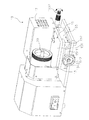
本考案に係る回転式裁断機のその他詳細な特徴、利点や応用に関しては、添附した図面と関連させ、以下の実施の形態の説明を参照することで、理解されるだろう。図1は、本考案に係る回転式裁断機の斜視図、図2は、本考案に係る回転式裁断機の動作を説明するための分解斜視図、図3は、本考案に係る回転式裁断機の部品を説明するための分解斜視図、図4は、本考案に係る回転式裁断機の要部拡大断面図、図5は、本考案に係る回転式裁断機の管材裁断動作を示す説明図である。 Other detailed features, advantages, and applications of the rotary cutter according to the present invention will be understood by referring to the following description of the embodiments in connection with the attached drawings. FIG. 1 is a perspective view of a rotary cutting machine according to the present invention, FIG. 2 is an exploded perspective view for explaining the operation of the rotary cutting machine according to the present invention, and FIG. 3 is a rotary cutting machine according to the present invention. 4 is an exploded perspective view for explaining parts of the machine, FIG. 4 is an enlarged cross-sectional view of a main part of the rotary cutting machine according to the present invention, and FIG. 5 is an explanation showing a pipe material cutting operation of the rotary cutting machine according to the present invention. FIG.
図1〜3を参照し、本考案に係る回転式裁断機の機台10の一側には、カッタ12を回転させるための第1駆動源11が設けられている。機台10の他側に配置されるカッタ12の刃部と互いに隣接する位置には、裁断対象物20(金属管やドリル等)を予め挟持するための治具13が設けられている。治具13と互いに隣接する一側には、第2駆動源14が配置されており、治具13を逆(反対)方向に回転させるために使用される。治具13は、機台10上の移動装置15に載置されている。
With reference to FIGS. 1-3, the
図5に示されるように、裁断対象物20を裁断する際、第1駆動源11は、カッタ12を正回転させ、第2駆動源14は、裁断対象物20を逆方向に回転させる。移動装置15は、治具13をカッタ12の刃部に移動させ、その挟持している裁断対象物20を刃部に接触させ、両者の相反する方向の回転により、迅速かつ精密な裁断作業を進行させる。裁断対象物20の半径距離Dを裁断するだけで、全部が裁断されることとなるため、作業効率、精度および品質が向上する。
As shown in FIG. 5, when the
図1〜図4を同時に参照し、治具13は、機台10の固定板1520の挿入口131に挿入するためのT型ニップル(管)132を備えている。T型ニップル132の一端は、挿入口131に挿入される。T型ニップル132の他端は、一端に比較して、やや大きい外径を有しており、一端が挿入口131に挿入された際、挿入口131の外部に突出して露出したフランジ部133を形成する。裁断対象物20は、1つのスリーブ134によって被覆され、T型ニップル132に挿入自在である。スリーブ134は、本体部1341と副体部1342とからなり、本体部1341と副体部1342の相対している面には、螺合部1345が配置され、両者は螺合部1345を介して連結されている。スリーブ134の内周部には、傾斜状のパッキン縁が形成され、中空円筒形のクランプ1343が挿入される。スリーブ134の内径は、クランプ1343の外径に対応しており、スリーブ134は、クランプ1343を挟持している。クランプ1343の両端部間には、軸方向の割り溝部1344が設けられている。クランプ1343の外周部には、本体部1341および副体部1342のパッキン縁と位置合せされた(対応する)パッキン部が形成されている。クランプ1343の内周部には、後端に位置する大径のクランプ部および前端に位置する小径の締付け部を有する。クランプ部の直径は、挟持される裁断対象物20の大径部の外径と一致している。締付け部の直径は、裁断対象物20の小径部の外径と一致している。
1 to 4, the
図1〜3を再度参照し、第1駆動源11は、モータを使用しており、その前端は機台10の固定板16に取り付けられている。カッタ12は円盤体からなり(円盤状の形状を有し)、モータの回転軸に取り付けられており(連結されており)、モータに駆動されて回転するように設定されている。
1 to 3 again, the
図1〜3を再度参照し、第2駆動源14もまた、モータを使用しており、その前端は移動装置15の固定板1510に取り付けられている。モータの回転軸には、ベルト車が連結されている。ベルト車と治具13との間には、ベルト141が巻かれている。ベルト141の一端および他端は、ベルト車および治具13にそれぞれ巻かれており、モータは、ベルト141を介して治具13を駆動し、カッタ12の回転方向に対して逆方向に回転させるために使用される。
1 to 3 again, the
図1〜3を再度参照し、治具13の前端は、移動装置15のもう1つの固定板1520に枢設(回転自在に配置)されており、第2駆動源14に駆動されて回転する。したがって、裁断対象物20の前端を、固定板1520から突出させてカッタ12と接触させることで、裁断が実行される。
1 to 3 again, the front end of the
図1〜3を再度参照し、移動装置15には1つの主固定底板151が設けられ、その下方には第1微調整スライダ(移動の微調整用送り台)152が固設され、その底面には、X方向(左右方向)に移動可能とするために、第2微調整スライダ153が動作自在に嵌設されている。第2微調整スライダ153は、第1微調整スライダ152の底面でX方向に移動自在である。また、第2微調整スライダ153の底面には、Y方向(前後方向)に移動可能とするために、第3微調整スライダ154が動作自在に嵌設されている。第3微調整スライダ154は、第2微調整スライダ153の底面でY方向に移動自在である。
1 to 3 again, the moving
図1〜3を再度参照し、第1微調整スライダ152の一側には、第1微調整固定座1521が設けられている。第1微調整固定座1521の中には、1つの連結ロッド(杆)1523が取り付けられている。また、第2微調整スライダ153の一側には、第2微調整固定座1531が設けられている。第2微調整固定座1531の中には、1つの微調整ロッド1532が取り付けられている。微調整ロッド1532の前端は、連結ロッド1523の末端に設けられるねじ穴に、螺合している。したがって、微調整ロッド1532の後端を捻転させることで、第1微調整固定座1521はX方向に移動し、そして、第2微調整スライダ153もX方向に移動する。このように、微調整ロッド1532を捻転することにより、第2微調整スライダ153は、主固定底板151を駆動して、これをX方向に移動させ、また、治具13もX方向に駆動されて、裁断対象物20の前端の突出あるいは後退の距離が調整されることになる。
1 to 3 again, a first fine
図1〜3を再度参照し、第3微調整スライダ154の一側には、微調整螺ロッド1541が取り付けられており、第3微調整スライダ154の一側に設けられたねじ穴と螺合している。微調整螺ロッド1541の末端には、1つの回転ディスク1542が配置されており、その上には1つの取手1543が枢設されている。したがって、取手1543を使用して回転ディスク1542を回転させると、第3微調整スライダ154はY方向に移動し、主固定底板151および治具13も共にY方向に駆動され、裁断対象物20は、カッタ12と接触して裁断されることになる、
図1〜3を再度参照し、治具13の上方には、第2駆動源14および治具13を保護するためのカバー17が設けられている。
1 to 3 again, a fine
1-3, a
以上のように、本考案に係る回転式裁断機は、裁断対象物をクランプで確実に挟持し、治具によって回転させながら裁断するので、従来のカッタ工具に比べ、裁断作業の効率および品質を向上させることが可能である。本考案はその形態において、従来品に比べ、幾多の機能を追加していており、新規性および進歩性に係る実用新案登録の法定要件に十分合致するものと確信する。 As described above, the rotary cutting machine according to the present invention securely clamps the object to be cut with a clamp and cuts it while rotating it with a jig, so that the efficiency and quality of the cutting work is improved compared to the conventional cutter tool. It is possible to improve. The present invention, in its form, adds a number of functions compared to the conventional products, and I am convinced that it fully meets the legal requirements for utility model registration concerning novelty and inventive step.
なお、以上の詳細な説明は、本考案の実行可能な実施形態に関する具体的説明であり、これらの実施形態は、本考案に係る実用新案登録請求の範囲を制限するものではなく、およそ本考案の技術精神を逸脱せずなされた同等効果の実施または変更は、全て本考案係る実用新案登録請求の範囲に含まれる。つまり、本考案は、上述した実施の形態に限定されるものではなく、実用新案登録請求の範囲の範囲内で種々改変することができる。 It should be noted that the above detailed description is a specific description of the feasible embodiments of the present invention, and these embodiments do not limit the scope of the utility model registration request according to the present invention, and are approximately the present invention. Any implementation or modification of the equivalent effect without departing from the technical spirit of the present invention is included in the scope of the utility model registration claim of the present invention. That is, the present invention is not limited to the above-described embodiments, and various modifications can be made within the scope of the claims for utility model registration.
10 機台、
11 第1駆動源、
12 カッタ、
13 治具、
14 第2駆動源、
15 移動装置、
16 固定板、
17 カバー、
20 裁断対象物、
131 挿入口、
132 T型ニップル、
133 フランジ部、
134 スリーブ、
141 ベルト、
151 主固定底板、
152 第1微調整スライダ、
153 第2微調整スライダ、
154 第3微調整スライダ、
1341 本体部、
1342 副体部、
1343 クランプ、
1344 割り溝部、
1345 螺合部、
1510 固定板、
1520 固定板、
1521 第1微調整固定座、
1523 連結ロッド、
1531 第2微調整固定座、
1532 微調整ロッド、
1541 微調整螺ロッド、
1542 回転ディスク、
1543 取手。
10 units,
11 First drive source,
12 cutters
13 Jig,
14 Second drive source,
15 mobile device,
16 fixing plate,
17 Cover,
20 Objects to be cut,
131 insertion slot,
132 T-type nipple,
133 flange part,
134 sleeve,
141 belt,
151 main fixed bottom plate,
152 first fine adjustment slider,
153 second fine adjustment slider;
154 Third fine adjustment slider,
1341 main body,
1342 subbody part,
1343 clamp,
1344 split groove,
1345 threaded part,
1510 fixing plate,
1520 fixing plate,
1521 1st fine adjustment fixing seat,
1523 connecting rod,
1531 second fine adjustment fixing seat,
1532 fine adjustment rod,
1541 fine adjustment screw rod,
1542 rotating disc,
1543 Toride.
Claims (9)
前記機台の一側に設けられ、カッタを回転させるための第1駆動源、
前記機台の他側に設けられ、かつ、前記カッタの刃部と互いに隣接する位置に配置され、裁断対象物を予め挟持するための治具、および、
前記治具と互いに隣接する一側に設けられ、かつ、前記カッタの回転方向に対して逆方向に、前記治具を回転させるための第2駆動源を有しており、
前記治具は、前記機台に設けられる移動装置に載置されており、
前記裁断対象物を裁断する際、前記第1駆動源は、前記カッタを回転させ、前記第2駆動源は、前記裁断対象物を逆方向に回転させ、
前記移動装置は、前記治具を前記カッタの刃部に移動させ、前記治具によって挟持される裁断対象物を刃部に接触させることで、前記カッタおよび前記裁断対象物の相反する方向の回転により、前記裁断対象物を迅速かつ精密に裁断する
ことを特徴とする回転式裁断機。 A rotary cutting machine mounted on a machine base,
A first drive source provided on one side of the machine base for rotating the cutter;
A jig that is provided on the other side of the machine base and is disposed at a position adjacent to the blade portion of the cutter, and for holding a cutting object in advance; and
A second drive source for rotating the jig in a direction opposite to the rotation direction of the cutter, provided on one side adjacent to the jig;
The jig is placed on a moving device provided on the machine base,
When cutting the cutting object, the first driving source rotates the cutter, the second driving source rotates the cutting object in the reverse direction,
The moving device moves the jig to the blade part of the cutter, and causes the cutting object sandwiched by the jig to contact the blade part, thereby rotating the cutter and the cutting object in opposite directions. The rotary cutting machine is characterized in that the cutting object is cut quickly and precisely.
前記T型ニップルは、前記挿入口に挿入される一端および前記一端に比較して、やや大きい外径の他端を有しており、
前記他端は、前記一端が前記挿入口に挿入された際、前記挿入口の外部に突出して露出したフランジ部を形成し、
前記裁断対象物は、1つのスリーブによって被覆され、前記T型ニップルに挿入自在であり、
前記スリーブは、本体部と副体部とからなり、前記本体部と前記副体部の相対している面には、螺合部が配置され、前記螺合部を介して連結しており、
前記スリーブの内周部には、傾斜状のパッキン縁が形成され、かつ、中空円筒形のクランプが挿入されており、前記スリーブの内径は、前記クランプの外径に対応し、前記スリーブは、前記クランプを挟持しており、
前記クランプは、両端部間に設けられる軸方向の割り溝部、前記本体部および前記副体部のパッキン縁と位置合せされたパッキン部が形成される外周部、および、後端に位置する大径のクランプ部および前端に位置する小径の締付け部を有する内周部を有し、
前記クランプ部の直径および締付け部の直径は、挟持される前記裁断対象物の大径部の外径および小径部の外径と一致している
ことを特徴とする請求項1に記載の回転式裁断機。 The jig includes a T-shaped nipple for insertion into an insertion port of the fixing plate of the machine base,
The T-shaped nipple has one end inserted into the insertion port and the other end having a slightly larger outer diameter than the one end.
The other end forms a flange portion that protrudes and is exposed outside the insertion port when the one end is inserted into the insertion port.
The object to be cut is covered by a single sleeve and can be inserted into the T-shaped nipple.
The sleeve is composed of a main body portion and a sub body portion, and a screwing portion is disposed on the opposing surfaces of the main body portion and the sub body portion, and is connected via the screwing portion,
An inclined packing edge is formed on the inner peripheral portion of the sleeve, and a hollow cylindrical clamp is inserted, the inner diameter of the sleeve corresponds to the outer diameter of the clamp, Holding the clamp,
The clamp has an axial dividing groove provided between both end portions, an outer peripheral portion formed with a packing portion aligned with packing edges of the main body portion and the sub body portion, and a large diameter located at the rear end. And an inner peripheral portion having a small-diameter fastening portion located at the front end,
2. The rotary type according to claim 1, wherein a diameter of the clamp part and a diameter of the tightening part coincide with an outer diameter of a large diameter part and an outer diameter of a small diameter part of the object to be cut. Cutting machine.
前記モータの前端は前記機台の固定板に取り付けられており、
前記カッタは円盤体からなり、前記モータの回転軸に取り付けられており、前記モータに駆動されて回転する
ことを特徴とする請求項1に記載の回転式裁断機。 The first drive source uses a motor,
The front end of the motor is attached to the stationary plate of the machine base,
The rotary cutter according to claim 1, wherein the cutter is formed of a disc body, is attached to a rotation shaft of the motor, and is rotated by being driven by the motor.
前記モータの前端は、前記移動装置の固定板に取り付けられ、前記モータの回転軸には、ベルト車が連結されており、
前記ベルト車と前記治具との間には、ベルトが巻かれており、
前記ベルトの一端および他端は、前記ベルト車および前記治具にそれぞれ位置し、
前記モータは、前記ベルトを介して前記治具を駆動し、前記カッタの回転方向に対して逆方向に回転させる
ことを特徴とする請求項1に記載の回転式裁断機。 The second drive source uses a motor,
A front end of the motor is attached to a fixed plate of the moving device, and a belt wheel is connected to a rotation shaft of the motor,
A belt is wound between the belt wheel and the jig,
One end and the other end of the belt are respectively located on the belt wheel and the jig,
The rotary cutter according to claim 1, wherein the motor drives the jig through the belt and rotates the jig in a direction opposite to a rotation direction of the cutter.
前記裁断対象物の前端を、前記固定板から突出させて前記カッタと接触させることで、裁断を実行する
ことを特徴とする請求項1に記載の回転式裁断機。 The front end of the jig is pivotally mounted on the fixed plate of the moving device, and is set to rotate by being driven by the second drive source.
The rotary cutter according to claim 1, wherein cutting is performed by causing a front end of the cutting object to protrude from the fixed plate and contact the cutter.
1つの主固定底板、
前記主固定底板の下方に固設される第1微調整スライダ、
前記第1微調整スライダの底面で左右方向であるX方向に移動自在である第2微調整スライダ、および、
前記第2微調整スライダの底面で前後方向であるY方向に移動自在である第3微調整スライダを有しており、
前記第2微調整スライダは、X方向に移動可能とするために、前記第1微調整スライダの底面に動作自在に嵌設され、
前記第3微調整スライダは、Y方向に移動可能とするために、前記第2微調整スライダ153の底面に動作自在に嵌設されている
ことを特徴とする請求項1に記載の回転式裁断機。 The mobile device is
One main fixed bottom plate,
A first fine adjustment slider fixed below the main fixed bottom plate;
A second fine adjustment slider which is movable in the X direction which is the left-right direction on the bottom surface of the first fine adjustment slider; and
Having a third fine adjustment slider which is movable in the Y direction which is the front-rear direction on the bottom surface of the second fine adjustment slider;
The second fine adjustment slider is movably fitted on the bottom surface of the first fine adjustment slider so as to be movable in the X direction.
The rotary cutting according to claim 1, wherein the third fine adjustment slider is movably fitted on the bottom surface of the second fine adjustment slider 153 so as to be movable in the Y direction. Machine.
前記第2微調整スライダの一側には、第2微調整固定座が設けられ、前記第2微調整固定座の中には、1つの微調整ロッドが取り付けられており、
前記微調整ロッドの前端は、前記連結ロッドの末端に設けられるねじ穴に螺合しており、
前記微調整ロッドの後端を捻転させることで、前記第1微調整固定座はX方向に移動し、そして、前記第2微調整スライダもX方向に移動するように構成されており、
前記微調整ロッドを捻転することにより、前記第2微調整スライダは、前記主固定底板を駆動してX方向に移動させ、また、前記治具もX方向に駆動されるため、前記裁断対象物の前端の突出あるいは後退の距離が調整される
ことを特徴とする請求項6に記載の回転式裁断機。 A first fine adjustment fixing seat is provided on one side of the first fine adjustment slider, and a connecting rod is attached to the first fine adjustment fixing seat.
A second fine adjustment fixing seat is provided on one side of the second fine adjustment slider, and one fine adjustment rod is attached in the second fine adjustment fixing seat,
The front end of the fine adjustment rod is screwed into a screw hole provided at the end of the connecting rod,
The first fine adjustment fixing seat is moved in the X direction by twisting the rear end of the fine adjustment rod, and the second fine adjustment slider is also moved in the X direction.
By twisting the fine adjustment rod, the second fine adjustment slider drives the main fixed bottom plate to move in the X direction, and the jig is also driven in the X direction. The rotary cutting machine according to claim 6, wherein a distance of protrusion or retraction of the front end of the rotary cutter is adjusted.
前記微調整螺ロッドは、前記第3微調整スライダの一側に設けられたねじ穴と螺合しており、前記微調整螺ロッドの末端には、1つの取手が枢設されている1つの回転ディスクが配置されており、
前記取手を使用して前記回転ディスクを回転させると、前記第3微調整スライダは、Y方向に移動し、前記主固定底板および前記治具も共に、Y方向に駆動され、前記裁断対象物は、前記カッタと接触して裁断される
ことを特徴とする請求項6に記載の回転式裁断機。 A fine adjustment screw rod is attached to one side of the third fine adjustment slider,
The fine adjustment screw rod is screwed into a screw hole provided on one side of the third fine adjustment slider, and one handle having a handle pivoted at the end of the fine adjustment screw rod. A rotating disk is located,
When the rotary disk is rotated using the handle, the third fine adjustment slider moves in the Y direction, the main fixed bottom plate and the jig are both driven in the Y direction, and the object to be cut is The rotary cutter according to claim 6, wherein the cutter is cut in contact with the cutter.
Applications Claiming Priority (1)
| Application Number | Priority Date | Filing Date | Title |
|---|---|---|---|
| TW97202650U TWM338738U (en) | 2008-02-13 | 2008-02-13 | Rotation type cutting machine |
Publications (2)
| Publication Number | Publication Date |
|---|---|
| JP3146434U true JP3146434U (en) | 2008-11-13 |
| JP3146434U7 JP3146434U7 (en) | 2009-07-30 |
Family
ID=43296144
Family Applications (1)
| Application Number | Title | Priority Date | Filing Date |
|---|---|---|---|
| JP2008006249U Expired - Lifetime JP3146434U (en) | 2008-02-13 | 2008-09-04 | Rotary cutter |
Country Status (2)
| Country | Link |
|---|---|
| JP (1) | JP3146434U (en) |
| TW (1) | TWM338738U (en) |
-
2008
- 2008-02-13 TW TW97202650U patent/TWM338738U/en not_active IP Right Cessation
- 2008-09-04 JP JP2008006249U patent/JP3146434U/en not_active Expired - Lifetime
Also Published As
| Publication number | Publication date |
|---|---|
| TWM338738U (en) | 2008-08-21 |
Similar Documents
| Publication | Publication Date | Title |
|---|---|---|
| JP2009542453A (en) | Improved pipe cutting device and method of use thereof | |
| CN101918165B (en) | Multi-purpose beveller | |
| US6581499B2 (en) | Automated pipe cutter tool box | |
| CN109963673A (en) | Device for machining pipes and/or pipe flanges | |
| CN101304830A (en) | Device for machining the end of a tubular component | |
| CN118455689A (en) | Pipeline groove processing method and processing device | |
| CN113787366B (en) | Seal Weld Cutting Tools | |
| CN209140410U (en) | A kind of motor shaft fraise jig | |
| CN215035556U (en) | Fixed frock for milling machine | |
| CN211991852U (en) | Machining clamp for special-shaped target | |
| CN117358993B (en) | A portable air pipe end chamfering tool | |
| WO2009111913A1 (en) | A rotary cutting machine | |
| CN224043924U (en) | Portable plastic pipe cutting device | |
| TWM560366U (en) | Clip locking positioning device for rotation axis of machining spindle | |
| CN219633118U (en) | A CNC machine tool for easy disassembly and conversion | |
| CN222059079U (en) | Universal clamp for machining shaft parts of linear cutting machine | |
| CN214723499U (en) | An angle vise | |
| CN213531565U (en) | Steel pipe cutting device | |
| CN220554972U (en) | A pipeline intersecting line welding device | |
| CN214080995U (en) | Flat key positioning structure | |
| CN223210979U (en) | An easily adjustable tool magazine loose tool block for drilling and tapping machines | |
| JP2011206855A (en) | Pipe cutter | |
| CN223519206U (en) | A tool holder type robot for CNC machine tools | |
| KR102736273B1 (en) | Clamp for fixing ring-shaped processing objects | |
| CN222779445U (en) | A magnesium alloy gearbox fixture for garden tools |
Legal Events
| Date | Code | Title | Description |
|---|---|---|---|
| A521 | Request for written amendment filed |
Free format text: JAPANESE INTERMEDIATE CODE: A821 Effective date: 20080905 |
|
| R150 | Certificate of patent or registration of utility model |
Free format text: JAPANESE INTERMEDIATE CODE: R150 |
|
| FPAY | Renewal fee payment (event date is renewal date of database) |
Free format text: PAYMENT UNTIL: 20111022 Year of fee payment: 3 |
|
| A623 | Registrability report |
Free format text: JAPANESE INTERMEDIATE CODE: A623 Effective date: 20081218 |
|
| FPAY | Renewal fee payment (event date is renewal date of database) |
Free format text: PAYMENT UNTIL: 20111022 Year of fee payment: 3 |
|
| R231 | Written correction (descriptions, etc.) |
Free format text: JAPANESE INTERMEDIATE CODE: R231 |
|
| FPAY | Renewal fee payment (event date is renewal date of database) |
Free format text: PAYMENT UNTIL: 20111022 Year of fee payment: 3 |
|
| R157 | Certificate of patent or utility model (correction) |
Free format text: JAPANESE INTERMEDIATE CODE: R157 |
|
| A623 | Registrability report |
Free format text: JAPANESE INTERMEDIATE CODE: A623 Effective date: 20090907 |
|
| FPAY | Renewal fee payment (event date is renewal date of database) |
Free format text: PAYMENT UNTIL: 20111022 Year of fee payment: 3 |
|
| FPAY | Renewal fee payment (event date is renewal date of database) |
Free format text: PAYMENT UNTIL: 20121022 Year of fee payment: 4 |
|
| FPAY | Renewal fee payment (event date is renewal date of database) |
Free format text: PAYMENT UNTIL: 20121022 Year of fee payment: 4 |
|
| FPAY | Renewal fee payment (event date is renewal date of database) |
Free format text: PAYMENT UNTIL: 20131022 Year of fee payment: 5 |
|
| R250 | Receipt of annual fees |
Free format text: JAPANESE INTERMEDIATE CODE: R250 |
|
| R250 | Receipt of annual fees |
Free format text: JAPANESE INTERMEDIATE CODE: R250 |
|
| R250 | Receipt of annual fees |
Free format text: JAPANESE INTERMEDIATE CODE: R250 |
|
| R250 | Receipt of annual fees |
Free format text: JAPANESE INTERMEDIATE CODE: R250 |
|
| R250 | Receipt of annual fees |
Free format text: JAPANESE INTERMEDIATE CODE: R250 |
|
| EXPY | Cancellation because of completion of term |