JP3146587U - Golf putter - Google Patents
Golf putter Download PDFInfo
- Publication number
- JP3146587U JP3146587U JP2008006422U JP2008006422U JP3146587U JP 3146587 U JP3146587 U JP 3146587U JP 2008006422 U JP2008006422 U JP 2008006422U JP 2008006422 U JP2008006422 U JP 2008006422U JP 3146587 U JP3146587 U JP 3146587U
- Authority
- JP
- Japan
- Prior art keywords
- golf ball
- golf
- putter
- hole
- holding hole
- Prior art date
- Legal status (The legal status is an assumption and is not a legal conclusion. Google has not performed a legal analysis and makes no representation as to the accuracy of the status listed.)
- Expired - Fee Related
Links
Images


Landscapes
- Golf Clubs (AREA)
Abstract
【課題】ストロークの正確性に悪影響を与えることがないとともに、ゴミや水分が付着していても立ったままで確実にゴルフボールを拾い上げることができるパターヘッドを有するゴルフパターを提供する。
【解決手段】ホールカップに挿入可能な大きさを有するパターヘッド2の底面13に有底孔である保持孔5を凹設したゴルフパターであって、底面13上に形成された保持孔5の開口面は、ゴルフボール20の直径部位を開口面付近の保持孔5の内側壁で押圧して挟持可能な大きさを有し、保持孔5の深さは、ゴルフボール20の半径よりも長い。
【選択図】図4Provided is a golf putter having a putter head that does not adversely affect the accuracy of a stroke and can reliably pick up a golf ball while standing even if dust or moisture is attached.
A golf putter having a holding hole (5) having a bottomed hole formed in a bottom surface (13) of a putter head (2) having a size that can be inserted into a hole cup, the holding hole (5) formed on the bottom surface (13). The opening surface has a size that allows the diameter portion of the golf ball 20 to be pressed and clamped by the inner wall of the holding hole 5 near the opening surface, and the depth of the holding hole 5 is longer than the radius of the golf ball 20. .
[Selection] Figure 4
Description
本考案は、ゴルフパターに関し、特に、ゴルフパターのヘッドに関する。 The present invention relates to a golf putter, and more particularly to a golf putter head.
従来から、ホールインしたゴルフボールをカップから取り出したり、練習グリーン上にあるゴルフボールを拾い上げたりする動作は、腰をかがめるとともに、腕を下方に伸ばしてゴルフボールを拾い上げる必要があるため、腰痛持ちや高齢者のプレーヤーにとっては苦痛を伴う動作であった。また、腰痛持ちや高齢者のプレーヤーでなくても、腰をかがめてゴルフボールを拾い上げる動作を面倒に感じるプレーヤーも存在する。 Conventionally, taking out a golf ball that has been holed in from a cup or picking up a golf ball on the practice green requires bending back and stretching your arm downwards to pick up the golf ball. It was a painful movement for older players. In addition, there are players who are troublesome to bend their hips and pick up a golf ball, even if they are not back and elderly players.
そのため、腰をかがめることなく、立ったままゴルフボールを拾い上げることができるゴルフパターが知られている(例えば、特許文献1、2参照)。このゴルフパターは、パターヘッドの後部にゴルフボールを嵌合可能な貫通孔を形成し、この貫通孔をゴルフボールに押し当てて、貫通孔の内周面がゴルフボールを保持することにより、立ったままでゴルフボールを拾い上げるようにしている。 Therefore, golf putters that can pick up a golf ball while standing without bending down are known (see, for example, Patent Documents 1 and 2). This golf putter is formed by forming a through hole into which the golf ball can be fitted at the rear part of the putter head, pressing the through hole against the golf ball, and holding the golf ball on the inner peripheral surface of the through hole. The golf ball is picked up while standing.
ところで、ゴルフパターの最も重要な機能は、グリーン上にあるゴルフボールを的確にヒットしてホールカップに入れる正確性にある。したがって、ゴルフパターには、当然のこととして、パッティング時のストロークの安定性を高めることやフェース面の方向性を高めることが求められている。 By the way, the most important function of the golf putter is the accuracy of accurately hitting the golf ball on the green and putting it in the hole cup. Therefore, as a matter of course, the golf putter is required to increase the stability of the stroke when putting and to improve the directionality of the face surface.
しかしながら、上述したパターヘッドに貫通孔を形成したゴルフパターにおいては、ストローク時に、パターヘッドに形成された貫通孔より、グリーン上の芝が目に入るため、ゴルフパターを正しい方向に向けることやゴルフパターを正しい軌道でストロークすることに狂いが生じ、ゴルフボールを意図するところへヒットすることができない可能性がある。すなわち、この場合には、芝の形状や色など芝の状態は、場所が違えばすべて微妙に異なっているため、ストローク中に目に飛び込むこの芝の状態の変化が、ストロークする前に決めたプレーヤーの感覚に微妙な変化を与え、ストロークの正確性を欠く要因になるという問題がある。 However, in the golf putter in which the through hole is formed in the putter head described above, the grass on the green is visible to the eyes from the through hole formed in the putter head during the stroke. Stroking the putter in the correct trajectory can lead to inaccuracies that prevent the golf ball from being hit as intended. In other words, in this case, the grass conditions such as the shape and color of the turf are all slightly different at different locations, so this change in the turf state that jumps into the eyes during the stroke was decided before the stroke. There is a problem in that it gives subtle changes to the player's senses and causes a lack of stroke accuracy.
また、上述したパターヘッドに貫通孔を形成したゴルフパターにおいては、貫通孔の内壁がゴルフボールの中心よりも上方位置の外周部分を保持しているので、ゴルフボールにゴミや水分が付着している場合には、保持力が十分でなく、場合によってはゴルフボールを拾い上げることができないという問題もある。 Further, in the golf putter in which the above-described putter head has a through hole, the inner wall of the through hole holds the outer peripheral portion at a position higher than the center of the golf ball, so that dust and moisture adhere to the golf ball. If it is, the holding force is not sufficient, and in some cases, there is a problem that the golf ball cannot be picked up.
本考案は上記の事情を鑑みてなされたものであり、ストロークの正確性に悪影響を与えることがないとともに、ゴミや水分が付着していても立ったままで確実にゴルフボールを拾い上げることができるパターヘッドを有するゴルフパターを提供することを目的とする。 The present invention has been made in view of the above circumstances, and does not adversely affect the accuracy of the stroke, and can reliably pick up a golf ball while standing even if dust or moisture is attached. An object is to provide a golf putter having a head.
上記の課題を達成するため、本考案は、その一態様として、ホールカップに挿入可能な大きさを有するパターヘッドの底面に有底孔を凹設したゴルフパターであって、前記底面上に形成された前記有底孔の開口面は、ゴルフボールの直径部位を前記開口面付近の前記有底孔の内側壁で押圧して挟持可能な大きさを有し、前記有底孔の深さは、前記ゴルフボールの半径よりも長いことを特徴とする。 In order to achieve the above object, the present invention, as one aspect thereof, is a golf putter having a bottomed hole formed in a bottom surface of a putter head having a size that can be inserted into a hole cup, and formed on the bottom surface. The bottomed hole opening surface has a size capable of pressing and sandwiching the diameter portion of the golf ball with the inner wall of the bottomed hole near the opening surface, and the depth of the bottomed hole is The golf ball is longer than the radius of the golf ball.
本考案の一態様のゴルフパターにおいては、パターヘッドにゴルフボールを挟持する孔が開設されているが、貫通孔ではなく有底孔であるので、プレーヤーは、ストローク時に孔を介してグリーン上の芝が目に入ることがない。したがって、本考案の一態様のゴルフパターは、ストロークの正確性に悪影響を与えることがない。 In the golf putter according to one aspect of the present invention, a hole for holding the golf ball is formed in the putter head. However, since the hole is not a through hole but a bottomed hole, I can't see the grass. Therefore, the golf putter of one aspect of the present invention does not adversely affect the accuracy of the stroke.
また、有底孔の開口面は、ゴルフボールの直径部位を開口面付近の有底孔の内側壁で押圧して挟持可能な大きさを有するとともに、有底孔の深さは、ゴルフボールの半径よりも長いので、ゴルフボールを直径部位で確実に保持することができる。したがって、本考案の一態様のゴルフパターは、ゴミや水分が付着していても立ったままで確実にゴルフボールを拾い上げることができる。 The opening surface of the bottomed hole has a size that allows the diameter portion of the golf ball to be pressed and clamped by the inner wall of the bottomed hole near the opening surface. Since it is longer than the radius, the golf ball can be reliably held at the diameter portion. Therefore, the golf putter of one embodiment of the present invention can reliably pick up the golf ball while standing even if dust or moisture is attached.
また、前記パターヘッドは、平面視D型形状の外形を有し、前記有底孔の開口面は、目玉状に形成され、その目玉状の一側は、前記D型形状の外形曲線に沿って僅か内側に形成され、前記ゴルフボールは、前記目玉状の開口面の中央部分にて前記有底孔の内側壁に挟持され、前記目玉状の開口面近傍の内側壁におけるゴルフボール挟持部位間の距離は、前記ゴルフボールの直径より僅かに小さいことを特徴とする。これにより、ゴルフボールがホールカップのどの位置にあっても、確実に挟持してゴルフボールを拾い上げることができる。また、ゴルフボールを挟持した状態においては、目玉状の開口面の両端部には指が入る隙間が形成されるので、挟持したゴルフボールを簡単に取り外すことができる。 Further, the putter head has a D-shaped outer shape in plan view, and the opening surface of the bottomed hole is formed in an eyeball shape, and one side of the eyeball shape follows the outer contour curve of the D-shaped shape. The golf ball is sandwiched between the inner wall of the bottomed hole at the center portion of the eyeball-shaped opening surface, and between the golf ball sandwiching sites on the inner wall near the eyeball-shaped opening surface. The distance is slightly smaller than the diameter of the golf ball. Accordingly, the golf ball can be reliably pinched and picked up regardless of the position of the hole in the hole cup. In addition, in the state where the golf ball is sandwiched, a gap for inserting a finger is formed at both ends of the eyeball-shaped opening surface, so that the sandwiched golf ball can be easily removed.
本考案によれば、ストロークの正確性に悪影響を与えることがないとともに、ゴミや水分が付着していても立ったままで確実にゴルフボールを拾い上げることができるパターヘッドを有するゴルフパターを提供することができる。 According to the present invention, it is possible to provide a golf putter having a putter head that does not adversely affect the accuracy of a stroke and can reliably pick up a golf ball while standing even if dust or moisture is attached. Can do.
以下、本考案の実施の形態を図面を用いて説明する。 Hereinafter, embodiments of the present invention will be described with reference to the drawings.
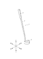
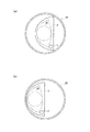
図1は、本考案の実施の形態に係るゴルフパター1の外観斜視図、図2は、本考案の実施の形態に係るゴルフパター1のパターヘッド2の平面図、図3は、本考案の実施の形態に係るゴルフパター1のパターヘッド2の背面図、図4は、本考案の実施の形態に係るゴルフパター1のパターヘッド2の底面図である。また、図5は、図2のA−A線に沿った断面図であり、図6は、ホールカップ30内において、ゴルフパター1の保持孔5にゴルフボール20を嵌め込んだ状態を模式的に示した平面図である。
FIG. 1 is an external perspective view of a golf putter 1 according to an embodiment of the present invention, FIG. 2 is a plan view of a
ゴルフパター1は、マレット型のヘッド形状を有するゴルフパターであり、図1に示すように、パターヘッド2と、一端がパターヘッド2に固定されたシャフト3と、シャフト3の他端に固定されたグリップ4と、を備える。なお、以下においては、図1に示すように、パターヘッド2のフェース面11側(ゴルフボール20の進行方向)を前、その反対側を後、パターヘッド2のシャフト取付側を上、地面と接するソール側を下、ゴルフパター1を構えたときの手前側(ヒール)を左、先側(トウ)を右と称して説明を行う。
The golf putter 1 is a golf putter having a mallet type head shape. As shown in FIG. 1, the golf putter 1 is fixed to the
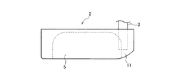
パターヘッド2は、その外形が平面視D型形状を有し、上面12には、図2に示すように、3本の直線からなる目標線15がフェース面11に垂直に設けられているとともに、底面(ソール面)13には、図3及び図4に示すように、ゴルフボール20を嵌合可能な保持孔5が穿設されている。なお、パターヘッド2の大きさは、ホールカップ30に余裕(隙間)を持ってパターヘッド2を挿入することができる程度の大きさとなっている(図6参照)。
The outer shape of the
プレーヤーがパッティングする際には、この上面に設けられた目標線15を利用して、フェース面11の方向を決定するとともに、ストローク軌道を決定する。すなわち、目標線15は、パッティングの正確性を高めるために形成されたものであり、パッティングの方向や力加減を支援するツールとなっている。本実施の形態においては、目標線15として、フェース面11に垂直な3本の直線を描いたが、目標線はこのデザインに限定されるものではなく、他のデザインであってもよいのは勿論であり、円形状、T字状、矩形状などの目標線15を上面に描くようにしてもよい。
When the player puts, the
保持孔5は、図3及び図4に示すように、底面13から凹設された有底孔であり、底面13に形成された開口面は、左右方向に長く前後方向に短い略目玉状をなしている。その結果、保持孔5は、ゴルフボール20の直径部位(ゴルフボール20の表面上におけるゴルフボール20の直径Dの一端及び他端部分)を前後方向に対向する内側壁支持部16及び17で挟持して、保持するようになっている。本実施の形態では、保持孔5の内側壁支持部16及び17間の距離は、ゴルフボール20の直径寸法(外径)よりも僅かに小さく形成されているが、ゴルフボール20は表面に僅かな弾力性を有しているため、ゴルフボール20をパターヘッド2の保持孔5で押圧することにより、ゴルフボールは若干縮んで保持孔5に挿入され、保持孔に嵌合されるようになっている。
As shown in FIGS. 3 and 4, the
また、保持孔5は、図5に示すように、ゴルフボール20の上半球が完全に嵌り込む高さ(深さ)を有している。すなわち、保持孔5の上下方向の深さは、ゴルフボール20の半径よりも長く形成されている。また、保持孔5の開口面付近の内側壁は、図5に示すように、開口面に略垂直な平面となっており、この平面上の内側壁支持部16及び17でゴルフボール20の直径部位を挟持するようになっている。
Further, as shown in FIG. 5, the
なお、保持孔5の開口面周縁にはわずかな幅の面取り部18が形成されているため、ゴルフボール20は、保持孔5に誘導され、スムースに保持孔5に嵌合されるようになっている。
Since the chamfered
ここで、本考案の実施の形態に係るゴルフパター1の作用について説明する。ゴルフボール20がホールカップ30に入ると、プレーヤーは、まずゴルフパター1のグリップ4を持ち、図6に示すように、パターヘッド2をホールカップ30に入れて、ゴルフボール20の上方に保持孔5が位置するようにゴルフパター1を操作する。次いで、ゴルフボール20をパターヘッド2の保持孔5で押圧すると、ゴルフボール20は保持孔5に挿入され保持されるので、その状態のままゴルフパター1のパターヘッド2を上方に持ち上げるだけで、プレーヤーは腰をかがめることなく楽な姿勢でゴルフボール20を拾い上げることができる。そして、プレーヤーはゴルフボール20が保持された状態の保持孔5に手を挿入してゴルフボール20を保持孔5から取り出す。この際、本実施の形態では、図4に示すように、保持孔5の開口面左右方向には充分な隙間が形成されているので、指を挿入しやすくなっている。
Here, the operation of the golf putter 1 according to the embodiment of the present invention will be described. When the
また、本実施の形態においては、図4に示すように、保持孔5の後方開口面をD型の曲線形状に沿って僅か内側(約4mm)に形成しているので、図6(a)に示すように、ゴルフボール20がホールカップ30の中央にある場合は勿論、図6(b)に示すようにゴルフボール20がホールカップ30の側壁付近にある場合であっても、確実にゴルフボールを挟持して拾い上げることが可能である。すなわち、ホールカップ30の側壁にパターヘッド2の曲面が形成された後方側面を沿わせて、保持孔5がゴルフボール20を押圧すれば、ゴルフボールは側壁から保持孔5方向に誘導されるので、保持孔5はゴルフボールを保持することができる。
Further, in the present embodiment, as shown in FIG. 4, the rear opening surface of the holding
勿論、上述した動作をホールカップ30以外のゴルフボール20に対して行ってもよく、例えば、練習グリーン上のボール20に対して、腰をかがめずに拾い上げるようにしてもよい。
Of course, the above-described operation may be performed on the
以上説明したように、本実施の形態に係るゴルフパター1によれば、パターヘッド2にゴルフボール20を挟持する保持孔5を有底孔として形成しているので、プレーヤーは、ストローク時に保持孔5を介してグリーン上の芝が目に入ることがない。この結果、本実施の形態に係るゴルフパター1によれば、ストロークの正確性に悪影響を与えることがない。
As described above, according to the golf putter 1 according to the present embodiment, the holding
また、本実施の形態に係るゴルフパター1によれば、保持孔5の開口面は、ゴルフボール20の直径部位を開口面付近の保持孔5の内側壁で押圧して挟持可能な大きさを有するとともに、保持孔5の深さは、ゴルフボール20の半径よりも長いので、ゴルフボール20を直径部位で確実に保持することができる。この結果、本実施の形態に係るゴルフパター1によれば、ゴミや水分が付着していたとしても、立ったままで確実にゴルフボールを拾い上げることができる。
In addition, according to the golf putter 1 according to the present embodiment, the opening surface of the holding
また、本実施の形態に係るゴルフパター1によれば、保持孔5の後方開口面をD型の曲線形状に沿って僅か内側に形成しているので、ゴルフボール20がホールカップ30のどの位置にあっても、確実に挟持してゴルフボール20を拾い上げることができる。また、保持孔5の開口面は、ゴルフボール20を挟持した状態において目玉状の両端部に指が入る隙間が形成されているので、挟持したゴルフボール20を簡単に取り外すことができる。
In addition, according to the golf putter 1 according to the present embodiment, the rear opening surface of the holding
さらに、本実施の形態に係るゴルフパター1によれば、パターヘッド2の上面12に目標線15が描かれているので、目標線15を利用して、フェース面11の方向を決定するとともに、ストローク軌道を決定することができるので、ストロークの正確性を向上させることができる。
Furthermore, according to the golf putter 1 according to the present embodiment, since the
なお、上記実施の形態のゴルフパター1では、パターヘッド2に穿設された保持孔5を開口面において目玉状に形成したが、保持孔5の開口面における形状は目玉状に限定されるものではない。また、保持孔5の深さ方向の形状も、図3及び図5に示す限りではない。すなわち、保持孔5の内側壁でゴルフボール20の直径部位を挟持可能とするのであれば、保持孔5の形状はいかなる形状であってもよい。
In the golf putter 1 of the above embodiment, the holding
また、上記実施の形態のゴルフパター1においては、内側壁支持部16及び17でゴルフボール20を挟持するようにしたが、挟持する部位は2箇所に限定されるものではなく、その数はいくつであってもよい。また、挟持する部位の形状も限定されず、点、線、面のいずれで内側壁支持部を形成するようにしてもよい。
Further, in the golf putter 1 of the above embodiment, the
以上、本考案の実施の形態について説明してきたが、本考案は、上述した実施の形態に限られるものではなく、本考案の要旨を逸脱しない範囲において、本考案の実施の形態に対して種々の変形や変更を施すことができ、そのような変形や変更を伴うものもまた、本考案の技術的範囲に含まれるものである。 Although the embodiments of the present invention have been described above, the present invention is not limited to the above-described embodiments, and various modifications can be made to the embodiments of the present invention without departing from the gist of the present invention. Such modifications and changes can be made, and those accompanying such modifications and changes are also included in the technical scope of the present invention.
1 ゴルフパター
2 パターヘッド
3 シャフト
4 グリップ
5 保持孔
11 フェース面
12 上面
13 底面
15 目標線
16,17 内側壁支持部
18 面取り部
20 ゴルフボール
30 ホールカップ
D 直径
DESCRIPTION OF SYMBOLS 1
Claims (2)
前記底面上に形成された前記有底孔の開口面は、ゴルフボールの直径部位を前記開口面付近の前記有底孔の内側壁で押圧して挟持可能な大きさを有し、
前記有底孔の深さは、前記ゴルフボールの半径よりも長いことを特徴とするゴルフパター。 A golf putter having a bottomed hole recessed in the bottom surface of a putter head having a size that can be inserted into a hole cup,
The opening surface of the bottomed hole formed on the bottom surface has a size capable of pressing and pinching the diameter portion of the golf ball with the inner wall of the bottomed hole near the opening surface,
A golf putter characterized in that a depth of the bottomed hole is longer than a radius of the golf ball.
前記有底孔の開口面は、目玉状に形成され、その目玉状の一側は、前記D型形状の外形曲線に沿って僅か内側に形成され、
前記ゴルフボールは、前記目玉状の開口面の中央部分にて前記有底孔の内側壁に挟持され、
前記目玉状の開口面近傍の内側壁におけるゴルフボール挟持部位間の距離は、前記ゴルフボールの直径より僅かに小さいことを特徴とする請求項1記載のゴルフパター。 The putter head has a D-shaped outer shape in plan view.
The opening surface of the bottomed hole is formed in an eyeball shape, and one side of the eyeball shape is formed slightly inside along the outer shape curve of the D shape,
The golf ball is sandwiched between the inner side walls of the bottomed hole at a center portion of the eyeball-shaped opening surface,
The golf putter according to claim 1, wherein a distance between the golf ball holding portions on the inner side wall in the vicinity of the eyeball-shaped opening surface is slightly smaller than a diameter of the golf ball.
Priority Applications (1)
| Application Number | Priority Date | Filing Date | Title |
|---|---|---|---|
| JP2008006422U JP3146587U (en) | 2008-09-11 | 2008-09-11 | Golf putter |
Applications Claiming Priority (1)
| Application Number | Priority Date | Filing Date | Title |
|---|---|---|---|
| JP2008006422U JP3146587U (en) | 2008-09-11 | 2008-09-11 | Golf putter |
Publications (1)
| Publication Number | Publication Date |
|---|---|
| JP3146587U true JP3146587U (en) | 2008-11-20 |
Family
ID=43296292
Family Applications (1)
| Application Number | Title | Priority Date | Filing Date |
|---|---|---|---|
| JP2008006422U Expired - Fee Related JP3146587U (en) | 2008-09-11 | 2008-09-11 | Golf putter |
Country Status (1)
| Country | Link |
|---|---|
| JP (1) | JP3146587U (en) |
Cited By (4)
| Publication number | Priority date | Publication date | Assignee | Title |
|---|---|---|---|---|
| US11813508B2 (en) | 2018-10-01 | 2023-11-14 | Karsten Manufacturing Corporation | Multi-component putter |
| USD1027088S1 (en) | 2022-06-22 | 2024-05-14 | Karsten Manufacturing Corporation | Golf club head |
| USD1028145S1 (en) | 2022-06-22 | 2024-05-21 | Karsten Manufacturing Corporation | Golf club head |
| US12076625B2 (en) | 2022-07-18 | 2024-09-03 | Parsons Xtreme Golf, LLC | Golf club heads and methods to manufacture golf club heads |
-
2008
- 2008-09-11 JP JP2008006422U patent/JP3146587U/en not_active Expired - Fee Related
Cited By (6)
| Publication number | Priority date | Publication date | Assignee | Title |
|---|---|---|---|---|
| US11813508B2 (en) | 2018-10-01 | 2023-11-14 | Karsten Manufacturing Corporation | Multi-component putter |
| US12485325B2 (en) | 2018-10-01 | 2025-12-02 | Karsten Manufacturing Corporation | Multi-component putter |
| USD1027088S1 (en) | 2022-06-22 | 2024-05-14 | Karsten Manufacturing Corporation | Golf club head |
| USD1028145S1 (en) | 2022-06-22 | 2024-05-21 | Karsten Manufacturing Corporation | Golf club head |
| US12076625B2 (en) | 2022-07-18 | 2024-09-03 | Parsons Xtreme Golf, LLC | Golf club heads and methods to manufacture golf club heads |
| US12172060B2 (en) | 2022-07-18 | 2024-12-24 | Parsons Xtreme Golf, LLC | Golf club heads and methods to manufacture golf club heads |
Similar Documents
| Publication | Publication Date | Title |
|---|---|---|
| USD930768S1 (en) | Putter golf club head | |
| USD963090S1 (en) | Iron golf club head | |
| USD1019843S1 (en) | Iron golf club head | |
| USD936770S1 (en) | Putter golf club head | |
| USD1019851S1 (en) | Putter golf club head | |
| USD991380S1 (en) | Golf club head | |
| USD936771S1 (en) | Putter golf club head | |
| USD936768S1 (en) | Putter golf club head | |
| USD990599S1 (en) | Golf club head | |
| USD944908S1 (en) | Iron golf club head | |
| USD936769S1 (en) | Putter golf club head | |
| USD929520S1 (en) | Iron golf club head | |
| USD990598S1 (en) | Golf club head | |
| USD1068985S1 (en) | Golf club head | |
| USD939652S1 (en) | Golf club hosel | |
| USD936772S1 (en) | Iron golf club head | |
| USD1061767S1 (en) | Putter golf club head | |
| USD1077107S1 (en) | Putter golf club head | |
| USD911470S1 (en) | Golf club head | |
| USD984567S1 (en) | Putter golf club head | |
| JP3146587U (en) | Golf putter | |
| USD1074886S1 (en) | Putter golf club head | |
| USD991384S1 (en) | Golf club head | |
| USD985086S1 (en) | Golf club hosel | |
| USD947971S1 (en) | Iron golf club head |
Legal Events
| Date | Code | Title | Description |
|---|---|---|---|
| R150 | Certificate of patent or registration of utility model |
Free format text: JAPANESE INTERMEDIATE CODE: R150 |
|
| FPAY | Renewal fee payment (event date is renewal date of database) |
Free format text: PAYMENT UNTIL: 20111029 Year of fee payment: 3 |
|
| FPAY | Renewal fee payment (event date is renewal date of database) |
Free format text: PAYMENT UNTIL: 20111029 Year of fee payment: 3 |
|
| FPAY | Renewal fee payment (event date is renewal date of database) |
Free format text: PAYMENT UNTIL: 20111029 Year of fee payment: 3 |
|
| FPAY | Renewal fee payment (event date is renewal date of database) |
Free format text: PAYMENT UNTIL: 20141029 Year of fee payment: 6 |
|
| LAPS | Cancellation because of no payment of annual fees |