JP3147325U - Swing type tricycle - Google Patents
Swing type tricycle Download PDFInfo
- Publication number
- JP3147325U JP3147325U JP2008007492U JP2008007492U JP3147325U JP 3147325 U JP3147325 U JP 3147325U JP 2008007492 U JP2008007492 U JP 2008007492U JP 2008007492 U JP2008007492 U JP 2008007492U JP 3147325 U JP3147325 U JP 3147325U
- Authority
- JP
- Japan
- Prior art keywords
- swinging
- ball joint
- center
- knuckle
- shaft
- Prior art date
- Legal status (The legal status is an assumption and is not a legal conclusion. Google has not performed a legal analysis and makes no representation as to the accuracy of the status listed.)
- Expired - Lifetime
Links
Images


Abstract
【課題】前二輪後一輪の揺動式三輪自転車に於いて、揺動時と正立時との左右操作特性の差を解消する事を目的とする。
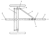
【解決手段】前部フレーム1に対して揺動する後部フレーム2の揺動軸の中心線上に、ステアリングシャフト4とナックル5とをつなぐタイロッド6のステアリングシャフト側ボールジョイント7の中心を合わせて設置し、ナックル側ボールジョイント8の中心を揺動軸の中心線と同一の高さになる様設置する。この様に設置する事により、揺動時に発生するタイロッドの左右運動を解消し、正立時と同様の操作特性を得られる。
【選択図】図6An object of the present invention is to eliminate a difference in left and right operation characteristics between swinging and erecting in a swinging three-wheeled bicycle having two front wheels and one rear wheel.
The center of the ball joint 7 on the steering shaft side of the tie rod 6 connecting the steering shaft 4 and the knuckle 5 is set on the center line of the swing shaft of the rear frame 2 swinging with respect to the front frame 1. Then, the center of the knuckle side ball joint 8 is installed so as to be the same height as the center line of the swing shaft. By installing in this way, the left and right movements of the tie rod that occur when swinging can be eliminated, and the same operating characteristics as when standing upright can be obtained.
[Selection] Figure 6
Description
本考案は、前二輪後一輪の揺動式三輪自転車に於いて、揺動時と正立時との左右操行特性の差を、解消する事を目的とする。 An object of the present invention is to eliminate the difference in left and right steering characteristics between swinging and upright in a swinging three-wheeled bicycle with one wheel at the front and one wheel at the rear.
従来揺動式三輪車は、前一輪後二輪式で操行は前一輪で行われ、左右操行特性には差は無かった。 Conventional swing type tricycles were operated with one front wheel and two rear wheels, and the front one wheel was operated, and there was no difference in the left and right steering characteristics.
しかしながら、前二輪後一輪式の三輪自転車で、後一輪が取り付けられた後部フレームを揺動させる構造とした場合、ハンドル操作をロッドで前二輪に伝えると、揺動時にロッドが不要な左右運動を発生し、正立時の左右操行特性との間に著しい差が生まれてしまう。 However, if the rear two-wheeled three-wheeled bicycle has a structure in which the rear frame to which the rear wheel is attached is rocked, if the handle operation is transmitted to the front two wheels with the rod, the left and right movements that do not require the rod during rocking are performed. And a significant difference is created between the left and right steering characteristics when standing upright.
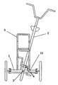
上記課題を解決する為には、前二輪が取り付けられた前部フレーム1に対して揺動する後部フレーム2の揺動軸3の中心線上に、ステアリングシャフト4とナックル5とをつなぐタイロッド6のステアリングシャフト側ボールジョイント7の中心を合わせて設置し、ナックル側ボールジョイント8の中心を揺動軸の中心線と同一の高さになる様設置する。この様に、揺動軸とステアリングシャフト側ボールジョイントとナックル側ボールジョイントを設置することにより、後部フレームを揺動させても揺動軸に対してのステアリング側ボールジョイントの位置は変わらず、ナックル側ボールジョイントとの距離が変わらない為、揺動によるタイロッドの左右運動が起こらなくなり、揺動時も正立時と同様の操作特性を得られる。 In order to solve the above problem, the
よって、本考案のステアリングシステムを使用する事により、運転者は後部フレームを揺動させながらスムーズなハンドル操作が可能となり安全運転に役立つ。 Therefore, by using the steering system of the present invention, the driver can operate the steering wheel smoothly while swinging the rear frame, which is useful for safe driving.
本考案に係る三輪自転車は、子供を安全に乗せる為の自転車を目的に開発され、子供を乗せる子供用シート9は、常に大地に接している前二輪が取り付けられた前部フレーム上にある為常に安定し、尚且つ運転者は通常の自転車同様、揺動させながら軽快な操行運転が可能となる。更に、揺動する速度を油圧式ダンパー10で制御する事により、旋回時の過度の倒れこみや路面の凹凸による姿勢変化を抑制し、安定した揺動が得られる。 The three-wheeled bicycle according to the present invention was developed for the purpose of safely riding a child, and the
1 前部フレーム
2 後部フレーム
3 揺動軸
4 ステアリングシャフト
5 ナックル
6 タイロッド
7 ステアリング側ボールジョイント
8 ナックル側ボールジョイント
9 子供用シート
10 油圧式ダンパーDESCRIPTION OF
Claims (2)
Publications (1)
| Publication Number | Publication Date |
|---|---|
| JP3147325U true JP3147325U (en) | 2008-12-25 |
Family
ID=
Cited By (2)
| Publication number | Priority date | Publication date | Assignee | Title |
|---|---|---|---|---|
| JP2013530079A (en) * | 2010-05-17 | 2013-07-25 | ラファル バドウエイル、 | Vehicle with adjustable track width |
| KR20150112448A (en) * | 2014-03-28 | 2015-10-07 | 유니이노 주식회사 | Walking type bike |
Cited By (2)
| Publication number | Priority date | Publication date | Assignee | Title |
|---|---|---|---|---|
| JP2013530079A (en) * | 2010-05-17 | 2013-07-25 | ラファル バドウエイル、 | Vehicle with adjustable track width |
| KR20150112448A (en) * | 2014-03-28 | 2015-10-07 | 유니이노 주식회사 | Walking type bike |
Similar Documents
| Publication | Publication Date | Title |
|---|---|---|
| CN101557977B (en) | three wheel vehicle | |
| US8925940B2 (en) | Tilting wheeled vehicle | |
| US20110031716A1 (en) | Tricycle and Steering Mechanism Therefor | |
| JP2006160254A (en) | Front wheel replacing method for three-wheeled vehicle | |
| JP2012056503A (en) | Vehicle configured to roll vehicle body | |
| US11407466B2 (en) | Tilting wheeled vehicle | |
| JP2014061870A (en) | Vehicle | |
| US20160304149A1 (en) | Tricycle with two riding modes | |
| JP4297967B1 (en) | Front motorcycle | |
| TWM441617U (en) | Tilt steering and suspension device of front two wheels for motorcycle | |
| JP2007186179A (en) | Steering mechanism by right and left independent wheels | |
| JP3147325U (en) | Swing type tricycle | |
| WO2014207489A4 (en) | Motor powered tricycle with a steering mode selcector | |
| JP2019031183A (en) | Suspension device, saddle-riding type vehicle including the same, snow vehicle and irregular ground traveling vehicle | |
| JP2017154685A (en) | vehicle | |
| TW201641345A (en) | Steering apparatus of shock absorbing mechanism | |
| JP2006248289A (en) | Front wheel device of two-wheeler | |
| JP5890722B2 (en) | Suspension device | |
| CN202863666U (en) | Four-wheel bike capable of enabling two users to ride side by side | |
| CN204821956U (en) | Whole suspension of dynamic balance vehicle | |
| CN205131485U (en) | Reverse tricycle and universal steering mechanism with universal steering mechanism | |
| CN110254589B (en) | High stability and handling motorcycle | |
| JP2006021734A (en) | Steering unit with reinforcing arm of motorcycle | |
| CN201842131U (en) | Steering control mechanism of tricycle | |
| CN216994690U (en) | Front-drive scooter based on reverse three-wheel structure |