JP3147520U - Plant container stand - Google Patents
Plant container stand Download PDFInfo
- Publication number
- JP3147520U JP3147520U JP2008007353U JP2008007353U JP3147520U JP 3147520 U JP3147520 U JP 3147520U JP 2008007353 U JP2008007353 U JP 2008007353U JP 2008007353 U JP2008007353 U JP 2008007353U JP 3147520 U JP3147520 U JP 3147520U
- Authority
- JP
- Japan
- Prior art keywords
- ring frame
- stand
- plant container
- lower ring
- upper ring
- Prior art date
- Legal status (The legal status is an assumption and is not a legal conclusion. Google has not performed a legal analysis and makes no representation as to the accuracy of the status listed.)
- Expired - Lifetime
Links
Images



Abstract
【課題】複数の植物容器用スタンドを平面方向に並べて配列する際に、従来よりも狭い配列スペースで並べることができ、またスタンドの内部空間部を有効利用することができる植物容器用スタンドを提供する。
【解決手段】植物容器を支持する上部リング枠2と、下部リング枠3とを連結杆4,4a,4bで連結した植物容器用スタンド1において,下部リング枠3に切欠部3を形成し、該下部リング枠3をC字状に形成する。切欠部3は、隣接する植物容器用スタンドの下部リング枠の一部が挿入できる大きさである。上部リング枠2に切欠部を形成することもできる。連結杆4,4a,4bは、上部リング枠2と下部リング枠3の空間部に植物容器等を出し入れ可能な間隔部を有するように配設している。
【選択図】図1Provided is a plant container stand that can be arranged in a narrower arrangement space than before when a plurality of plant container stands are arranged side by side in a plane direction, and the internal space of the stand can be used effectively. To do.
In a plant container stand 1 in which an upper ring frame 2 supporting a plant container and a lower ring frame 3 are connected by connecting rods 4, 4a and 4b, a notch 3 is formed in the lower ring frame 3, The lower ring frame 3 is formed in a C shape. The notch 3 has a size that allows a part of the lower ring frame of the adjacent plant container stand to be inserted. A notch can be formed in the upper ring frame 2. The connecting rods 4, 4 a, 4 b are arranged so as to have an interval part in which a plant container or the like can be taken in and out of the space part of the upper ring frame 2 and the lower ring frame 3.
[Selection] Figure 1
Description
本考案は、鉢、プランタ等の植物容器を載置するためのスタンドに関するものである。 The present invention relates to a stand for placing plant containers such as pots and planters.
鉢、プランタ等を載置するためのスタンドは従来から種々知られている。たとえば特許文献1には、リング状上部線材と、この上部線材よりも大径なリング状下部線材を4本の連結線材で連結し、その連結線材の上端を上部線材の外周側に溶接するとともに、その下端を下部線材の内周側に溶接したものが提案されている。このスタンドは、高さ方向に複数積み重ねても高さ方向のスペースがそれほど必要といないという利点がある。
Conventionally, various stands for placing bowls, planters and the like are known. For example, in
しかしながら、このような従来のスタンドは、複数のスタンドを平面方向に並べようとすると、隣り合うリング状下部線材が互いに干渉するため、広い配列スペースが必要になるという問題がある。また、4本の連結線材で等間隔に上部線材と下部線材を連結することにより強度保持を図っているため、連結線材同士の間隔が狭くなり、上部線材と下部線材間の空間部を有効に利用できないという問題もある。 However, such a conventional stand has a problem that when a plurality of stands are arranged in the plane direction, adjacent ring-shaped lower wire members interfere with each other, so that a wide arrangement space is required. In addition, since the strength is maintained by connecting the upper wire and the lower wire at equal intervals with the four connecting wires, the interval between the connected wires becomes narrower, and the space between the upper wire and the lower wire is made effective. There is also a problem that it cannot be used.
本考案は、このような問題を解決するために工夫されたものであり、複数の植物容器用スタンドを平面方向に並べて配列する際に、従来よりも狭いスペースで並べることができ、またスタンドの内部空間部を有効利用することができる植物容器用スタンドを提供することを目的とする。また本考案は、簡単な構成で安価に製造できる植物容器用スタンドを提供することを目的とする。 The present invention has been devised to solve such problems, and when arranging a plurality of plant container stands side by side in a plane direction, they can be arranged in a narrower space than before. It aims at providing the stand for plant containers which can utilize an internal space part effectively. Another object of the present invention is to provide a plant container stand that can be manufactured at a low cost with a simple configuration.
上記課題を解決するために、本考案に係る植物容器用スタンドの請求項1の考案は、植物容器を支持する上部リング枠と、下部リング枠とを連結杆で連結した植物容器用スタンドにおいて、
前記下部リング枠に切欠部を形成し、該下部リング枠をC字状に形成したことを特徴とする。
In order to solve the above problems, the plant container stand according to
A cutout portion is formed in the lower ring frame, and the lower ring frame is formed in a C shape.
植物容器とは、花、盆栽、観葉植物等を植え又は飾るためのプランタ、鉢、花瓶その他の容器であり、さらにはこれらを載置ないし収容するための受皿、受台、カップ等も含まれる。植物容器の形状は特に限定されるものではなく、その植物容器の形状に対応させて上部リング枠の形状を真円、楕円、多角形等のリング形状に形成することができる。上下部リング枠は同径でもよいが、下部リング枠を上部リング枠の外径よりも大径にするとスタンドの安定性が良くなる。 Plant containers are planters, pots, vases and other containers for planting or decorating flowers, bonsai, foliage plants, etc., and also include saucers, cradles, cups, etc. for mounting or housing these. . The shape of the plant container is not particularly limited, and the shape of the upper ring frame can be formed into a ring shape such as a perfect circle, an ellipse, or a polygon according to the shape of the plant container. The upper and lower ring frames may have the same diameter, but if the lower ring frame is made larger than the outer diameter of the upper ring frame, the stability of the stand is improved.
下部リング枠の切欠部の間隔は、ここでは任意であり、一緒に並べるスタンド、植物容器等の大きさや形状等に応じて選定される。また、ここでの連結杆による連結位置、本数等は任意である。連結杆は、上下部リング枠と一体成形、溶接等の固定手段により連結される。なお、上下部リング枠と連結杆は、スチール、強化プラスチック等により作製される。 The interval between the cutouts of the lower ring frame is arbitrary here, and is selected according to the size, shape, etc. of the stand, plant container, etc. arranged together. Further, the connecting position, the number, etc. of the connecting rods are arbitrary. The connecting rod is connected to the upper and lower ring frames by fixing means such as integral molding and welding. The upper and lower ring frames and the connecting rod are made of steel, reinforced plastic or the like.
このような植物容器用スタンドは、下部リング枠を下にして立脚させ、上部リング枠に植物容器を支持することができる。また、たとえば高さの異なる同形スタンドを平面方向に複数並べて配列する場合、隣接する一方の下部リング枠の一部を他方の下部リング枠の切欠部に装入した状態で並べることができ、平面方向の配列スペースを狭くすることができる。 Such a stand for plant containers can be made to stand with the lower ring frame down and can support the plant container on the upper ring frame. In addition, for example, when arranging a plurality of the same-shaped stands having different heights in the plane direction, a part of one lower ring frame adjacent to each other can be arranged in a state of being inserted into the cutout part of the other lower ring frame. The arrangement space in the direction can be narrowed.
さらに、隣接するスタンドの切欠部の位置を適当な方向に向けることにより、スタンドの設置場所に応じて、たとえばサークル状、蛇行状等のように多様な配列形態を採用することができる。なお、同形スタンドを並べる場合に限らず、別の植木鉢、プランタ等を並べて置くときも、その下端縁部を下部リング枠切欠部に装入することにより配列スペースを狭くすることができる。 Furthermore, by arranging the positions of the notches of the adjacent stands in an appropriate direction, various arrangement forms such as a circle shape and a meandering shape can be adopted according to the installation location of the stand. It should be noted that the arrangement space can be narrowed by inserting the lower edge of the lower ring frame notch into the lower ring frame not only when the same-shaped stands are arranged, but also when another flower pot, planter, or the like is placed side by side.
また請求項2の考案は、前記下部リング枠の切欠部は、隣接する植物容器用スタンドの下部リング枠の一部が挿入できる大きさの切欠部であることを特徴とする。
The invention of
ここで隣接する別の植物容器用スタンドは特に限定されるものではなく、隣接するスタンドの下部リング枠は同径でも異径でもよい。下部リング枠の切欠部は、その間隔が大きすぎるとスタンド全体の安定性が低下するため、隣接する植物容器用スタンドとの取り合わせを考慮して適切な切欠部の間隔を選定する。このような考案によれば、高さの異なる同形の複数の植物容器用スタンドの下部リング枠を、部分的に切欠部に装入させるような状態で平面方向に並べて配列することができ、統一性のあるディスプレイを実現できる。 Here, another plant container stand that is adjacent is not particularly limited, and the lower ring frame of the adjacent stand may be the same diameter or different diameter. If the notch portion of the lower ring frame is too large, the stability of the entire stand is lowered. Therefore, an appropriate notch interval is selected in consideration of the combination with the adjacent plant container stand. According to such a device, the lower ring frames of a plurality of plant container stands having the same shape with different heights can be arranged side by side in the plane direction in a state in which they are partially inserted into the cutout portions. A realistic display can be realized.
また請求項3の考案は、前記上部リング枠に切欠部を形成し、該上部リング枠をC字状に形成したことを特徴とする。
The invention of
このようにすれば、たとえば隣接する同形のスタンドの上部リング枠の一部を他方の上部リング枠の切欠部に装入することができるため、同じ高さのスタンドを平面方向に並べて配列する際の省スペース化を図ることができる。 In this way, for example, a part of the upper ring frame of the adjacent same-shaped stand can be inserted into the cutout portion of the other upper ring frame, so that when the stands of the same height are arranged side by side in the plane direction, Can be saved.
また請求項4の考案は、前記上部リング枠の切欠部は、隣接する植物容器用スタンドの上部リング枠の一部が挿入できる大きさの切欠部であることを特徴とする。
The invention of
隣接する別の植物容器用スタンドは特に限定されるものではなく、隣接するスタンドの上部リング枠は同径でも異径でもよい。上部リング枠の切欠部は、その間隔が大きすぎると植物容器を安定して支持できなくなるため、隣接する植物容器用スタンドとの取り合わせを考慮して適切な切欠部の間隔を選定する。このような考案によれば、同じ高さの同形の複数の植物容器用スタンドの上下部リング枠を、部分的に切欠部に装入させるような状態で平面方向に並べて配列することができる。 The adjacent stand for another plant container is not particularly limited, and the upper ring frame of the adjacent stand may have the same diameter or a different diameter. If the notch portion of the upper ring frame is too large, the plant container cannot be stably supported. Therefore, an appropriate notch interval is selected in consideration of the arrangement with the adjacent plant container stand. According to such a device, the upper and lower ring frames of a plurality of plant container stands having the same shape and having the same height can be arranged side by side in the plane direction so as to be partially inserted into the notches.
また請求項5の考案は、前記連結杆を、前記上部リング枠と前記下部リング枠の空間部に植物容器を出し入れ可能な間隔を有するように複数配設したことを特徴とする。 Further, the invention of claim 5 is characterized in that a plurality of the connecting rods are arranged so as to have a space in which a plant container can be taken in and out of the space between the upper ring frame and the lower ring frame.
このようにすると、上部リング枠と下部リング枠の空間部に別の植物容器等を置くことができ、その空間部を有効利用することができる。 If it does in this way, another plant container etc. can be put in the space part of an upper ring frame and a lower ring frame, and the space part can be used effectively.
また請求項6の考案は、前記連結杆を、前記上部リング枠と前記下部リング枠との周方向に間隔をあけて3本配設したことを特徴とする。 The invention of claim 6 is characterized in that three connecting rods are arranged at intervals in the circumferential direction of the upper ring frame and the lower ring frame.
このようにすると、上部リング枠と下部リング枠を最小本数で連結することにより、スタンド全体の強度を保持することができ、しかも連結杆同士の間隔を広くとることができるため、上部リング枠と下部リング枠の空間部へ、別の植物容器等の出し入れを容易に行うこともできる。 In this way, by connecting the upper ring frame and the lower ring frame with the minimum number, the strength of the entire stand can be maintained, and the interval between the connecting rods can be widened. Another plant container or the like can be easily put in and out of the space of the lower ring frame.
また請求項7の考案は、前記連結杆を、前記上部リング枠と前記下部リング枠との周方向に、不均等な間隔で配設したことを特徴とする。 The invention of claim 7 is characterized in that the connecting rods are arranged at uneven intervals in the circumferential direction of the upper ring frame and the lower ring frame.
このようにすると、下部リング枠及び/又は上部リング枠に、適切な間隔の切欠部を形成することができ、しかも、連結杆の間隔が広い部分から上部リング枠と下部リング枠の空間部へ、別の植物容器等の出し入れを容易に行うことができる。 In this way, it is possible to form notched portions with appropriate intervals in the lower ring frame and / or the upper ring frame, and from the portion where the distance between the connecting rods is wide to the space portion of the upper ring frame and the lower ring frame. It is possible to easily take in and out other plant containers and the like.
また請求項8の考案は、前記連結杆を、前記下部リング枠の切欠部の両端部と、該切欠部両端部を一辺とする正三角形又は二等辺三角形の頂点部に配設したことを特徴とする。 The invention of claim 8 is characterized in that the connecting rods are arranged at both ends of the cutout portion of the lower ring frame and at the apex of an equilateral triangle or an isosceles triangle having both sides of the cutout portion as one side. And
このようにすると、スタンド全体が安定する位置に連結杆を配設することができ、しかも下部リング枠切欠部を適切な間隔とし、上部リング枠と下部リング枠の空間部へ、別の植物容器等の出し入れするための連結杆の間隔を確保することもできる。 In this way, the connecting rod can be disposed at a position where the entire stand is stable, and the lower ring frame notch is set at an appropriate interval, and another plant container is moved to the space between the upper ring frame and the lower ring frame. It is also possible to secure a space between the connecting rods for taking in and out the like.
また請求項9の考案は、前記上部リング枠に植物容器の受皿を載置したことを特徴とする。 The invention of claim 9 is characterized in that a tray for a plant container is placed on the upper ring frame.
このようにすると、受皿に植木鉢等の植物容器を載せることができ、その植物容器に含まれる水が受皿に溜るため、床面等に落下することはない。 If it does in this way, plant containers, such as a flower pot, can be mounted in a saucer, and since the water contained in the plant container accumulates in a saucer, it does not fall on a floor etc.
本考案の植物容器用スタンドによれば、スタンドを平面方向に複数並べて配列する際に、従来よりも狭いスペースで並べることができ、またスタンドの内部空間部を有効利用することができる。さらに本考案によれば、構成が簡単で安価に製造できる等の効果が得られる。 According to the plant container stand of the present invention, when a plurality of stands are arranged side by side in the plane direction, they can be arranged in a narrower space than before, and the internal space of the stand can be used effectively. Furthermore, according to the present invention, it is possible to obtain an effect that the structure is simple and can be manufactured at low cost.
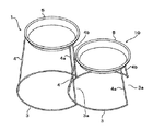
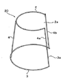
以下、本考案の実施形態を添付図面に従って説明する。図1は本考案をボールプランタ用のスタンドに適用した場合の全体斜視図、図2の(a)はその平面図、(b)は側面図を示している。 Hereinafter, embodiments of the present invention will be described with reference to the accompanying drawings. FIG. 1 is an overall perspective view when the present invention is applied to a stand for a ball planter, FIG. 2 (a) is a plan view thereof, and FIG. 1 (b) is a side view thereof.
スタンド1は、上部リング枠2と、下部リング枠3と、これらを連結する連結杆4,4a,4bからなっている。下部リング枠3は、上部リング枠2よりも大径であり、その一部に切欠部3aが形成され、全体がC字状となっている。上部リング枠2は、プランタ等を載置できる内径を有しており、下部リング枠3は上部リング枠2に載置したプランタを安定して支持できる大きさとする。
The
連結杆4,4a,4bは、ここでは上部リング枠2と下部リング枠3の周方向に間隔をあけて3本配設されている。具体的には、図2(a)に示すように、下部リング切欠部3aの両端部に固定された連結杆4a,4bと、この切欠部3aの両端部を結ぶ線を一辺とする仮想の二等辺三角形6の頂点部に固定された連結杆4からなっている。
Here, three connecting
このように配設された連結杆は、連結杆4ー4a及び4ー4bの間隔が連結杆4aー4bの間隔よりも大きくなっており、不均等な間隔で配設されている。
The connecting rods arranged in this way are arranged at unequal intervals because the interval between the connecting rods 4-4a and 4-4b is larger than the interval between the connecting
また、図1に示すように、連結杆4,4a,4bの上端は、上部リング枠2の外周面側に固定され、その下端は下部リング枠3の内周面側に固定されており、これにより同形のスタンド1を複数積み重ねる場合、高さ方向の省スペース化が図られる(上記特許文献1を参照)。なお、スタンド1はここではスチール線材で製作されており、上下部リング枠2,3と連結杆4,4a,4bは溶接により固定されている。
Further, as shown in FIG. 1, the upper ends of the connecting
図3及び図4に示すスタンド10は、連結杆4,4a,4bの長さを図1より短くし、上述のスタンド1よりも高さを低くしたものであり、その他の構成は図1と同じである。
The
つぎに、本考案の植物容器用スタンドの使用例を説明する。まず、スタンド1,10を別々で使用する場合は、植物の種類、配列場所等に応じた最適な高さのスタンドを選択し、各上部リング枠2に植物を植えたボールプランタ等(図示せず)を載置し、室内、庭等に配置することができる。
Below, the usage example of the stand for plant containers of this invention is demonstrated. First, when the
また、両方のスタンド1,10並べて配列するときは、図5に示すように、高さの高いスタンド1の下部リング枠3の切欠部3aに、高さの低いスタンド10の下部リング枠3の一部(切欠部3aが形成されていない部分)を装入した状態で配列する。スタンド10の切欠部3aにも同じようにして別のスタンド(図示せず)を配列することができる。この場合、スタンド10をわずかに回して切欠部3aの向きを変えることにより、直線的な配列のみならず、全体がサークル状、蛇行状等になるような配列とすることもできる。
When both the
このように、スタンド10の下部リング枠3が、スタンド1の下部リング枠3の内方に装入した分、両スタンド1,10を近づけて並べることができ、複数のスタンドを平面方向に並べて配列するときの省スペース化を図ることができる。また高さの異なるスタンド1,10を段状に並べることができるため、植物容器を載置したときの見栄えも良くなる。
In this way, the
また、スタンド1,10は、連結杆4−4aと4−4bの間隔が広いため、下部リング枠3と上部リング枠2の空間部に、別のプランタ、鉢等を容易に出し入れすることができる。
Moreover, since the space | interval of the connecting rods 4-4a and 4-4b is wide in the
なお、未使用のスタンド1,10は高さ方向に重ねて保管することができるが、各スタンド1,10の連結杆4,4a,4bの上端を上部リング枠2の外周面側に固定し、その下端を下部リング枠3の内周面側に固定しているため、特に同じ高さのスタンド同士を積み重ねる際に、高さ方向のスペースをさほど必要としなくなる。
Although the
上述の実施形態ではスタンド1,10の上部リング枠2にプランタ等を直接載置する場合を例にとって説明したが、図6に示すように、上部リング枠2に受皿5を載置し、この受皿5にプランタ、鉢等を載置することもできる。このようにすれば、吸水時にプランタ、鉢等に含まれる水が受皿5に溜まるため、床面等を汚すことはない。また、上部リング枠2よりも外径が小さなプランタ、鉢等を受皿5に載置して飾ることもできる。
In the above-described embodiment, the case where a planter or the like is directly placed on the
図7及び図8は、本考案の別の実施形態であり、図7は高さの高いスタンド20、図8は高さの低いスタンド21を示している。これらスタンド20,21は、下部リング枠3の切欠部3aに対応させて上部リング枠2にも切欠部2aが形成されている部分が相違するだけで、その他の構成は上記図1ないし図6で示した実施態様とである。
7 and 8 show another embodiment of the present invention. FIG. 7 shows a
このような実施形態のスタンド20,21は、別々に使用することもできるが、同じ高さのスタンド20又は21を並べて配列するときに便利である。即ち、上部リング枠2にも切欠部2aが形成されているため、スタンド20又は21の下部リング枠切欠部3aと上部リング枠切欠部2aに、隣り合うスタンドの下部リング枠3と上部リング枠2の一部を装入させた状態で配列することができる。このため同高のスタンド20又は21を平面方向に並べて配列するときの省スペース化を図ることができる。
Although the
高さの異なるスタンド20,21の組み合わせ、又は上記スタンド1,10との組み合わせも自在である。さらに、これらスタンド20,21の上部リング枠2,2に、図6に示すような受皿5を載置し、この受皿5にプランタ、鉢等を載置してもよいことは言うまでもない。
A combination of the
上述の実施態様は本考案の一例を示したものであり、プランタの形状は図示したものに限定されることはなく、五角形、六角形、八角形等の多角形のリンク形状であってもよい。また、上下リング部2,3の切欠部2a,3aの間隔は、スタンドの強度、安定性等を考慮して変更することができ、これに応じて連結杆4,4a,4bによる連結位置、連結数等を変更することができる。さらに、ここでは材料としてスチール線材を使用しているが、さらに補強用の線材を設けたり、帯状のスチール材等を使用することもできる。その他、本考案の趣旨にしたがって上記各実施態様を変更することができる。
The above-described embodiment shows an example of the present invention, and the shape of the planter is not limited to the illustrated shape, and may be a polygonal link shape such as a pentagon, a hexagon, and an octagon. . Further, the interval between the
1,10,20,21はスタンド
2は上部リング枠
2aは上部リング枠切欠部
3は下部リング枠
3aは下部リング枠切欠部
4,4a,4bは連結杆
5は受皿
6は仮想三角形
1, 10, 20, and 21 are
Claims (9)
前記下部リング枠に切欠部を形成し、該下部リング枠をC字状に形成したことを特徴とする植物容器用スタンド。 In the plant container stand in which the upper ring frame supporting the plant container and the lower ring frame are connected by a connecting rod,
A stand for a plant container, wherein a cutout portion is formed in the lower ring frame, and the lower ring frame is formed in a C shape.
Publications (1)
| Publication Number | Publication Date |
|---|---|
| JP3147520U true JP3147520U (en) | 2009-01-08 |
Family
ID=
Similar Documents
| Publication | Publication Date | Title |
|---|---|---|
| US6862843B2 (en) | Umbrella planter with a snap-on base | |
| JP3225207U (en) | Potted Phalaenopsis orchid aggregate | |
| KR200466623Y1 (en) | Prefabricated Flowerpot | |
| KR101313057B1 (en) | Crops Supporting Equipment | |
| KR101201355B1 (en) | Flowerpot for gardening, and gardening structure using thereof | |
| JP3148053U (en) | Plant support device and plant cultivation shelf assembly set | |
| JP2009516564A (en) | Flower arrangements for ikebana and vegetation | |
| JP3172204U (en) | Apparel | |
| JP5016149B1 (en) | Exhibition stand | |
| JP2014050376A (en) | Molding product holding pot for group planting | |
| KR100905800B1 (en) | Fruit trees for display using connect frame | |
| JP7695733B1 (en) | Double-sided pot stand | |
| JP7748754B2 (en) | Cultivation container stand | |
| KR101914112B1 (en) | Flowerpot | |
| KR200232459Y1 (en) | Flowerpot support | |
| KR20070119940A (en) | Flower pots | |
| JP2007244219A (en) | Method for manufacturing pots and pots planted with plants | |
| KR200427157Y1 (en) | Flower pot holder | |
| JP3234740U (en) | Pot stand | |
| JP3805284B2 (en) | Container support structure | |
| JP3094280U (en) | Structure of climbing plants and general plant shelves | |
| JP3089728U (en) | Flowerpot multi-tray | |
| KR200227649Y1 (en) | Flowerpot supporter | |
| WO2014178786A1 (en) | Arrangement for supporting a plant | |
| KR101146245B1 (en) | A flowerpot for flower tower |