JP3147744U - Product divider - Google Patents
Product divider Download PDFInfo
- Publication number
- JP3147744U JP3147744U JP2008007625U JP2008007625U JP3147744U JP 3147744 U JP3147744 U JP 3147744U JP 2008007625 U JP2008007625 U JP 2008007625U JP 2008007625 U JP2008007625 U JP 2008007625U JP 3147744 U JP3147744 U JP 3147744U
- Authority
- JP
- Japan
- Prior art keywords
- partition plate
- stopper
- product
- substrate
- end portion
- Prior art date
- Legal status (The legal status is an assumption and is not a legal conclusion. Google has not performed a legal analysis and makes no representation as to the accuracy of the status listed.)
- Expired - Lifetime
Links
- 238000005192 partition Methods 0.000 claims abstract description 88
- 239000000758 substrate Substances 0.000 claims abstract description 65
- 230000000630 rising effect Effects 0.000 claims abstract description 6
- 239000002184 metal Substances 0.000 claims description 5
- 238000000638 solvent extraction Methods 0.000 description 4
- 239000011347 resin Substances 0.000 description 3
- 229920005989 resin Polymers 0.000 description 3
- 239000003814 drug Substances 0.000 description 2
- 229940079593 drug Drugs 0.000 description 2
- 238000003780 insertion Methods 0.000 description 2
- 230000037431 insertion Effects 0.000 description 2
- BGPVFRJUHWVFKM-UHFFFAOYSA-N N1=C2C=CC=CC2=[N+]([O-])C1(CC1)CCC21N=C1C=CC=CC1=[N+]2[O-] Chemical compound N1=C2C=CC=CC2=[N+]([O-])C1(CC1)CCC21N=C1C=CC=CC1=[N+]2[O-] BGPVFRJUHWVFKM-UHFFFAOYSA-N 0.000 description 1
- 238000010586 diagram Methods 0.000 description 1
- 230000000694 effects Effects 0.000 description 1
- 238000000034 method Methods 0.000 description 1
Images



Abstract
【課題】プライスカードレールに係合可能な傾斜棚専用の商品仕切板を提供する。
【解決手段】長尺で平板状の基板部2と、基端部2の裏面に装着されたマグネット3と、基板部2上に基板部2の面と直交する上方に向けて連設した長尺で平板状の仕切板本体4と、仕切板本体4の前端部分に連設した、商品陳列棚の前面側に係止されたプライスカードレールの係合凹部に係合される係合部502を下端部近傍に有するストッパー部5を具備し、仕切板本体4は、基板部2に連設される下端部401の前端部分から斜め前方に向けてテーパー状に立ち上がったテーパー部を有する。該テーパー部の先端部分から上方に立ち上がったストッパー連設部にストッパー部5を連設し、係合部502と基板部2の前端部分との間に空間6を確保した。
【選択図】図1A product partition plate dedicated to an inclined shelf that can be engaged with a price card rail is provided.
SOLUTION: A long and flat substrate portion 2, a magnet 3 mounted on the back surface of a base end portion 2, and a length provided on the substrate portion 2 so as to extend upward perpendicular to the surface of the substrate portion 2. A flat plate-like partition plate body 4 and an engagement portion 502 that is connected to the engagement concave portion of the price card rail that is connected to the front side of the merchandise display shelf and that is connected to the front end portion of the partition plate body 4. The partition plate body 4 has a taper portion that rises in a tapered shape from the front end portion of the lower end portion 401 connected to the base plate portion 2 obliquely forward. The stopper portion 5 was continuously provided at the stopper continuous portion rising upward from the tip portion of the taper portion, and a space 6 was secured between the engaging portion 502 and the front end portion of the substrate portion 2.
[Selection] Figure 1
Description
本考案は、スーパーマーケットやドラッグストアにおいて、前方に行くに従って下方側に傾斜する金属製の商品陳列棚(以下「傾斜棚」という。)の上に陳列された商品を仕切るために、傾斜棚上に傾斜棚の前後方向に向いて載置されて用いられる、裏面にマグネットを備えた商品仕切板に係り、より詳しくは、商品を傾斜棚上に傾斜棚と並行に配置しつつ、傾斜棚の前面側に係止されたプライスカードレールに係合可能とした商品仕切板に関する。 In the present invention, in a supermarket or a drug store, a product displayed on a metal product display shelf (hereinafter referred to as an “inclined shelf”) that is inclined downward as it goes forward is partitioned on an inclined shelf. The present invention relates to a product partition plate having a magnet on the back surface, which is used by being placed in the front-rear direction of the inclined shelf, and more specifically, the front of the inclined shelf while placing the product on the inclined shelf in parallel with the inclined shelf. The present invention relates to a product partition plate which can be engaged with a price card rail locked to the side.
一般的にスーパーマーケットやドラッグストアにおいては、特に文房具等の展示に際しては、手前側に行くに従って下側に傾斜した金属製の商品陳列棚である傾斜棚が用いられることがあり、更に、これらの傾斜棚に陳列された商品を種類別等に区分けするために、裏面にマグネットを備えた、傾斜棚専用の商品仕切板が用いられている。 In general, in supermarkets and drug stores, especially when displaying stationery, inclined shelf, which is a metal product display shelf that is inclined downward as it goes to the near side, may be used. In order to classify the products displayed on the shelf according to type or the like, a product partition plate dedicated to an inclined shelf having a magnet on the back surface is used.
ここで、前述のような傾斜棚専用の商品仕切板の従来例について説明すると、図8は従来の傾斜棚専用の商品仕切板を説明するための斜視図であり、図において31が、従来の傾斜棚専用の商品仕切板である。そして、この従来の商品仕切板31は、裏面にマグネット35が装着された長尺な平板状の基板部32を有している。
Here, a conventional example of a product partition plate dedicated to an inclined shelf as described above will be described. FIG. 8 is a perspective view for explaining a conventional product partition plate dedicated to an inclined shelf. In FIG. This is a product divider dedicated to inclined shelves. The conventional
そして、この基板部32の長手方向に沿った一側には、前記基板部32の長手方向寸法とほぼ同一寸法の長さを有する、長尺で平板状の商品仕切部33が、前記基板部32の面に対して直交する方向に連設されており、これにより、基板部32と商品仕切部33とで、正面視野で略L字状に構成されている。
On one side along the longitudinal direction of the
更に、前記基板部32の長手方向に向いた前端には、前記商品仕切部33の高さ寸法とほぼ同一の高さ寸法を有する平板状のストッパー部34が、前記基板部32の面に対して直交する方向に連設されており、これにより、基板部32とストッパー部34とで、側面視野で略L字状とされるとともに、ストッパー部34は前記商品仕切部33の端部にも、前記商品仕切部33の面に対して直交する方向に連結されている。
Furthermore, a
そして、これを使用する場合には、傾斜棚の前後方向と基板部32の長手方向が並行になるようにして、基板部32を傾斜棚上に載置するのみでよく、それにより、マグネット35の磁力で商品仕切り板31が傾斜棚上に装着され、商品仕切部33によって傾斜棚上の商品を仕切ることが可能となる。
When this is used, it is only necessary to place the
ところで、従来から、商品陳列棚の前面側にプライスカードレールを装着することが行われているが、傾斜棚においてもプライスカードレールを装着することがあるため、前述の商品仕切板をプライスカードレールに装着できれば都合がよい。 By the way, the price card rail has been conventionally attached to the front side of the product display shelf. However, since the price card rail may also be attached to the inclined shelf, the above-mentioned product divider is used as the price card rail. It is convenient if it can be attached to.
しかし、前述の商品仕切板をプライスカードレールに装着する場合には、ストッパー部34をプライスカードレールに係合する必要があるが、前述したように、傾斜棚専用の従来の商品仕切板31では、図8からも明らかなように、ストッパー部34の下端部が基板部32に連設されているため、これをプライスカードレールに装着することは不可能である。
However, when the above-mentioned product partition plate is attached to the price card rail, it is necessary to engage the
この点、ストッパー部の下端部よりも上方において基板部とストッパー部を連結する方法が採用されており、これによれば、ストッパー部の下端部をプライスカードレールに係合することが可能だが、かかる場合には、基板部の前端側が上方に傾斜してしまうために、傾斜棚と平行な状態で商品を傾斜棚に載置することができない、という問題点が考えられる。
そこで、本考案は、プライスカードレールに係合することが可能であるとともに、その際に傾斜棚上の商品を傾斜棚の面と並行に載置することが可能な傾斜棚専用の商品仕切板を提供することを課題としている。 Therefore, the present invention can be engaged with the price card rail, and at that time, the product divider for exclusive use of the inclined shelf that can place the product on the inclined shelf in parallel with the surface of the inclined shelf. It is an issue to provide.
本考案の商品仕切板は、前方に行くに従って下方側に傾斜する金属製の商品陳列棚板上に配置した商品を仕切るために、商品陳列棚上に商品陳列棚の前後方向に向いて載置されて用いられる商品仕切板であって、
長尺で平板状の基板部と、該基端部の裏面に装着されたマグネットと、前記基板部上に基板部の面と直交する上方に向けて連設した長尺で平板状の仕切板本体と、該仕切板本体の前端部分に連設した、前記商品陳列棚の前面側に係止されたプライスカードレールの係合凹部に係合される係合部を下端部近傍に有するストッパー部と、を具備し、
前記仕切板本体は、前記基板部に連設される下端部の前端部分から斜め前方に向けてテーパー状に立ち上がったテーパー部を有するとともに、該テーパー部の先端部分から上方に立ち上がったストッパー連設部を有し、該ストッパー連設部に前記ストッパー部を連設し、前記係合部と前記基板部の前端部分との間に空間を確保したことを特徴としている。
The product partition plate of the present invention is placed on the product display shelf in the front-rear direction of the product display shelf in order to partition the product placed on the metal product display shelf that inclines downward as it goes forward Product partition plate used,
A long, flat-plate-shaped partition plate, a magnet mounted on the back surface of the base end portion, and a long, flat-plate-shaped partition plate provided on the substrate portion so as to extend upward perpendicular to the surface of the substrate portion. A stopper portion having an engagement portion in the vicinity of the lower end portion, which is engaged with an engagement concave portion of a price card rail, which is connected to the front side of the product display shelf, which is connected to the main body and the front end portion of the partition plate body And comprising
The partition plate main body has a tapered portion that rises in a tapered shape from a front end portion of a lower end portion that is provided continuously with the substrate portion, and a stopper that is provided upward from a tip portion of the tapered portion. And the stopper portion is connected to the stopper connecting portion, and a space is secured between the engaging portion and the front end portion of the substrate portion.
本考案の商品仕切板では、長尺で平板状の基板部と、この基端部の裏面に装着されたマグネットと、基板部上に基板部の面と直交する上方に向けて連設した長尺で平板状の仕切板本体と、仕切板本体の前端部に連設した、プライスカードレールの係合凹部に係合される係合部を有するストッパー部とで構成されて、商品陳列棚上に商品陳列棚の前後方向に向いて載置される商品仕切板を前提とし、ストッパー部における係合部と、商品陳列棚上に載置される基板部の前端部分との間に空間を確保したことを特徴としている。 In the product partition plate of the present invention, a long and flat substrate portion, a magnet mounted on the back surface of the base end portion, and a length continuously provided on the substrate portion upwardly perpendicular to the surface of the substrate portion. A partition plate body having a flat plate shape, and a stopper portion having an engaging portion that engages with an engagement recess of the price card rail, which is provided continuously with the front end portion of the partition plate body. Assuming a product divider placed on the product display shelf in the front-rear direction, a space is secured between the engaging portion of the stopper and the front end portion of the substrate unit placed on the product display shelf. It is characterized by that.
そのため、本考案の商品仕切板では、基板部に邪魔されることなく、係合部をプライスカードレールに係合することが可能であるとともに、基板部の前端側が上方に傾斜することがなく、商品を陳列棚の面と並行に陳列棚上に載置することが可能である。 Therefore, in the product partition plate of the present invention, the engagement portion can be engaged with the price card rail without being obstructed by the substrate portion, and the front end side of the substrate portion is not inclined upward, It is possible to place the product on the display shelf in parallel with the surface of the display shelf.
本考案の商品仕切板では、前記商品陳列棚上に棚板の前後方向に向いて載置される長尺で平板状の基板部を有しており、この基端部の裏面にはマグネットが装着されている。 In the product partition plate of the present invention, the product display shelf has a long and flat substrate portion placed on the product display shelf in the front-rear direction of the shelf plate, and a magnet is provided on the back surface of the base end portion. It is installed.
また、基板部上には、基板部の面と直交する上方に向けて、長尺で平板状の仕切板本体が連設されており、仕切板本体の前端部には、商品陳列棚の前面側に係止されたプライスカードレールの係合凹部に係合される係合部を下端部近傍に有するストッパー部が連設されている。 In addition, a long and flat partition plate main body is continuously provided on the substrate portion in an upward direction perpendicular to the surface of the substrate portion. The front end portion of the partition plate main body has a front surface of a product display shelf. The stopper part which has the engaging part engaged by the engaging recessed part of the price card rail latched by the side in the lower end vicinity is provided in a row.
そして、前記仕切板本体は、前記基板部に連設される下端部の前端部分から斜め前方に向けてテーパー状に立ち上がったテーパー部を有するとともに、テーパー部の先端部分から上方に立ち上がったストッパー連設部を有しており、このストッパー連設部に前記ストッパー部を連設し、これにより、ストッパー部における係合部と前記基板部の前端部分との間に空間を確保している。 The partition plate body has a tapered portion that rises in a tapered manner from the front end portion of the lower end portion provided continuously to the substrate portion toward the front of the stopper, and the stopper plate that rises upward from the tip portion of the tapered portion. The stopper portion is connected to the stopper continuous portion, thereby securing a space between the engaging portion of the stopper portion and the front end portion of the substrate portion.
ここで、仕切板本体とストッパー部との連設の形態は特に限定されないが、例えば、平面視野において、仕切板本体とストッパー部とで略L字状あるいは略逆L字状になるような配置で仕切板本体にストッパー部を連設する形態、平面視野において仕切板本体とストッパー部とで略逆T字状になるような配置で仕切板本体の前端部にストッパー部を連設する形態が考えられる。 Here, the form in which the partition plate main body and the stopper portion are continuously provided is not particularly limited. For example, in a planar view, the partition plate main body and the stopper portion are arranged in an approximately L shape or a substantially inverted L shape. In the configuration in which the stopper portion is continuously connected to the partition plate body, the stopper portion is continuously connected to the front end portion of the partition plate body in a plane view so that the partition plate body and the stopper portion are arranged in a substantially inverted T shape. Conceivable.
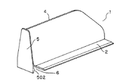
本考案の商品仕切板の実施例について図面を参照して説明すると、図1乃至図5は、本実施例の商品仕切板を説明するための図であり、図1は斜め手前側から見た斜視図、図2は斜め後方側から見た斜視図、図3は右側面図、図4は平面図、図5は正面図であり、図において1が本実施例の商品仕切板である。 An embodiment of the product partition plate of the present invention will be described with reference to the drawings. FIGS. 1 to 5 are diagrams for explaining the product partition plate of the present embodiment, and FIG. 1 is viewed from an oblique front side. A perspective view, FIG. 2 is a perspective view seen from an oblique rear side, FIG. 3 is a right side view, FIG. 4 is a plan view, and FIG. 5 is a front view. In the figure, 1 is a product partition plate of this embodiment.
そして、本実施例における商品仕切板1は、傾斜棚上に載置される基板部を有している。即ち、図において2が基板部であり、本実施例においてこの基板部2は、透明あるいは半透明な樹脂製の長尺の平板状としており、長手方向の寸法は、約125mm、あるいは約175mmの長さとし、また幅方向の寸法は約25mmとし、使用に際しては、長手方向が傾斜棚の前後方向に向くようにして、傾斜棚上に載置される。
And the
また、前記基板部2の裏面にはマグネット3が装着されており、これにより、マグネットの磁力により、基板部2を傾斜棚上に固定可能としている。
Further, a
次に、前記基板部2の長手方向に沿った1側には仕切板本体が上方に向けて連設されている。即ち、図において4が仕切板本体であり、本実施例において前記仕切板本体4は、透明あるいは半透明な樹脂製の長尺の平板状としており、高さ寸法は、約73mm、あるいは約88mmとし、また、下端部401の寸法は、前記基板部2の長手方向の寸法とほぼ同一寸法としている。そして、仕切板本体4の面が前記基板部2の面と直交する形態において、下端部401の全域を前記基板部2の長手方向に沿った一側に、上方に向けて連設し、これにより、長手方向に見た断面形状が、基板部2と仕切板本体4でL字状になるようにしている。
Next, a partition plate main body is continuously provided on one side along the longitudinal direction of the
そして、前記仕切板本体4の前端部には、商品陳列棚上に配置した商品が陳列棚の傾斜に沿って手前側にずり落ちてしまうことを防止するためのストッパーが連設されている。
The front end of the
ここで、前記ストッパーについて説明すると、図において5が本実施例におけるストッパーであり、本実施例において前記ストッパー5は、透明あるいは半透明な樹脂製の平板状としたストッパー本体501を有しており、このストッパー本体501は、前記仕切板本体4の高さ方向の寸法とほぼ同一の高さ寸法とし、高さ方向に沿った一側を、前記仕切板本体4の前端部に、仕切板本体4の面とストッパー本体501の面が直交するような配置で連設しており、平面視野において仕切板本体4とストッパー本体501で略L字状になるようにしている。
Here, the stopper will be described. In the figure,
そして、前記ストッパー本体501の下端部近傍には、商品陳列棚の前面側に係止されるプライスカードレールの係合凹部に係合される係合部502を、前記基板部2側に突設している。
Further, an engaging
ここで、前記仕切板本体4における前記下端部401は、前述したように、前記基板部2の長手方向の寸法とほぼ同一の寸法としており、その下端部401の前端部分から斜め前方に向けて、テーパー状に立ち上がったテーパー部402を有している。
Here, as described above, the
そして、テーパー部402の先端部から前方にわずかに延出して水平部403を形成し、この水平部403の先端部から上方に向けて立ち上がって、この上方に立ち上がった部分をストッパー連設部404とし、このストッパー連設部404に、前記ストッパー5が連設されている。
Then, a
従って、図1乃至図4に示されるように、本実施例の商品仕切板1では、ストッパー部4における係合部502と基板部2の前端との間に空間6を確保することができる。そのために、基板部2に邪魔されることなく、係合部502をプライスカードレールに係合することが可能であり、また、基板部2の前端側が上方に傾斜することがなく、陳列棚の面と並行な状態で、商品を陳列棚に載置することが可能である。
Accordingly, as shown in FIGS. 1 to 4, in the
なお、本実施例においては、ストッパー連設部404の上端から後方に向けて、前記基板部2とほぼ水平な上端部405を有しており、この上端部405は、後方に向けて斜め下方にテーパー状とした後方テーパー部406を介して、前記基板部4の後端から上方に立ち上がった後端部407につながっている。但し、本考案において仕切板本体4は必ずしもこのように構成する必要はなく、後方テーパー部406を形成することなく、上端部405と後端部407を直接連結しても良い。また、前記水平部403は必ずしも必要なものではなく、テーパー部402の先端部から直接ストッパー連設部402を連設してもよい。
In this embodiment, an
次に、このように構成される本実施例の商品仕切板1の作用について、図6を参照して説明すると、図6は、傾斜棚の前面側にプライスカードレールを係止して、更に、このプライスカードレールに本実施例の商品仕切板1を係合させた状態の断面構造を示しており、図6において11が傾斜棚である。
Next, the operation of the
そして、この傾斜棚11の前面側には、傾斜棚11の幅方向に沿って形成された係止溝12が備えられており、この係止溝12に係止される形態で、傾斜棚11には、商品のプライスカードやポップ広告等を傾斜棚11に装着するためのプライスカードレール13が係止されている。
A locking
ここで、前記プライスカードレール13は、互いに下端部分で回動自在に連結された正面板1301と背面板1302とを備えることによって、プライスカード等を挟持可能な挟持部1303が形成されている。また、前記背面板1302の先端部には、背面板1302の背面側に配置されるようにして支持板1304が連設され、この支持板1304の下端部分には、傾斜棚11の前面側に形成された係止溝12内に挿入可能な挿入部1305が連設され、更に、支持板1304における背面側任意の箇所には、係合凹部1306が備えられており、傾斜棚4の前面側に形成された係止溝12内に前記挿入部1305を挿入して、傾斜棚11に係止されている。
Here, the
そして、本実施例の商品仕切板1は、傾斜棚11の前面側にプライスカードレール13を係止した状態において、基板部2の長手方向が傾斜棚の前後方向に向くような配置で傾斜棚上に載置されるとともに、図6に示すように、プライスカードレール13の係合凹部1306内に係合部502を係合することで、プライスカードレール13に係合させることが可能であり、これにより、傾斜棚11上に固定され、傾斜棚11の前後方向に向けて仕切板本体4が配設されることとなり、傾斜棚11上で商品の仕切りを行うことが可能となり、更に、ストッパー部5により、傾斜棚上に配置した商品が傾斜棚の傾斜に沿って手前側にずり落ちてしまうことを防止することができる。
The
即ち、商品仕切板をプライスカードレールに装着する場合には、プライスカードレールの係合凹部に係合可能な係合部を有する必要があるところ、従来の傾斜棚用の商品仕切板ではストッパー部が基板部に連設されているために、プライスカードレールの係合凹部に係合可能な係合部を備えることができなかった。 That is, when the product divider is mounted on the price card rail, it is necessary to have an engaging portion that can be engaged with the engaging recess of the price card rail. Since it is connected to the base plate portion, it is impossible to provide an engaging portion that can be engaged with the engaging concave portion of the price card rail.
しかし、本実施例の商品仕切板1では、前記仕切板本体4において、基板部2に連設される下端部401の前端部分から斜め前方に向けて、テーパー状に立ち上がったテーパー部402を有し、このテーパー部402の先端部分から上方に向けて立ち上がったストッパー連設部404を有し、このストッパー連設部404に、プライスカードレール13に係合されるストッパー5を連設しており、これにより、ストッパー部4における係合部502と基板部2の前端との間に空間6を確保しているため、基板部2に邪魔されることなく、ストッパー部5における係合部502をプライスカードレール13の係合凹部1306に係合することができるようになった。
However, in the
また、基板部2の前端側が上方に傾斜することもないため、商品を傾斜棚の面と並行に載置することが可能であり、更に、基板部2の裏面にはマグネット3を装着しているために、商品仕切板1を傾斜棚11上に確実に固定することも可能である。
In addition, since the front end side of the
このように、本実施例の商品仕切板1では、ストッパー部4における係合部502と、基板部2の前端との間に空間6を確保しているために、基板部2に邪魔されることなく、ストッパー部5における係合部502をプライスカードレール13の係合凹部1306に係合することができるとともに、基板部2の前端側が上方に傾斜することもないために商品を傾斜棚面と並行に載置することが可能である。
Thus, in the
なお、前述の説明では、長手方向に見た断面形状が、基板部2と仕切板本体4の面でL字状になるように配置するとともに、平面視野において仕切板本体4とストッパー本体501で略L字状になるようにした形態を説明したが、必ずしもこの形態には限定されず、長手方向に見た断面形状が基板部と仕切板本体で逆L字状になるように配置するとともに、平面視野において仕切板本体とストッパー本体で逆L字状になるようにしてもよく、あるいは、図7にも示されるように、長手方向に見た断面形状が基板部と仕切板本体で逆T字状になるように配置するとともに、平面視野において仕切板本体とストッパー本体で逆T字状になるようにしてもよい。
In the above description, the cross-sectional shape viewed in the longitudinal direction is arranged so as to be L-shaped on the surface of the
本考案の商品仕切板は、前方に行くに従って下方側に傾斜する金属製の商品陳列棚の前面にプライスカードレールを係止した場合に、そのプライスカードレールに係合可能としているために、プライスカードレールを係止する可能性のある傾斜棚に用いられる商品仕切板の全般に適用可能である。 The product partition plate of the present invention can be engaged with a price card rail when the price card rail is locked to the front of a metal product display shelf that is inclined downward as it goes forward. The present invention can be applied to general product partition plates used for inclined shelves that may lock the card rail.
1 商品仕切板
2 基板部
3 マグネット
4 仕切板本体
401 下端部
402 テーパー部
403 水平部
404 ストッパー連設部
405 上端部
406 後方テーパー部
407 後端部
5 ストッパー
501 ストッパー本体
502 係合部
6 係合部と基板先端との間の空間
11 傾斜棚
12 係止溝
13 プライスカードレール
1301 正面板
1302 背面板
1303 挟持部
1304 支持板
1305 係止部
1306 係合凹部
DESCRIPTION OF
Claims (3)
長尺で平板状の基板部(2)と、該基端部(2)の裏面に装着されたマグネット(3)と、前記基板部(2)上に基板部(2)の面と直交する上方に向けて連設した長尺で平板状の仕切板本体(4)と、該仕切板本体(4)の前端部分に連設した、前記商品陳列棚の前面側に係止されたプライスカードレールの係合凹部に係合される係合部(502)を下端部近傍に有するストッパー部(5)と、を具備し、
前記仕切板本体(4)は、前記基板部(2)に連設される下端部(401)の前端部分から斜め前方に向けてテーパー状に立ち上がったテーパー部(402)を有するとともに、該テーパー部(402)の先端部分から上方に立ち上がったストッパー連設部(404)を有し、該ストッパー連設部(404)に前記ストッパー部(5)を連設し、前記係合部(502)と前記基板部(2)の前端部分との間に空間(6)を確保したことを特徴とする商品仕切板。 It is a product divider that is used by being placed on the product display shelf in the front-rear direction of the product display shelf in order to partition the product placed on the metal product display shelf that is inclined downward as it goes forward. And
A long and flat substrate portion (2), a magnet (3) mounted on the back surface of the base end portion (2), and a surface of the substrate portion (2) orthogonal to the substrate portion (2). A long and flat partition plate main body (4) continuously provided upward, and a price card locked to the front side of the product display shelf, which is connected to the front end portion of the partition plate main body (4). A stopper portion (5) having an engaging portion (502) engaged with an engaging concave portion of the rail in the vicinity of the lower end portion,
The partition plate body (4) has a tapered portion (402) that rises in a tapered shape obliquely forward from a front end portion of a lower end portion (401) provided continuously to the substrate portion (2). A stopper continuous portion (404) rising upward from a tip portion of the portion (402), the stopper portion (5) being connected to the stopper continuous portion (404), and the engaging portion (502) And a space (6) between the front end portion of the substrate portion (2) and the product partition plate.
Publications (1)
| Publication Number | Publication Date |
|---|---|
| JP3147744U true JP3147744U (en) | 2009-01-15 |
Family
ID=
Cited By (1)
| Publication number | Priority date | Publication date | Assignee | Title |
|---|---|---|---|---|
| JP2019182485A (en) * | 2018-04-11 | 2019-10-24 | 有限会社ラ・ヴィ・ドゥース | Falling prevention device |
Cited By (1)
| Publication number | Priority date | Publication date | Assignee | Title |
|---|---|---|---|---|
| JP2019182485A (en) * | 2018-04-11 | 2019-10-24 | 有限会社ラ・ヴィ・ドゥース | Falling prevention device |
Similar Documents
| Publication | Publication Date | Title |
|---|---|---|
| US4775058A (en) | Display shelf organizer | |
| US7775379B2 (en) | Retail display for greeting cards | |
| US7987999B2 (en) | Product display highlighter | |
| JP3115812U (en) | Product divider | |
| TW200628104A (en) | Shelf structure of showcase | |
| JP2005204824A (en) | Card holder and its fitting structure | |
| JP3148719U (en) | Display holder | |
| JP3135542U (en) | BACKGROUND OF THE INVENTION 1. Field of the Invention The present invention relates to a multi-function POS (point of sale) rail that is mounted on a rail portion at the front end of a merchandise display shelf and can display three types of large cards, small cards, and electronic shelf labels. | |
| JP2005118405A (en) | Price card holder | |
| JP3182009U (en) | Product display tools | |
| JP3164643U (en) | Product display | |
| JP3101112U (en) | Product divider | |
| US20070045145A1 (en) | Horizontally nestable document holder | |
| JP3140936U (en) | Product display stand | |
| JP2020022583A (en) | Support structure for standing body | |
| JP3120782U (en) | Product display stand | |
| KR200391130Y1 (en) | Price indication plate | |
| JP3902474B2 (en) | Display card holder | |
| JP3120729U (en) | Product display stand | |
| JP2003038311A (en) | Merchandise display tool | |
| JP3104444U (en) | Product display tools | |
| TWM450299U (en) | Rack partition plate | |
| JP4265933B2 (en) | Display board holder | |
| JP3224563U (en) | POP card holder | |
| KR200389645Y1 (en) | Price indication plate |