JP3148076U - Liquid container - Google Patents
Liquid container Download PDFInfo
- Publication number
- JP3148076U JP3148076U JP2008008032U JP2008008032U JP3148076U JP 3148076 U JP3148076 U JP 3148076U JP 2008008032 U JP2008008032 U JP 2008008032U JP 2008008032 U JP2008008032 U JP 2008008032U JP 3148076 U JP3148076 U JP 3148076U
- Authority
- JP
- Japan
- Prior art keywords
- liquid
- temperature
- liquid temperature
- inner container
- amount
- Prior art date
- Legal status (The legal status is an assumption and is not a legal conclusion. Google has not performed a legal analysis and makes no representation as to the accuracy of the status listed.)
- Expired - Lifetime
Links
- 239000007788 liquid Substances 0.000 title claims abstract description 232
- 238000001514 detection method Methods 0.000 claims abstract description 59
- 235000020965 cold beverage Nutrition 0.000 abstract description 6
- 239000000758 substrate Substances 0.000 description 9
- 235000016213 coffee Nutrition 0.000 description 8
- 235000013353 coffee beverage Nutrition 0.000 description 8
- XLYOFNOQVPJJNP-UHFFFAOYSA-N water Substances O XLYOFNOQVPJJNP-UHFFFAOYSA-N 0.000 description 8
- 241001122767 Theaceae Species 0.000 description 6
- 238000006243 chemical reaction Methods 0.000 description 6
- 238000005086 pumping Methods 0.000 description 6
- 238000005259 measurement Methods 0.000 description 4
- 230000035622 drinking Effects 0.000 description 3
- 239000003651 drinking water Substances 0.000 description 3
- 235000020188 drinking water Nutrition 0.000 description 3
- 239000004973 liquid crystal related substance Substances 0.000 description 3
- 238000000034 method Methods 0.000 description 3
- 230000002093 peripheral effect Effects 0.000 description 3
- 235000021566 cold tea drink Nutrition 0.000 description 2
- 239000000470 constituent Substances 0.000 description 2
- 230000003247 decreasing effect Effects 0.000 description 2
- 235000021260 warm beverage Nutrition 0.000 description 2
- 230000004913 activation Effects 0.000 description 1
- 238000009529 body temperature measurement Methods 0.000 description 1
- 238000004891 communication Methods 0.000 description 1
- 238000010276 construction Methods 0.000 description 1
- 238000010586 diagram Methods 0.000 description 1
- 230000000694 effects Effects 0.000 description 1
- 239000012535 impurity Substances 0.000 description 1
- 238000009413 insulation Methods 0.000 description 1
- 239000000463 material Substances 0.000 description 1
- 239000007769 metal material Substances 0.000 description 1
- 238000012986 modification Methods 0.000 description 1
- 230000004048 modification Effects 0.000 description 1
- 230000002035 prolonged effect Effects 0.000 description 1
- 229910001220 stainless steel Inorganic materials 0.000 description 1
- 239000010935 stainless steel Substances 0.000 description 1
Images


Landscapes
- Cookers (AREA)
- Thermally Insulated Containers For Foods (AREA)
- Details Of Rigid Or Semi-Rigid Containers (AREA)
Abstract
【課題】容器内の冷たい飲物の液温と液量とを検知、表示し得ることができる液体容器を提供する。【解決手段】液体を収容する内容器2と、この内容器の上端開口を開閉する蓋体5とを設け、感温素子31により内容器内の液温を検知する液温検知手段と、この検知された液温を表示する液温表示手段と、−、+の電極子34、35により内容器内の液量を検知する液量検知手段と、この検知された液量を表示する液量表示手段とを設ける。液温・液量検知ユニット6の通電制御手段は、内容器2内の液量が0でなければ、液温を検知し、予め決められた温度基準以下でのみ、液温検知手段、液量検知手段へと並行して通電し、この液温検知手段と液量検知手段とにて検知された液体容器内の液温と液量とがそれぞれ液温表示手段と液量表示手段とにより一つの表示板29上に表示される構成としている。【選択図】図2A liquid container capable of detecting and displaying a liquid temperature and a liquid amount of a cold drink in the container is provided. A liquid temperature detecting means provided with an inner container for containing a liquid and a lid for opening and closing an upper end opening of the inner container, and a liquid temperature detecting means for detecting a liquid temperature in the inner container by a temperature sensing element, and Liquid temperature display means for displaying the detected liquid temperature, liquid volume detection means for detecting the liquid volume in the inner container by means of the-and + electrodes 34, 35, and a liquid volume for displaying the detected liquid volume Display means. The energization control means of the liquid temperature / liquid quantity detection unit 6 detects the liquid temperature if the liquid quantity in the inner container 2 is not zero, and the liquid temperature detection means, the liquid quantity only below a predetermined temperature reference. In parallel with the detection means, the liquid temperature and the liquid amount in the liquid container detected by the liquid temperature detection means and the liquid volume detection means are respectively equalized by the liquid temperature display means and the liquid volume display means. It is configured to be displayed on two display boards 29. [Selection] Figure 2
Description
本考案は、内容器内の冷たい飲み物の液温と液量とを検知する液体容器に関するものである。 The present invention relates to a liquid container for detecting the temperature and amount of a cold drink in an inner container.
一般に、外側から液面を直接目視できない内容器内の液量を知るには、例えば上端開口、下端細口とした真空二重瓶構造の内容器を設け、この内容器の前面に揚水パイプを立設し、この揚水パイプ下端と内容器の下端細口とを連通し、この揚水パイプを液体容器正面より目視可能に設け、この揚水パイプの液面を通して内容器内の液量を確認できるようにした構造の液体容器が存在する。 In general, in order to know the amount of liquid in the inner container whose liquid level cannot be seen directly from the outside, for example, an inner container with a vacuum double bottle structure having an upper end opening and a lower end narrow mouth is provided, and a pumping pipe is set up in front of the inner container. The lower end of the pumping pipe is connected to the lower end of the inner container, the pumping pipe is provided so as to be visible from the front of the liquid container, and the amount of liquid in the inner container can be confirmed through the liquid level of the pumping pipe. There is a liquid container of construction.
しかしながら、このような従来の液体容器においては、内容器と連通して内容器前部に立設した揚水パイプの存在にて内容器内の液面が確認できるにすぎないために、内容器特に真空二重瓶等の上端開口しかなく、内容器と連通する揚水パイプの存在がない構造の液体容器としては、内容器内の液面即ち液量を全く知ることができないという問題点があった。 However, in such a conventional liquid container, since the liquid level in the inner container can only be confirmed by the presence of the pumping pipe standing in front of the inner container in communication with the inner container, As a liquid container having a structure having only a top opening such as a vacuum double bottle and no pumping pipe communicating with the inner container, there is a problem that the liquid level in the inner container, that is, the amount of liquid cannot be known at all. .
しかも、液面即ち液量と同様に内容器内特に真空二重瓶内の液温が所望の温度に保持されているかを知ることも全くできないという問題点があった。 Moreover, there is a problem that it is impossible to know at all whether the liquid temperature in the inner container, particularly in the vacuum double bottle, is maintained at a desired temperature as well as the liquid surface, that is, the liquid amount.
そこで、本出願人は、内容器内に液量検知手段と液温検知手段とを備えた検知ユニットを装着し、液体容器の肩部材に空間部を設け、この空間部内に電源とメイン制御基板、液量、液温を表示する表示板を配置するようにした液体容器を発明し、既に特願2007−62724号として出願している。 Therefore, the present applicant attaches a detection unit having a liquid amount detection means and a liquid temperature detection means in the inner container, and provides a space portion in the shoulder member of the liquid container, and a power source and a main control board are provided in the space portion. Invented a liquid container in which a display plate for displaying a liquid amount and a liquid temperature is arranged, and has already been filed as Japanese Patent Application No. 2007-62724.
ところが、このような液体容器では、常にコーヒーやお茶等を作るために沸かした飲料水又は暖かいコーヒーや暖かいお茶等の暖かい飲み物自体を前提としているために、沸かした飲料水又は暖かい飲み物自体の液温と液量を段階的に検知、表示することは出来ても、冷たいコーヒーや冷たいお茶等を作るための冷たい飲料水又は冷たいコーヒーや冷たいお茶等の冷たい飲み物自体の液温と液量を長時間、検知、表示して飲み心地のよい状態を確保し、使い勝手のよいものとすることは全くできないという問題点があった。 However, in such a liquid container, since it is always assumed that the drinking water boiled to make coffee or tea or the warm drink itself such as warm coffee or warm tea itself, the liquid of the boiled drinking water or the warm drink itself is assumed. Although the temperature and amount of liquid can be detected and displayed step by step, the liquid temperature and amount of cold drinks to make cold coffee or cold tea or cold drinks such as cold coffee or cold tea itself are prolonged. There is a problem in that it is impossible to make it easy to use by ensuring time and detection and display and a comfortable state of drinking.
本考案は、液体を収容する内容器2と、この内容器の上端開口を開閉する蓋体5とを設け、感温素子31により内容器内の液温を検知する液温検知手段22と、この検知された液温を表示する液温表示手段26と、−、+の電極子34、35により内容器内の液量を検知する液量検知手段23と、この検知された液量を表示する液量表示手段27と、この液温検知手段22と液量検知手段23への通電を制御する通電制御手段22aと、これらの各手段全般を制御するメイン制御基板24と、このメイン制御基板の動力源である電源28とを備えた液温・液量検知ユニット6を設けてなる液体容器1に於いて、上記液温・液量検知ユニット6の通電制御手段22aは、内容器2内の液量が0でなければ、液温を検知し、予め決められた温度基準以下でのみ、液温検知手段22、液量検知手段23へと並行して通電し、この液温検知手段22と液量検知手段23とにて検知された液体容器内の液温と液量とがそれぞれ液温表示手段26と液量表示手段27とにより一つの表示板29上に表示される構成としている。
The present invention is provided with an
本考案は、従来の問題点を解決したものであって、冷たいコーヒーや冷たいお茶等を作るための冷たい飲料水又は冷たいコーヒーや冷たいお茶等の冷たい飲み物自体を長時間飲み心地のよい状態を確保するために、液温と液量とを検知、表示し得ることができ、使い勝手のよい液体容器を提供するにある。 The present invention solves the conventional problems, and ensures a comfortable drinking state for a long time with cold drinking water for making cold coffee or cold tea, or cold drink itself such as cold coffee or cold tea. Therefore, it is possible to detect and display the liquid temperature and the liquid volume, and to provide an easy-to-use liquid container.
液体容器1は、図1乃至図2に示すように、卓上型のポットを示すものであって、液体容器本体を兼ねる内容器2の上端後側に把手3を一体的に備えた肩部材4を装着し、肩部材4の上端中央で内容器2の上端開口を開閉する蓋体5を着脱自在に装着し、内容器内の液温、液量を検知、表示する液温・液量検知ユニット6とから構成している。
As shown in FIGS. 1 and 2, the
液体容器本体を兼ねる内容器2は、図2に示すように、ステンレス等の金属製材料により内壁10,外壁11間を真空引きした真空二重瓶であって、底部を同質材料の底壁20にて覆っている。
この内容器2は、上端開口以外の外側より内容器内の液面を目視することができない構造のものである。
As shown in FIG. 2, the
The
内容器2は、図2に示すように、円形状の上端開口を形成する周壁を上方に延ばした内壁10と、内壁10の周りを囲み上端に段部を形成して、その先端を内壁の上端開口を形成する周壁の上部に重ね合わせて溶着した外壁11とを設け、外壁11の段部外側に肩部材用のネジを刻設している。
As shown in FIG. 2, the
肩部材4は、図2に示すように、内側に内容器2の肩部材用のネジに螺着する螺子部を備えた二重壁の肩部12と、肩部12の上端より下方中央に向けて延びた中空の受部13と、受部13の前方で二重壁を切り欠いて外方に延び受部中央と連通した注ぎ口14と、受部13の後方で二重壁の肩部12の後方に大きく外方に延びた把手3とを一体的に設けている。
As shown in FIG. 2, the
肩部材4の受部13は、中央中空を形成する周壁に後述の蓋体5を螺着する雌ネジを刻設している。この肩部材4の受部13と二重壁の肩部12との把手3に近い個所に後述の液温・液量検知ユニット6を載置する切欠部を設けている。把手3の下端は、底壁20に固定されている。
The receiving portion 13 of the
蓋体5は、図2に示すように、肩部材4の受部13の蓋体用の雌ネジに螺着する雄ネジを備えた下蓋15と、下蓋の上端を閉鎖する上蓋16と、弁体17を上蓋外側より上下動するレバー18とを備え、レバー18の操作により弁体17周りを開放して内容器2内の液体を液通路19を介して注ぎ口14より外部へ注出する構造としている。
As shown in FIG. 2, the
液温・液量検知ユニット6は、内容器内の液温を検知する液温検知手段22と、内容器内の液量を検知する液量検知手段23と、液温検知手段22及び液量検知手段23の起動前の通電制御手段22aと、この通電制御手段22a、液温検知手段21及び液量検知手段23にメイン制御基板24のマイクロコンピュータを介してパルス電圧を印加するパルス電圧発生器25と、液温検知手段22にて検知された液温を複数の段階に表示する液温表示手段26と、液量検知手段23にて検知された液量を複数の段階に表示する液量表示手段27と、これら各手段22,22a、23,26,27及びパルス電圧発生器25をマイクロコンピュータにて制御するメイン制御基板24と、メイン制御基板の動力源である電池や蓄電池等の電源28と、液温表示手段26及び液量表示手段27の各表示を液晶にて示す表示板29と、各手段22,22a、23,26,27及びパルス電圧発生器25及びメイン制御基板24、電源28、並びに表示板29を収納するユニット外装体30とを備えている。
The liquid temperature / liquid
液温・液量検知ユニット6のパルス電圧発生器25は、電源28からの直流電圧を一旦メイン制御基板24のマイクロコンピュータを介してパルス電圧に変換して、一定時間毎で間欠的にパルス電圧を通電制御手段22a、液温検知手段22及び液量検知手段23へとマイクロコンピュータの介在により供給している。これにより通電制御手段22a、液温検知手段22及び液量検知手段23では、パルス電圧が間欠的に流れる間だけ検知することができる。
The pulse voltage generator 25 of the liquid temperature / liquid
液温・液量検知ユニット6は、スタートより液温検知手段22及び液量検知手段23を起動する前に通電制御手段22aを経ている。
この通電制御手段22aでは、パルス電圧発生器25からのパルス電圧を印加して一定時間毎で間欠的に測定している。
この測定した静電容量から先ず液量が0であるか否かを判断し、0であればその後の温度測定も必要なく全てOFFとなる。
液量が0で無ければ(即ち、容量があると判断されると)静電容量を測定し温度に変換して、予め決められた温度基準(ここでは15℃)以下であれば、液温検知手段22及び液量検知手段23へと導くこととなる。又その温度が温度基準より上昇していれば、液温検知手段22及び液量検知手段23へと導くことはなくなる。
この通電制御手段22aにより間欠的に液量及び液温を測定することで、測定に要する電力消費を削減することができると共にスタート時よりスイッチの存在を必要とすることがない。
The liquid temperature / liquid
In this energization control means 22a, the pulse voltage from the pulse voltage generator 25 is applied and measured intermittently at regular intervals.
From this measured capacitance, it is first determined whether or not the amount of liquid is 0. If it is 0, all subsequent temperature measurements are unnecessary and all are turned off.
If the amount of liquid is not 0 (that is, if it is determined that there is a capacity), the capacitance is measured and converted into temperature, and if the temperature is below a predetermined temperature reference (here 15 ° C.), the liquid temperature This leads to the detection means 22 and the liquid amount detection means 23. If the temperature is higher than the temperature reference, the liquid temperature detecting means 22 and the liquid amount detecting means 23 are not led.
By intermittently measuring the liquid amount and the liquid temperature by the energization control means 22a, it is possible to reduce the power consumption required for the measurement and to eliminate the need for a switch from the start.
この通電制御手段22aは、液温検知手段22及び液量検知手段23と全く相違するものではなく、液温の検知に際しては液温検知手段22の操作機構の一環として操作され、その構成要素もまた感温素子31による液温検知手段22の構成要素そのものであり、又液量の検知に際しては液量検知手段23の操作機構の一環として操作され、その構成要素もまた−、+の電極子による液量検知手段23の構成要素そのものであるために、特に液温検知手段22又は液量検知手段23と別個の感温素子又はた−、+の電極子を備え、別個の操作機構に伴って別個の操作を行う必要もない。
The energization control means 22a is not completely different from the liquid temperature detection means 22 and the liquid amount detection means 23, and is operated as part of the operation mechanism of the liquid temperature detection means 22 when detecting the liquid temperature. The
液温検知手段22は、図3に示すように、サーミスタ、熱電対等の感温素子31を有する温度感知器で、感温素子31の素子面がパルス電圧発生器25からのパルス電圧を印加して内容器内の液体と接触し、その静電容量を検知した後、この静電容量を液温変換手段32に通し、液温として計測される。この感温素子31は、後述のユニット外装体30の垂下筒体部内の電極基板33下壁に配置され、その配線が電極基板33内両端を通りメイン制御基板24へと通じ、計測された液温を表示板29にて温度基準以下の温度のみ段階的に表示している。
As shown in FIG. 3, the liquid temperature detecting means 22 is a temperature sensor having a
液量検知手段23は、図3に示すように、後述のユニット外装体30の垂下筒体部内の電極基板33外壁で感温素子31の上方に−の電極子34を設け、電極基板33外壁で上下所定の間隔を隔てて配設した複数の+の電極子35,35を設け、内容器2内の液体に浸かった−の電極子34と上下に配設した液体に浸かった最上部の+の電極子35間にパルス電圧発生器25からのパルス電圧を印加してその静電容量を検知した後、メイン制御基板24を通じてこの静電容量を液量変換手段36に通し、液量の水位として計測され、表示板29にて液量を段階的に表示している。
As shown in FIG. 3, the liquid amount detection means 23 is provided with a
この+、−の電極子35,34の配線は、ユニット外装体30の垂下筒体部内の電極基板33よりメイン制御基板24へと通じているが、この電極基板33は、各+、−の電極子35,35,34の先端部を除いて、この各+、−の電極子35,35,34と共にユニット外装体30の垂下筒体部内にインサート成形されている。
The wirings of the + and −
液量検知手段23の検知測定原理は、一般に純水であれば絶縁性であり、水に茶やコーヒー、その他等の不純物が含有されると絶縁性が失われて、わずかに導電性となることに鑑みて、水が−の電極子と+の電極子の両方に触れると、その電極間にはパルス電圧発生器25からのパルス電圧が印加され、+、−の電極間の静電容量を検知し、メイン制御基板24を通じてこの静電容量を液量変換手段36に通し、液量の水位として計測され、内容器内の液量を知ることができる。
The principle of detection and measurement of the liquid amount detection means 23 is generally insulative if it is pure water, and if the water contains impurities such as tea, coffee, etc., the insulation is lost, and it becomes slightly conductive. In view of this, when water touches both the negative electrode and the positive electrode, the pulse voltage from the pulse voltage generator 25 is applied between the electrodes, and the capacitance between the positive and negative electrodes. The electrostatic capacity is passed through the
このようにして通電制御手段22aにて間欠的に温度及び容量を測定するために、測定のための電力消費を極力抑えることができると共に、予め冷たい飲み物の温度を基準値として決定しておき、この温度基準より高温の場合は、温度の表示も液量の測定、表示も行わず、不要なときに無駄に電力を使わなくて電池の消耗を抑え、電池寿命をながくすることとなる。又使用者も表示が消えている時には、コーヒーや茶等を飲む条件ではないと判断でき、更に温度基準よりも低温の場合は、段階的に液温表示を示し、又段階的に液量表示も示されることとなる。 Thus, in order to measure the temperature and capacity intermittently in the energization control means 22a, it is possible to suppress power consumption for measurement as much as possible, and determine the temperature of the cold drink in advance as a reference value, If the temperature is higher than this temperature reference, neither temperature display nor liquid volume measurement or display is performed, and when it is unnecessary, power is not wasted, battery consumption is suppressed, and battery life is shortened. Also, when the display is turned off, it can be determined that it is not a condition for drinking coffee or tea, etc. Further, when the temperature is lower than the temperature reference, the liquid temperature display is displayed step by step, and the liquid amount display is performed step by step. Will also be shown.
しかも一定時間毎の温度及び容量の測定により、自動的に判断されるので、液体容器の外側から内容器内の液温、液量を知りたいときに、電源のスイッチや表示用のスイッチが存在すると入れ忘れ、消し忘れ等で使い勝手の良くない点が見受けられるが、スイッチを全く必要としないのでその心配も全くない。 Moreover, since it is automatically judged by measuring the temperature and volume at regular intervals, there are power switches and display switches when you want to know the liquid temperature and volume in the inner container from the outside of the liquid container. Then there are some unusable points such as forgetting to put in, forgetting to turn off, etc. However, since there is no need for a switch, there is no worry about it.
液温表示手段26の段階的表示は、図4の液温表示フローに示すように、温度計のシルエット内に示す黒い部分の増減にて表示され、内容器内の温度が16℃以上の際、温度計のシルエットが消灯し、内容器内の温度が15℃以下であれば点灯する。従って、この消灯、点灯には、スイッチの必要がない。 As shown in the liquid temperature display flow of FIG. 4, the stepwise display of the liquid temperature display means 26 is displayed by increasing or decreasing the black portion shown in the silhouette of the thermometer, and when the temperature in the inner container is 16 ° C. or higher. The thermometer silhouette turns off and lights up if the temperature inside the inner container is 15 ° C. or lower. Therefore, there is no need for a switch for turning off and on.
又、内容器内の温度を15℃以下、5℃〜10℃、4℃以下と消灯を含めて4段階に表示しているが、特にこの4段階に限定するものではなく、5段階でもよく、又8段階でも何ら支障をきたすものではない。この段階的な切り換えに際しても順次切り替えるようなスイッチの必要性もなくなる。 In addition, the temperature inside the inner container is displayed in four levels including 15 ° C. or less, 5 ° C. to 10 ° C., 4 ° C. or less, and is not limited to these four steps. Also, there is no problem even with 8 steps. There is no need for a switch that sequentially switches even during this stepwise switching.
更に、内容器内の温度が15℃以下であれば点灯し、ぬるいの表示と同時に黒い部分の多い温度計の表示となり、5℃〜10℃であれば適温の表示と同時に黒い部分の中間の多さの温度計の表示となり、4℃以下であれば冷たい表示と同時に黒い部分の少ない温度計の表示となるようにしている。従って、温度表示が非常に見やすく又温度表示を詳細に確認することができる。 Furthermore, if the temperature inside the inner container is 15 ° C. or lower, it is lit, and a thermometer with many black parts is displayed at the same time as the display of lukewarmness. A large number of thermometers are displayed, and if it is 4 ° C. or less, a cold display and a thermometer with few black parts are displayed simultaneously. Therefore, the temperature display is very easy to see and the temperature display can be confirmed in detail.
液量表示手段27の段階的表示は、図4の液量表示フローに示すように、液体容器のシルエット内に示す黒い部分の増減にて表示され、内容器内の残量が0ccの際、液体容器のシ
ルエットが消灯し、内容器内の残量が760ccまでの少しでもあれば点灯する。従って、
この消灯、点灯には、スイッチの必要がない。
The stepwise display of the liquid amount display means 27 is displayed by increasing or decreasing the black portion shown in the silhouette of the liquid container as shown in the liquid amount display flow of FIG. 4, and when the remaining amount in the inner container is 0 cc, The silhouette of the liquid container is turned off, and it is turned on if the remaining amount in the inner container is as little as 760cc. Therefore,
There is no need for a switch to turn this light off and on.
又、内容器内の残量を760ccまで、1800ccまで、1800cc以上の満量と消灯を含
めて4段階に表示しているが、特にこの4段階に限定するものではなく、5段階でもよく、又8段階でも何ら支障をきたすものではない。この段階的な切り換えに際しても順次切り替えるようなスイッチの必要性もなくなる。
液温表示手段26の温度計のシルエットと液量表示手段27の液体容器のシルエットとは、一つの表示板29上に同時にしてそれぞれ別個に表示されている。
In addition, the remaining amount in the inner container is displayed in four stages including up to 760 cc, up to 1800 cc, full capacity of 1800 cc or more and turning off, but it is not particularly limited to these four stages, and may be five stages, Also, there is no problem even with 8 steps. There is no need for a switch that sequentially switches even during this stepwise switching.
The silhouette of the thermometer of the liquid temperature display means 26 and the silhouette of the liquid container of the liquid amount display means 27 are displayed separately on the
メイン制御基板24は、通電制御手段22a、液温検知手段22、液量検知手段23、パルス電圧発生器25、液温表示手段26、液量表示手段27、液温変換手段32、液量変換手段36及び液温、液量を表示する表示板29の電気系統をマイクロコンピュータの電子回路機構にて操作し、各手段等からのデータを処理して、表示板29の表面に液温と液量とを表示するようにしている。この表示板29には、LCD表示が利用されている。
The
ユニット外装体30は、内容器2内に垂下する垂下筒体部と、把手3の近くで肩部12より突出した制御体部と、この垂下筒体部と制御体部とを連結し、受部13の切欠部に載置する連結空洞部とを一体的に設けている。
ユニット外装体30の垂下筒体部には、上述のように、外壁に複数の電極子35,35と、下壁に電極子34と温度感知器である感温素子31とを備えた電極基板33を設け、この電極基板33を通る各配線が垂下筒体部内を通ってメイン制御基板24へと通じている。
The
As described above, the hanging cylindrical body portion of the
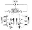
次ぎに、液量及び液温に対する制御フローについて図5に基づいて説明する。
スタートと同時に通電制御手段22aに通電し、水位0ccより上であるか確認した後、温
度測定されて温度基準に照らし合わされ、基準より高いと次の液温検知手段22及び液温表示手段26並びに液量検知手段23及び液量表示手段27を起動させない。勿論通電制御手段22aで水位が0ccであれば同様に次の液温検知手段22及び液温表示手段26並
びに液量検知手段23及び液量表示手段27を起動させない。更に、温度基準値より低いと次の液温検知手段22及び液温表示手段26並びに液量検知手段23及び液量表示手段27を起動する。
Next, a control flow for the liquid amount and the liquid temperature will be described with reference to FIG.
The energization control means 22a is energized at the same time as the start, and after confirming whether the water level is above 0 cc, the temperature is measured and compared with the temperature reference, and if higher than the reference, the next liquid temperature detection means 22 and the liquid temperature display means 26 and The liquid quantity detection means 23 and the liquid quantity display means 27 are not activated. Of course, if the water level is 0 cc in the energization control means 22a, similarly, the next liquid temperature detection means 22, liquid temperature display means 26, liquid amount detection means 23 and liquid amount display means 27 are not activated. Further, when the temperature is lower than the reference temperature, the next liquid temperature detecting means 22 and liquid temperature display means 26, liquid amount detecting means 23 and liquid amount display means 27 are activated.
通電制御手段22aで測定された温度が16℃以上であれば基準より高いとして温度計のシルエットが消灯し、スタート時点へ戻り、起動した液温検知手段22と液温表示手段23により15℃以下であれば基準より低いと判断され次の液温の基準に照らし合わされる。15℃以下であれば、点灯と同時にぬるいの表示を示し、5℃〜10℃であれば点灯と同時に適温の表示を示し、4℃以下であれば点灯と同時に冷たいの表示を順次示すこととなる。 If the temperature measured by the energization control means 22a is 16 ° C. or higher, the thermometer silhouette is turned off because the temperature is higher than the reference, and the temperature returns to the start point. If so, it is judged that the temperature is lower than the standard, and is compared with the standard of the next liquid temperature. If it is 15 ° C or lower, it will indicate a lukewarm display simultaneously with lighting, if it is 5 ° C to 10 ° C, it will indicate an appropriate temperature simultaneously with lighting, and if it is 4 ° C or lower, it will indicate a cold display simultaneously with lighting. Become.
又同様に、通電制御手段22aで測定された液量が0ccであれば基準より低いとして液体
容器のシルエットが消灯し、スタート時点へ戻り、起動した液量検知手段21及び液量表示手段16により内容器内の残量が760ccまでの少しでもあれば基準より高いと判断さ
れ次の液量の基準に照らし合わされる。この工程を順次繰り返し行い、液体容器のシルエットとして残量表示されることとなり、液体容器内の水の利用に伴い各基準へと戻る。
このようにして表示板29の表面に液温と液量とを表示するようにしている。
Similarly, if the amount of liquid measured by the energization control means 22a is 0 cc, the silhouette of the liquid container is extinguished because it is lower than the reference, the process returns to the start time, and the activated liquid amount detection means 21 and the liquid amount display means 16 If the remaining amount in the inner container is a little up to 760 cc, it is judged that it is higher than the standard, and is compared with the standard of the next liquid amount. This process is sequentially repeated, and the remaining amount is displayed as a silhouette of the liquid container, and returns to the respective standards as the water in the liquid container is used.
In this way, the liquid temperature and the liquid amount are displayed on the surface of the
以上本考案の代表的と思われる実施例について説明したが、本考案は必ずしもこれら実施例構造のみに限定されるものではなく、例えば内容器を外装ケースで囲んだ卓上型魔法瓶のように本考案にいう前記の構成要件を備え、かつ、本考案にいう目的を達成し、本考案にいう効果を有する範囲内において適宜改変して実施することができるものである。 Although the embodiments considered to be representative of the present invention have been described above, the present invention is not necessarily limited to the structures of these embodiments. For example, the present invention is like a desktop thermos in which an inner container is surrounded by an outer case. The above-described constituent requirements are provided, the object of the present invention is achieved, and the present invention can be implemented with appropriate modifications within the scope of the effects of the present invention.
1…液体容器
2…内容器
5…蓋体
6…液温・液量検知ユニット
22…液温検知手段
22a…通電制御手段
23…液量検知手段
24…メイン制御基板
25…パルス電圧発生器
26…液温表示手段
27…液量表示手段
28…電源
29…表示板
30…ユニット外装体
31…感温素子
32…液温変換手段
33…電極基板
34…−の電極子
35,35…+の電極子
36…液量変換手段
DESCRIPTION OF
Claims (1)
Priority Applications (1)
| Application Number | Priority Date | Filing Date | Title |
|---|---|---|---|
| JP2008008032U JP3148076U (en) | 2008-11-17 | 2008-11-17 | Liquid container |
Applications Claiming Priority (1)
| Application Number | Priority Date | Filing Date | Title |
|---|---|---|---|
| JP2008008032U JP3148076U (en) | 2008-11-17 | 2008-11-17 | Liquid container |
Publications (1)
| Publication Number | Publication Date |
|---|---|
| JP3148076U true JP3148076U (en) | 2009-01-29 |
Family
ID=54781661
Family Applications (1)
| Application Number | Title | Priority Date | Filing Date |
|---|---|---|---|
| JP2008008032U Expired - Lifetime JP3148076U (en) | 2008-11-17 | 2008-11-17 | Liquid container |
Country Status (1)
| Country | Link |
|---|---|
| JP (1) | JP3148076U (en) |
-
2008
- 2008-11-17 JP JP2008008032U patent/JP3148076U/en not_active Expired - Lifetime
Similar Documents
| Publication | Publication Date | Title |
|---|---|---|
| US7681446B2 (en) | Liquid container | |
| US8350571B2 (en) | Electronic salt meter | |
| AU2009100811A4 (en) | Improved temperature sensor for an electric kettle | |
| JP5057873B2 (en) | Liquid container | |
| JP5011083B2 (en) | Liquid volume / liquid temperature detection unit for liquid containers | |
| CN212661648U (en) | Kettle | |
| JP3148076U (en) | Liquid container | |
| JP5414199B2 (en) | Liquid container | |
| CN205162640U (en) | Intelligent water glass | |
| CN101467832B (en) | Liquid container | |
| CN205018825U (en) | Insulating pot and water level suggestion device that is used for insulating pot | |
| JP5084358B2 (en) | Liquid container | |
| JP4250659B2 (en) | Liquid container | |
| JPH10262826A (en) | Electric pot | |
| JP2008264141A (en) | Liquid container | |
| CN108143268A (en) | Intelligent electric-heating water system | |
| CN208524544U (en) | A kind of intelligent base of insulating pot | |
| JP2000316721A (en) | Liquid amount display device for liquid storage container and liquid amount display method therewith | |
| CN210124603U (en) | Liquid heating container | |
| JPH0638771B2 (en) | Electric kettle pot | |
| CN218419418U (en) | Kettle and tea bar machine | |
| KR20120058282A (en) | The Kettle Having Temperature Controlling Function | |
| JPH0614691Y2 (en) | Electric hot water storage container | |
| JPH0211110A (en) | Microcomputer controlled electric pot | |
| GB2422770A (en) | Electric boiler |
Legal Events
| Date | Code | Title | Description |
|---|---|---|---|
| R150 | Certificate of patent or registration of utility model |
Free format text: JAPANESE INTERMEDIATE CODE: R150 |
|
| FPAY | Renewal fee payment (event date is renewal date of database) |
Free format text: PAYMENT UNTIL: 20150107 Year of fee payment: 6 |
|
| R250 | Receipt of annual fees |
Free format text: JAPANESE INTERMEDIATE CODE: R250 |
|
| R250 | Receipt of annual fees |
Free format text: JAPANESE INTERMEDIATE CODE: R250 |
|
| R250 | Receipt of annual fees |
Free format text: JAPANESE INTERMEDIATE CODE: R250 |
|
| R250 | Receipt of annual fees |
Free format text: JAPANESE INTERMEDIATE CODE: R250 |
|
| EXPY | Cancellation because of completion of term |