JP3148945U - Suction wind type sorter - Google Patents
Suction wind type sorter Download PDFInfo
- Publication number
- JP3148945U JP3148945U JP2008008972U JP2008008972U JP3148945U JP 3148945 U JP3148945 U JP 3148945U JP 2008008972 U JP2008008972 U JP 2008008972U JP 2008008972 U JP2008008972 U JP 2008008972U JP 3148945 U JP3148945 U JP 3148945U
- Authority
- JP
- Japan
- Prior art keywords
- suction
- air
- raw material
- sorting
- chute member
- Prior art date
- Legal status (The legal status is an assumption and is not a legal conclusion. Google has not performed a legal analysis and makes no representation as to the accuracy of the status listed.)
- Expired - Lifetime
Links
Images


Landscapes
- Combined Means For Separation Of Solids (AREA)
Abstract
【課題】小型かつ簡素な構成で、複数の材料からなる原料から、大きさ別、重量別の材料に選別を行うことができる吸引風力式選別装置の提供。【解決手段】本考案は、複数の材料が含まれた原料から、所定の材料に選別するための吸引風力式選別装置である。所定の大きさのふるい目を有する傾斜スクリーンに振動を付与し、所定の大きさ以下の材料を選別する第1の選別手段10と、傾斜スクリーンの他方の側に設けられ、傾斜スクリーンから落下しなかった原料が移動してくるシュート部材70と、シュート部材70上の原料から軽量な材料を吸引し、選別する第2の選別手段20と、吸引用空気を生成するための吸引空気生成手段80と、排気口から排気される空気の一部を分岐し、シュート部材の下方近傍から吹き出して、傾斜スクリーン側の埃、粉塵等が吸引空気生成手段の吸引口から吸い込まれるのを防止する埃流入防止手段88、89とを備えている。【選択図】図1The present invention provides a suction wind type sorting apparatus capable of sorting materials by size and weight from raw materials made of a plurality of materials with a small and simple configuration. The present invention is a suction wind type sorting apparatus for sorting a predetermined material from a raw material containing a plurality of materials. A first sorting means 10 is provided on the other side of the tilting screen for applying vibration to the tilting screen having a sieve having a predetermined size and sorting materials having a predetermined size or less, and falls from the tilting screen. The chute member 70 from which the raw material that has not moved moves, the second sorting means 20 that sucks and sorts a lightweight material from the raw material on the chute member 70, and the suction air generating means 80 for generating suction air And a part of the air exhausted from the exhaust port and blown out from near the bottom of the chute member to prevent dust, dust, etc. on the inclined screen side from being sucked from the suction port of the suction air generating means Prevention means 88, 89. [Selection] Figure 1
Description
本考案は、建築廃材、混合産業廃棄物等原料を、リサイクル容易な大きさ別、重量別の材料に選別するための吸引風力式選別装置に関する。さらに詳しくは、小型、かつ、簡素な構成であるとともに、排気される空気に含有する埃、粉塵等を減少させることが可能な吸引風力式選別装置に関する。 The present invention relates to a suction wind type sorting device for sorting materials such as building waste and mixed industrial waste into materials that are easily recyclable by size and weight. More specifically, the present invention relates to a suction wind type sorting apparatus that has a small and simple configuration and can reduce dust, dust, and the like contained in the exhausted air.
コンクリート廃材、アスファルト廃材等の建築廃材は、建築工事、解体工事、土木工事などにおいて、建設副産物(建設廃棄物)として排出される。この建設副産物は、産業廃棄物として廃棄するのでなく有効利用することが求められている。すなわち、建築廃材は、ふるい装置により、所定の大きさ(例えば40mm)以上の物と所定の大きさ以下の物とに分ける粗ぶるいを行い、再生路盤材などとして再利用するとよい。しかし、建築廃材には、木くず、紙、プラスチックなどいろいろな物が混ざっており、そのままでは再利用することができない。 Construction waste such as concrete waste and asphalt waste is discharged as construction by-products (construction waste) in construction work, dismantling work, civil engineering work, etc. This construction by-product is required to be effectively used rather than discarded as industrial waste. That is, the building waste material may be reused as a recycled roadbed material or the like by performing coarse sieving by dividing it into an object having a predetermined size (for example, 40 mm) or more and an object having a predetermined size or less by a sieve device. However, building waste materials contain various materials such as wood chips, paper, and plastic, and cannot be reused as they are.
言い換えると、所定の大きさ以下に分別したものは、例えば、再生路盤材などとして利用可能であるが、その建築廃材の中に木くず、紙、プラスチックなど不純物(ゴミ)が多く混ざっていると、再生路盤材等に再利用することができない。そこで、建築廃材は、作業者による手選別で、木くず、紙、プラスチックなどを選別して取り除く作業が必要であった。 In other words, what is separated below a predetermined size can be used as recycled roadbed materials, for example, but if there are many impurities (trash) such as wood chips, paper, plastic, etc. in the building waste, It cannot be reused for recycled roadbed materials. Therefore, it was necessary for the construction waste materials to be manually removed by the operator to sort and remove wood chips, paper, plastics, and the like.
しかしながら、建築廃材、混合産業廃棄物から不純物を取り除く作業の多くは手選別であり、たいへんな作業である。また、混合産業廃棄物の小さい物(例えば、40mm以下のもの)は、手選別が容易でなく、埋め立て処理されてしまうことが多い。そのため、自動で選別することが可能な選別装置、選別方法、選別システムが、種々、提案されている。このような選別装置等について、特許文献を例にとって、さらに説明を行う。 However, most of the work to remove impurities from building waste and mixed industrial waste is manual sorting, which is a very difficult work. In addition, small mixed industrial waste (for example, 40 mm or less) is not easy to manually sort and is often landfilled. Therefore, various sorters, sort methods, and sort systems that can sort automatically have been proposed. Such a sorter will be further described with reference to patent literature as an example.
従来の建築廃材の処理システムとして、スクリーン及び振動付与機構を有する振動ふるい装置と、吸引ノズル、サイクロン及びファン装置を有する不純物除去装置と、吸引ノズル下方のスリット網に下方から風を送る第1の送風機構とを具備しているものが知られている(例えば、特許文献1参照)。この特許文献1の建築廃材の処理システムでは、建設廃材が、振動ふるい装置のスクリーンにおいてふるい分けられ、スクリーンをオーバーしたオーバー材はスリット網側へ送られ、比較的軽量な不純物が吸引ノズルにより吸引除去されている。 As a conventional construction waste treatment system, a vibration sieving device having a screen and a vibration imparting mechanism, an impurity removing device having a suction nozzle, a cyclone and a fan device, and a first sending air from below to a slit network below the suction nozzle What is equipped with the ventilation mechanism is known (for example, refer patent document 1). In the construction waste processing system disclosed in Patent Document 1, construction waste is screened on a screen of a vibration sieving device, and the over material over the screen is sent to the slit mesh side, and relatively lightweight impurities are removed by suction using a suction nozzle. Has been.
また、風力選別を利用した再生路盤材の回収方法として、コンクリート廃材やアスファルト廃材等を破砕装置に供給して所定の大きさに破砕し、破砕された廃棄物をふるい装置に供給して所定粒度毎にふるい分けして再生骨材及び再生路盤材を回収する方法が知られている(例えば、特許文献2参照)。この特許文献2の回収方法では、送風機によって振動傾斜ふるい装置の下段ふるいを通過できずに傾斜下端部から落下する成分のうち、軽量成分を吹き飛ばし、吹き飛ばされずに落下した重量成分と分けて回収できる。 In addition, as a method for recovering recycled roadbed materials using wind sorting, concrete waste, asphalt waste, etc. are supplied to a crushing device and crushed to a predetermined size, and the crushed waste is supplied to a sieving device to obtain a predetermined particle size. There is known a method of collecting the recycled aggregate and the recycled roadbed material by sieving every time (see, for example, Patent Document 2). In the recovery method of Patent Document 2, among the components falling from the lower end of the tilt without being able to pass through the lower screen of the vibration tilt screen by the blower, the light weight component is blown away, and the weight component that has fallen without being blown can be recovered separately. .
さらに、空き缶や空き瓶等の固形ごみと収容袋等の可塑性ごみとが混在した混合ごみを落下させる落下シュートの途中に、収容袋等の可塑性ごみを空気の吸引力により網状コンベアベルトの表面に吸着させた状態で落下シュート3の別の箇所まで搬送する吸引選別手段を備えた風力選別装置が知られている(例えば、特許文献3参照)。
しかしながら、特許文献1に記載された技術では、不純物を除去するためにサイクロンを必要とするなど、設備が大型化し、設備費も高額なものとなり、メンテナンスも容易でないという問題点があった。また、特許文献2に記載された技術では、再生路盤材と、不純物との選別が充分でなく、良質の再生路盤材、骨材が得られないおそれがあるとともに、ふるい装置の下方側に埃、粉塵等が飛散し、環境低下が生じるおそれがあるという問題点があった。さらに、特許文献3に記載された技術でも、集塵器が必須であり、設備の大型化、設備費増大などの問題は解消されていない。 However, the technique described in Patent Document 1 has a problem that the equipment is enlarged, the equipment cost is high, and the maintenance is not easy, such as requiring a cyclone to remove impurities. Moreover, in the technique described in Patent Document 2, there is a risk that the regenerated roadbed material and the impurities are not sufficiently selected, and a high-quality regenerated roadbed material and aggregate may not be obtained. In addition, there is a problem that dust or the like may be scattered and environmental degradation may occur. Furthermore, even with the technique described in Patent Document 3, a dust collector is essential, and problems such as an increase in equipment size and an increase in equipment costs have not been solved.
このような現状から、サイクロン等集塵装置を必要とせず、小型、かつ、簡素な装置で、信頼性の高い選別ができる風力式選別装置の開発が要望されていた。また、サイクロン等集塵装置を設けなくとも、排気口から排気される空気に含有される埃、粉塵等を減少させることが可能な風力式選別装置の開発が要望されていた。 Under such circumstances, there has been a demand for the development of a wind-type sorting device that does not require a dust collector such as a cyclone, and that can perform sorting with high reliability with a small and simple device. Further, there has been a demand for the development of a wind power sorting device that can reduce dust, dust, and the like contained in the air exhausted from the exhaust port without providing a dust collector such as a cyclone.
本考案は、前記した問題点を解決するためになされたもので、下記の目的を達成する。
本考案の目的は、小型かつ簡素な構成で、複数の材料からなる原料から、大きさ別、重量別の材料に、確実に選別を行うことができるとともに、排気口から排気する空気に含有される埃、粉塵等を減少させることが可能な吸引風力式選別装置を提供することにある。
The present invention has been made to solve the above-described problems and achieves the following object.
The object of the present invention is to have a small and simple configuration, which can reliably sort a material by a size and a weight by a plurality of materials, and is contained in air exhausted from an exhaust port. An object of the present invention is to provide a suction wind power sorter that can reduce dust, dust and the like.
本考案は、前記目的を達成するために次の手段をとる。
本考案1の吸引風力式選別装置は、複数の材料が含まれた原料から、所定の材料に選別するための吸引風力式選別装置であって、水平面に対して一方の側が高くなる第1の角度傾斜しているとともに、所定の大きさのふるい目を有する傾斜スクリーンに振動を付与し、前記一方の側から供給された前記原料が前記一方の側から他方の側に移動している間に、所定の大きさ以下の材料を、前記ふるい目を介して前記傾斜スクリーンの下方側に落下させて選別する第1の選別手段と、前記傾斜スクリーンの他方の側の先端に設けられ、前記第1の角度より小さい第2の角度に傾斜し、前記傾斜スクリーンから落下しなかった前記原料が移動してくるシュート部材と、前記シュート部材の上方に、前記原料の移動方向を横切るように設けられ、前記シュート部材上の前記原料から軽量な原料を吸引して前記横切る方向に回収し、所定の大きさ以上であって軽量な材料として選別する第2の選別手段と、前記第2の選別手段側に設けられた吸引口から空気を吸引し、排気口から排気するための送風機と、前記吸引口と前記排気口とを連通させるための空気通路とを有し、前記第2の選別手段の吸引用の空気を生成するための吸引空気生成手段と、前記シュート部材の下方近傍に吹き出し口が設けられ、前記空気通路の中途から分岐された前記空気が前記吹き出し口から前記シュート部材側に吹き出され、前記傾斜スクリーン側の埃及び/又は粉塵が前記吸引口から吸い込まれるのを防止するための埃流入防止手段とを備えていることを特徴とする。
The present invention takes the following means to achieve the object.
The suction wind type sorting device according to the first aspect of the present invention is a suction wind type sorting device for sorting a predetermined material from a raw material containing a plurality of materials. While tilting the angle and applying vibration to the tilt screen having a sieve having a predetermined size, the raw material supplied from the one side is moving from the one side to the other side. A first sorting means for sorting a material having a predetermined size or less by dropping to the lower side of the inclined screen through the sieve screen, and a tip of the other side of the inclined screen; A chute member that is inclined to a second angle smaller than 1 and that has not fallen from the inclined screen, and is provided above the chute member so as to cross the moving direction of the raw material. The above A second sorting means for sucking and collecting a light-weight raw material from the raw material on the lute member in the transverse direction, and sorting it as a light-weight material having a predetermined size or more; and on the second sorting means side A blower for sucking air from the provided suction port and exhausting from the exhaust port; and an air passage for communicating the suction port and the exhaust port, for suction of the second sorting means Suction air generating means for generating the air, and a blow-off port is provided near the lower portion of the chute member, and the air branched from the middle of the air passage is blown out from the blow-out port to the chute member side, Dust inflow prevention means for preventing dust and / or dust on the inclined screen side from being sucked from the suction port is provided.
本考案2の吸引風力式選別装置は、本考案1において、前記第2の選別手段は、空気の流通が可能であるとともに所定の幅を有する無端ベルトであって、前記横切る方向に延びた巻回運動軌跡上を移動可能に、前記巻回運動軌跡の前記シュート部材側の面が、前記シュート部材に対して所定の間隔を有するとともに平行または略平行になるように設けられた巻回ベルトと、前記巻回ベルトを所定の方向に巻回運動させるための巻回駆動機構とを有し、前記吸引口は、前記巻回ベルトの中間に、前記シュート部材側に開口を向けるように設けられたものであることを特徴とする。 The suction wind type sorting device according to the second aspect of the present invention is the suction wind type sorting apparatus according to the first aspect of the invention, wherein the second sorting means is an endless belt capable of circulating air and having a predetermined width, and the winding extends in the transverse direction. A winding belt provided so that a surface on the chute member side of the winding movement locus is parallel to or substantially parallel to the chute member so as to be movable on a turning movement locus; A winding drive mechanism for winding the winding belt in a predetermined direction, and the suction port is provided in the middle of the winding belt so that the opening faces the chute member side. It is characterized by that.
本考案3の吸引風力式選別装置は、本考案2において、前記空気通路の分岐部には、前記排気口側の空気通路に流れる空気の流量と、前記吹き出し口側の空気通路に流れる空気の流量とを調整するための空気流量調整手段が設けられていることを特徴とする。 The suction wind power sorter according to the third aspect of the present invention is the second aspect of the present invention, wherein the branch of the air passage includes a flow rate of air flowing in the air passage on the exhaust port side and a flow of air flowing in the air passage on the outlet side. An air flow rate adjusting means for adjusting the flow rate is provided.
本考案4の吸引風力式選別装置は、本考案3において、前記シュート部材の下方には、前記吹き出し口から吹き出された空気が、前記シュート部材に向って流出するように、前記空気の流れの方向を変えるための流れ方向変更部材が設けられていることを特徴とする。 The suction wind type sorting apparatus according to the present invention 4 is the apparatus of the present invention 3, wherein the air flow is such that air blown out from the blowout port flows out toward the chute member below the chute member. A flow direction changing member for changing the direction is provided.
本考案5の吸引風力式選別装置は、本考案3または4において、前記空気流量調整手段は、前記側面視略1/4円の円弧状の板材を背中合わせに一体化した空気流量調整部材を有し、前記分岐部において、前記空気流量調整部材を移動させることで、空気流量の調整を可能としたものであることを特徴とする。 The suction wind type sorting apparatus according to the present invention 5 is characterized in that, in the present invention 3 or 4, the air flow rate adjusting means includes an air flow rate adjusting member in which the arc-shaped plate members having a substantially 1/4 circle in side view are integrated back to back. Then, the air flow rate can be adjusted by moving the air flow rate adjusting member in the branch portion.
本考案6の吸引風力式選別装置は、本考案5において、前記原料は、建築廃材または混合産業廃棄物であり、前記所定の大きさ以下の材料は、再生路盤材、再生骨材のための材料、残砂から選択される1種以上であり、前記所定の大きさ以上であって軽量な材料は、紙、プラスチック、及び、木片から選択される1種を少なくとも含む不要材料であることを特徴とする。 The suction wind power sorter of the present invention 6 is the present invention 5, wherein the raw material is building waste or mixed industrial waste, and the material having a predetermined size or less is for recycled roadbed material and recycled aggregate. It is one or more types selected from materials and residual sand, and the light material that is not less than the predetermined size and lightweight is an unnecessary material including at least one selected from paper, plastic, and wood chips. Features.
以上、説明したように、本考案の吸引風力式選別装置は、本来、排気される空気をシュート部材近傍に設けられた吹き出し口から吹き出し、吸引口から傾斜スクリーン側の埃、粉塵等を吸い込みにくくしている。このような構成とすることで、排気口から排気される空気に含有される埃、粉塵等の量を少なくすることができ、吸引風力式選別装置の排気口周辺の環境悪化を防止している。言い換えると、作業者が操作を行う領域近傍に排気される埃、粉塵等の量を少なくすることができる。 As described above, the suction wind-type sorting device of the present invention originally blows out the exhausted air from the outlet provided in the vicinity of the chute member, and hardly sucks dust, dust, etc. on the inclined screen side from the inlet. is doing. By adopting such a configuration, it is possible to reduce the amount of dust, dust, and the like contained in the air exhausted from the exhaust port, and to prevent deterioration of the environment around the exhaust port of the suction wind type sorting device. . In other words, it is possible to reduce the amount of dust, dust, and the like that are exhausted in the vicinity of the region where the operator operates.
また、空気を、排気するための空気通路から分岐してシュート部近傍に吹き出すだけの簡素な構成であり、メンテナンスも不要で低コストを実現できる。さらに、分岐部に空気流量調整手段を備え、選別する原料の種類等に合わせて、前記排気口側空気通路を流れる空気流量と、前記空気吹き出し口側空気通路を流れる空気流量とを、容易に調整することが可能である。 Further, the air is simply configured to be branched from the air passage for exhausting and blown to the vicinity of the chute portion, so that maintenance is not required and low cost can be realized. Furthermore, an air flow rate adjusting means is provided at the branch portion, and the air flow rate flowing through the exhaust port side air passage and the air flow rate flowing through the air outlet side air passage can be easily adjusted in accordance with the type of raw material to be selected. It is possible to adjust.
さらに、第1の選別手段で所定の大きさ以下の材料の選別を行い、第2の選別手段で、所定の大きさ以上であって重量が軽い材料、所定の大きさ以上であって重量が重い材料に選別することができるようになった。すなわち、リサイクル(再利用)可能な材料として好適なものを選別回収することができる。 Further, the first sorting means sorts materials having a predetermined size or less, and the second sorting means uses a material that is not less than a predetermined size and light in weight. It became possible to sort into heavy materials. That is, it is possible to select and collect materials suitable as recyclable (reusable) materials.
すなわち、本考案の吸引風力式選別装置では、建築廃材を、リサイクル可能な再生路盤材、再生骨材と不要材料(または、ゴミ)とに、容易に選別、回収することができる。また、混合産業廃棄物を、リサイクル可能な残砂と不要材料(がれき類、木、紙、プラスチック等)とに容易に選別、回収することができる。 That is, in the suction wind power sorter of the present invention, building waste can be easily sorted and collected into recyclable recycled roadbed material, recycled aggregate and unnecessary material (or garbage). In addition, mixed industrial waste can be easily sorted and collected into recyclable residual sand and unnecessary materials (such as debris, wood, paper, and plastic).
以下、本考案の吸引風力式選別装置について、図面に基づいて、その実施の形態を詳細に説明する。 Hereinafter, the suction wind type sorting device of the present invention will be described in detail based on the drawings.
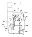
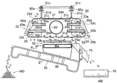
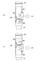
図1は、本考案の実施の形態の吸引風力式選別装置を示す正面図、図2は、側面図である。図3は、図1のX−X線で切断して示した断面図である。図4は、図3をY−Y線で切断して示した断面図である。図5は、空気流量調整部材の調整位置と空気流量との関係を模式的に示した説明図であり、(a)は排気ダクト側に多くの空気を流している状態を示し、(b)は還流用ダクト側に多くの空気を流している状態を示している。 FIG. 1 is a front view showing a suction wind type sorting apparatus according to an embodiment of the present invention, and FIG. 2 is a side view. FIG. 3 is a cross-sectional view taken along line XX of FIG. FIG. 4 is a cross-sectional view taken along line YY of FIG. FIG. 5 is an explanatory view schematically showing the relationship between the adjustment position of the air flow rate adjusting member and the air flow rate, where (a) shows a state in which a large amount of air is flowing to the exhaust duct side, and (b) Indicates a state in which a large amount of air is flowing to the reflux duct side.
図1〜4に示すように、本実施の形態の吸引風力式選別装置1は、振動ふるい選別手段(第1の選別手段)10、吸引選別手段(第2の選別手段)20、選別装置本体(以下、本体という。)50、ベルトコンベア60等から構成されている。なお、この実施の形態の説明では、図1における吸引選別手段20側を前方側(他方の側)、制御装置72側を後方側(一方の側)として説明を行う。
As shown in FIGS. 1 to 4, the suction wind type sorting device 1 of the present embodiment includes a vibrating screen sorting means (first sorting means) 10, a suction sorting means (second sorting means) 20, and a sorting apparatus main body. (Hereinafter referred to as the main body) 50, a
本体50にはキャスター52、52が設けられている。すなわち、キャスター52、52は、本体50に形成された支持脚53a、53bを介して取り付けられている。このような構成とすることで、所定の位置(例えば、選別作業を行う位置)に移動可能になっている。また、トラック等運搬手段で運搬後、選別作業を行う現場、リサイクルを行う現場等へ移動することも容易である。なお、吸引風力式選別装置は、このキャスター構成に限定されることはなく、本体にクローラ、クローラ駆動装置を設け、走行可能にしたものであってもよい。このような構成にすると、クローラ駆動装置によりクローラを駆動し、選別作業を行う現場、リサイクルを行う現場等に自走して移動することができる。
The
本体50の下部には、ベルトコンベア60が設けられている。ベルトコンベア60は、コンベア本体に対して、無端状のベルト61が駆動モータ(図示せず)の駆動により、矢印Pの方向に移動可能に構成されている。このようなベルトコンベアは周知なものであり、この実施の形態の説明では、これ以上詳説しない。
A
本体50の後方側には、ベルトコンベア60、振動ふるい選別手段10の加振装置13等の操作を行うための操作盤が設けられた制御装置72が設けられている。制御装置72は、作業者が操作する操作盤からの操作指令に従って、ベルトコンベア60、加振装置13等の制御を行う。
On the rear side of the
図1に示すように、本体50の上部に設けられた振動ふるい選別手段(第1の選別手段)10は、ふるい枠体11、傾斜スクリーン12、加振装置13、弾性支持体16等から構成されている。ふるい枠体11は、本体50に対して弾性支持体16を介して弾性支持されている。ふるい枠体11には、原料を投入(供給)するための原料投入部11aが設けられている。弾性支持体16は、ばね部材17を備えている。本体50とふるい枠体11の間には、加振装置13が設けられている。加振装置13は、加振モータ14が回転するとベルトを介して回転し、ふるい枠体11に振動させるものである。
As shown in FIG. 1, a vibrating screen sorting means (first sorting means) 10 provided in the upper part of the
ふるい枠体11の内部には、所定の大きさ(例えば40mm)のメッシュ(ふるい目)を有する傾斜スクリーン12が設けられている。傾斜スクリーン12は、支持部材12aを介してふるい枠体11に支持されている。傾斜スクリーン12は、後方側(一方の側)が高く、前方側であるシュート部材70側(他方の側)が低くなるような所定の角度(第1の角度)の傾斜をしている。傾斜スクリーン12に供給された原料Gは、この傾斜と、傾斜スクリーン12に付与される振動とによって、前方側(矢印Qの方向)に移動する。
An
投入された原料は、振動ふるい選別手段10でふるわれ、所定の大きさ以下の原料は、傾斜スクリーン12のメッシュを介して落下し選別される。落下したものは、ベルトコンベア60のベルトの矢印P方向への移動によって、所定の大きさ以下の材料MAとして、吸引風力式選別装置1の後方側の選別収集位置に収集される。
The charged raw material is sieved by the vibrating screen sorting means 10, and the raw material having a predetermined size or less falls through the mesh of the
傾斜スクリーン12の前端側には、振動ふるい選別手段10でふるわれて落下しなかった原料、言い換えると所定の大きさ以上の原料が移動してくるシュート部材70が設けられている。シュート部材70は、ふるい枠体11の前端部に固定され、底面部70aと側面部70bとから形成されている(図3参照)。底面部70aは、網目状、長目状、格子状、くし状等に穴、溝等が形成され、空気の流通がたいへんよい形状の部材になっている。このシュート部材70は、傾斜スクリーン12が傾斜している第1の角度より小さい第2の角度に傾斜している。すなわち、シュート部材70は、水平面に対して、ほぼ水平または緩い傾斜になっている。シュート部材70が傾斜している第2の角度は、例えば、0〜5度の傾斜であるとよい。言い換えると、シュート部材70が傾斜している第2の角度は、傾斜スクリーン12が傾斜している第1の角度に比べ、大幅に小さな角度となっている。
On the front end side of the
すなわち、投入され、ふるわれた原料は、この緩い傾斜面である底面部70a上を移動することにより、一時滞留したり、大幅に遅い速度で移動することになる。言い換えると、後から移動してくる原料に押される力と付与される振動によって、シュート部材70の前方側に押されるように移動する。
なお、シュート部材70は、ふるい枠体11に対して取付角度の調整が可能になっているとよい。また、本体50には、傾斜板部材55が設けられている。傾斜板部材55は、振動ふるい選別手段10でふるわれたとき落下せずに残り、シュート部材70から落下してくる少量の粉状の原料をベルトコンベア60に流入させるようにしているものである。
That is, the charged and sieved raw material moves temporarily on the
Note that the
シュート部材70上の所定の大きさ以上の原料は、吸引選別手段(第2の選別手段)20によって、吸引されて移動される所定の大きさ以上で軽い原料と、吸引されない所定の大きさ以上で重い原料に吸引選別される。吸引されない所定の大きさ以上で重い原料は、シュート部材70上を押し出されるように移動し、前端側から排出され第2ベルトコンベア95上に落下する。落下した所定の大きさ以上で重い原料は、第2ベルトコンベア95のベルトの矢印R方向への移動によって搬送され、吸引風力式選別装置1の側方の一方の側(図3における左側)に、所定の大きさ以上であって重量が重い材料MDとして選別回収される。なお、この実施の形態でいう「所定の大きさ以上で軽い原料」には、吸引表面積(風受面積)の大きい原料(ただし、球状のものを除く)を含んでいるものとする。
A raw material of a predetermined size or larger on the
所定の大きさ以上であって重量が軽い原料は、吸引選別手段20、搬出シュート75を介して、吸引風力式選別装置1の側方の他方の側(図3における右側)に、所定の大きさ以上であって重量が軽い材料MBとして選別回収される。吸引選別手段20について、さらに説明を行う。
A raw material that is not less than a predetermined size and light in weight has a predetermined size on the other side (the right side in FIG. 3) of the suction wind power sorter 1 via the suction sorting means 20 and the carry-out
支持台81には、支柱82、片持ち梁部材82a、梁部材82bが設けられている。梁部材82bは、支柱82、82の上部を固定するように設けられている。梁部材82b上には、片持ち梁部材82aが固定されている。片持ち梁部材82aには、吸引選別手段20の吸引枠体21が吊設されている。すなわち、吸引枠体21の被取付部21cが吊り下げボルト51bで吊り下げられ、ナット51c等により片持ち梁部材82aに固定されている。吸引枠体21には、メッシュコンベア22が支持されている。片持ち梁部材82aの先端には固定部材82cがボルト等締結部材で固定されている。
The
シュート部材70の上方には、吸引選別手段20の吸引枠体21が設けられている。吸引枠体21は、略直方体状のものであり、下側(シュート部材側)が開口していて吸引口21aを形成している。吸引口21aの搬出シュート75側には、側面視、三角状の三角状吸引口21dが形成されている。この三角状吸引口21dは、吸引口21a側より、吸引する風力を除々に小さくするためのものであり、吸引した軽い原料が自重により落下することを補助するためのものである。また、吸引枠体20の一方の側面には、吸引ダクト83が接続される吸引ダクト接続口が形成されている。
Above the
吸引枠体20の両方の側面には、各々、一対の取付部材65a、取付部材65bがボルト等締結部材で固定されている。取付部材65a、取付部材65bは、みぞ形鋼などであるとよい。
一対の取付部材65a、65aには軸受ユニット60a、60dが取り付けられている。一対の取付部材65b、65bには軸受ユニット60b、60cが取り付けられている。軸受ユニット60c、60cは、支持ローラ23cが設けられている軸体62cの両端を回転可能に支持している。また、軸受ユニット60d、60dは、支持ローラ23dが設けられている軸体62dの両端を回転可能に支持している。同様に、軸受ユニット60a、60aが、支持ローラ23aが設けられている軸体の両端を、軸受ユニット60b、60bが、支持ローラ23bが設けられている軸体の両端を回転可能に支持している。
A pair of
支持ローラ23a、23b、23c、23dには、メッシュ状巻回ベルト24が、図3に図示したような略台形状の移動軌跡上を回転動作可能に巻回されている。軸体62cの一方の側には、メッシュコンベア用駆動モータ25が設けられ、軸体62cを回転駆動している。すなわち、巻回ベルト用駆動モータ25が軸体62cを回転駆動すると、メッシュ状巻回ベルト24は、支持ローラ23a、23b、23c、23dに支持されて回転する。また、メッシュ状巻回ベルト24は、略台形状の移動軌跡の両側辺部がカバー部材65c、65cでカバーされており、巻回運動するメッシュ状巻回ベルト24から作業者を守り、安全性向上を図っている。
A mesh-like winding
メッシュコンベア22は、支持ローラ23a〜23d、支持ローラ23a〜23d間に巻回されているメッシュ状巻回ベルト24、メッシュコンベア用駆動モータ25等から構成されている。
メッシュ状巻回ベルト24には、ガイド部24aが形成されており、支持ローラ23a、23b、23c、23dに形成されたガイド溝部に係合している。メッシュ状巻回ベルト24は、ガイド部24aが支持ローラのガイド溝部に係合して回転することにより、蛇行などしないようになっている。メッシュ状巻回ベルト24は、所定の幅、長さを有する無端ベルトである。
The
A
メッシュ状巻回ベルト24は、所定の大きさの孔(例えば、丸孔、角穴、長孔、亀甲孔)が複数形成された薄板状のベルト、長目状のメッシュベルト等であってもよく、要するに、支持ローラ間を巻回できるとともに、そのベルト面の孔を介して空気の流通がたいへんよいものであればよい。メッシュ状巻回ベルトは、薄板金属、合成樹脂などで製作されているとよい。
The mesh-shaped winding
メッシュ状巻回ベルト24は、原料が傾斜スクリーン12上を移動していく原料移動方向を横切る方向に延びた巻回運動軌跡上を、支持ローラ23a、23b、23c、23dに支持されて巻回運動する。また、メッシュ状巻回ベルト24は、少なくともシュート部材70の上部を移動するベルト面が、シュート部材70の面に対して、所定の間隔を有するとともに、平行または略平行に移動するように設けられて巻回する。
The mesh-shaped winding
吸引枠体21の吸引口21a側には、メッシュ状巻回ベルト24が吸引する風力によって、内側に変形しない(引き込まれない)ように、複数(この形態では、吸引枠体21の両側と中央に各々5個)のガイドローラが設けられている。このガイドローラは、いわゆるカムフォロワ(ローラフォロワ)などと呼ばれているものが使用できる。ガイドローラは、軸部が吸引枠体21に形成された穴部を挿通し、ナット64aで吸引枠体21に固定されている。吸引枠体21には、ロールブラシ状の軽材料分離部材63が設けられている。すなわち、軽材料分離部材63のブラシの先端が、メッシュ状巻回ベルト24の網目内に入って、メッシュ状巻回ベルト24と吸引された軽い原料との分離を図ることができる。
A plurality of (in this embodiment, both sides and the center of the
また、メッシュ状巻回ベルト24には、長手方向の所定の間隔毎に、横桟部24bが設けられている。この横桟部24bは、長く薄い原料がメッシュ状巻回ベルト24に吸着されてしまうのを防止したり、吸引力が低下する位置またはなくなる位置で、吸引した軽い原料が自重で落下するのを容易にするためのものである。なお、メッシュ状巻回ベルトは、横桟部が設けられていないものであってもよい。
Further, the
吸引本体21の吸引ダクト接続口には、吸引ダクト83の一方が接続されている。吸引ダクト83の他方は、送風機84の吸込口に接続されている。すなわち、送風機84の作用により、吸引口21a近傍の空気は、吸引口21aから矢印B方向に吸引される。送風機84の吐出口には、分岐ダクト(分岐部)88aが接続されている。分岐ダクト88aの一方の側には、排気口87が形成された排気ダクト86が接続されている。分岐ダクト88aの他方の側には、吹き出し口89aが形成された還流用ダクト89が接続されている。還流用ダクト89は、送風機84の取り付け台84bの後側まで延びた後、送風機84の取り付け台84bの間を、シュート部材70の方向に戻り、上方向に立ち上がるように形成されている。吸引ダクト83、排気ダクト86、分岐ダクト88a、還流用ダクト89の内部(内側の空間部)が、各々、吸引用空気通路、排気用空気通路、分岐用空気通路、還流用空気通路を形成する。
One end of the
吹き出し口89aは、開口部がシュート部材70の方向を向いているとともに、シュート部材70より所定量下方に位置している。第2ベルトコンベア95の上部には、ホッパー96が設けられており、シュート部材70の前端側から排出される所定の大きさ以上で重い原料が、確実に、第2ベルトコンベア95上に落下するように誘導している。ホッパー96の上部には、傾斜板部材97が設けられており、振動ふるい選別手段10でふるわれたとき落下せずに残り、シュート部材70から落下してくる少量の粉状の原料を第2ベルトコンベア95に流入させるようにしている。また、傾斜板部材97は、吹き出し口89aから吹き出された空気の流れの向きを傾斜板部材97の角度に沿った方向(矢印C方向)に変える役割もしている。この空気の流れは、いわゆるエアカーテンのような役割をはたす。
The
送風機84は、送風機用駆動モータ85に駆動されるファン等で送風動作を行う。送風機84は、操作盤が前面に設けられた送風機用制御盤84aで制御される。作業者は、この送風機用制御盤84aの操作盤を操作することで、送風機用駆動モータ85の出力を調整し、送風機84が発生する風力の調整を行うことができる。例えば、選別される原料の種類、軽い材料として吸引される材料の種類等により、メッシュ状巻回ベルト24のベルト面を介して吸引する吸引力に相当する送風機84の風力調整を行うことができる。送風機84、吸引ダクト83、排気ダクト86、送風機用駆動モータ85等により吸引空気生成手段(送風手段)80が構成されている。
The
分岐ダクト88a内には、空気流量調整部材88b、ストッパ部材88c、ストッパ部材88dが設けられている。空気流量調整部材88bは、側面視略1/4円の円弧状の板材を背中合わせに一体化したものであり、分岐ダクト88a内を、図2における上下方向に移動させることで、送風機84から排気ダクト86に流れる空気流量、及び、送風機84から還流用ダクト89に流れる空気流量の調整を行うものである。すなわち、図2において、空気流量調整部材88bを上方向に移動させると還流用ダクト89側に多く流れ、空気流量調整部材88bを下方向に移動させると排気ダクト86側に多く流れる。例えば、振動ふるい選別手段10側において、埃、粉塵等が多く発生している場合には、還流用ダクト89に流れる空気流量を多くするとよい。
An air flow
送風機84、吹き出し口89aが形成された還流用ダクト89、空気流量調整手段88等により、傾斜スクリーン12側の埃、粉塵等が前記吸引口21aから吸い込まれるのを防止するための埃流入防止手段が構成されている。矢印C方向の空気の流れは、いわゆるエアカーテンのような役割をはたし、傾斜スクリーン12側の埃、粉塵等が前記吸引口21a側に流入するのを防止する。このとき、矢印C方向の空気流は、所定の大きさ以上で軽い原料MB、所定の大きさ以上で重い原料MDの移動には影響を与えることはない。
Dust inflow prevention means for preventing dust, dust and the like on the
ストッパ部材88c、ストッパ部材88dは、空気流量調整部材88bの移動範囲を規制するための部材である。下側のストッパ部材88dに空気流量調整部材88bが当接するまで移動(下降)させると、ストッパ部材88dと空気流量調整部材88bとで還流用ダクト89の空気通路を閉じる。すなわち、送風機84からの送出される空気は、全量、排気ダクト86側に流れる。また、上側のストッパ部材88cに空気流量調整部材88bが当接するまで移動(上昇)させると、ストッパ部材88cと空気流量調整部材88bとで排気用ダクト86の空気通路を閉じる。すなわち、送風機84からの送出される空気は、全量、還流用ダクト89側に流れる。空気流量調整手段88は、分岐ダクト88a、空気流量調整部材88b、ストッパ部材88c、ストッパ部材88d等からなっている。
The
図5に従って、空気流量調整手段88による流量調整についてさらに説明を行う。
図5は、空気流量調整手段88を模式的に示したものである。図5(a)は、空気調整部材88bをストッパ部材88d側に移動させ、排気ダクト86側に多くの空気(Q1>Q2)が流れている状態を示している。図5(b)は、空気流量調整部材88bをストッパ部材88c側に位置させ、還流用ダクト89側に多くの空気(Q1<Q2)が流れている状態を示している。また、空気流量調整部材88bを、ストッパ部材88c、ストッパ部材88dの中央に位置させることにより、排気ダクト86側、還流用ダクト89側の両方にほぼ均等の空気が流れるようにすることもできる。このように、空気流量調整部材88bの位置を移動させることで、容易に空気流量の調整ができるようになっている。
The flow rate adjustment by the air flow rate adjusting means 88 will be further described with reference to FIG.
FIG. 5 schematically shows the air flow rate adjusting means 88. FIG. 5A shows a state in which the
吸引風力式選別装置1の作用について、説明を行う。
原料Gは、図示しないベルトコンベア等によって、図1に示した矢印で示すように、ふるい枠体11の上方、かつ、後方側からふるい枠体11内に投入される。投入された原料Gは、ふるい枠体11内でふるわれ、傾斜スクリーン12のメッシュより小さい原料がベルトコンベア60上に落下する。この落下した原料は、ベルトコンベア60によって、吸引風力式選別装置1の後方に搬送される。そして、搬送された原料は、所定の大きさ以下の材料MAとして吸引風力式選別装置1の後方に選別回収される。
The operation of the suction wind type sorting apparatus 1 will be described.
The raw material G is thrown into the
ふるい枠体11内でふるわれ、傾斜スクリーン12より落下しない原料は、所定の大きさ以上の原料であり、傾斜スクリーン12の振動及び傾斜に沿って、シュート部材70上に移動する。シュート部材70は、傾斜スクリーン12より傾斜が緩やかになっているので、所定の大きさ以上の原料は、しばらく、滞留状態または滞留に近い状態のようになる。すなわち、後からシュート部材70上に移動してくる原料に押されるように、少しずつ、移動する。
The raw material which is sieved in the
シュート部材70の上方には、吸引選別手段20が設けられている。吸引選別手段20は、送風機84の作用により、シュート部材70の下方、シュート部材70近傍の空気が、吸引枠体21の吸引口21aから矢印B方向に、吸引ダクト83等を介して吸引され、排気ダクト86の排気口87より矢印E方向に排気されている。すなわち、空気の流通がたいへんよい形状に形成されているシュート部材70、メッシュ状巻回ベルト24を介して、吸引口21aからシュート部材70の下方または近傍の空気が吸引されている。従って、この吸引力で、シュート部材70上の軽い原料がメッシュ状巻回ベルト24に吸引され、メッシュ状巻回ベルト24の巻回運動によって、矢印D方向に移動する。
Above the
このとき、シュート部材70上の原料は、遅い速度で少しずつ移動しているので、長い時間、シュート部材70の下方または近傍の空気が吸引口21aから吸引される状態の中におかれていることになる。また、シュート部材70は、ふるい枠体11と一体に振動しているので、シュート部材70上の原料も振動している。すなわち、メッシュ状巻回ベルト24は、軽い原料を確実に吸引して巻回することができる。
At this time, since the raw material on the
また、空気流量調整部材88bが、ストッパ部88c、ストッパ部88dの間の所定の位置に調整されておれば、送風機84の作用により生成された空気の一部が還流用ダクト89側に流れる。そして、吹き出し口89aから吹き出された空気は、傾斜板部材97で流れの向きを矢印C方向に変えられ、傾斜板部材97の傾斜面の角度に沿って流出するようになっている。この矢印C方向の空気流は、いわゆるエアカーテンのような作用をする。従って、傾斜スクリーン12側では、ふるっている過程で埃、粉塵等が発生しているが、吹き出し口89aから吹き出され、傾斜板部材97の角度に沿って流出されている空気の流れにより、傾斜スクリーン12側の埃、粉塵等がシュート部材70側に流れてくることがない。言い換えると、吸引枠体21の吸引口21aから、埃、粉塵等が吸引されてしまうことを防止している。
Further, if the air flow
メッシュ状巻回ベルト24は、吸引口21aと対向している位置をはずれると吸引力がなくなるので、軽い原料は自重によりメッシュ状巻回ベルト24から離れ落下する。落下した軽い原料は、搬出シュート75を介して、側方の他方の側(図3の右側)に設けられた回収箱76内に、所定の大きさ以上であって軽い原料MBとして選別回収される。このとき、吸引口21aには三角状吸引口21dが形成されており、徐々に吸引力が小さくなるようになっているので、メッシュ状巻回ベルト24と軽い原料との分離が容易となる。また、メッシュ状巻回ベルト24に形成された横桟部24b、吸引枠体21に設けられた軽材料分離部材63も、メッシュ状巻回ベルト24と、所定の大きさ以上であって軽い原料との分離を補助し、分離をさらに容易にする作用をする。
When the mesh-shaped winding
シュート部材70上にあって、吸引選別手段20によって、吸引されない材料は、後からくる原料の重さ、付与された振動等により押し出されるようにシュート部材70上を移動し、シュート部材70の前端側から排出されて落下する。落下した原料は、第2ベルトコンベア95により、所定の大きさ以上で重い材料MDとして側方の一方の側(図3の左側)に選別回収される。
The material that is on the
また、送風機84で生成された空気は、排気ダクト86、還流用ダクト89内を流れる。排気ダクト86内を流れた空気は排気口87より矢印E方向に排気される。一方、還流用ダクト89内を流れた空気は、吹き出し口89aから吹き出され、傾斜板部材97に沿ってシュート部材70側に流出する。この空気の流れによって、傾斜スクリーン12側で発生する埃、粉塵等は、シュート部材70側に流れてくることができず、傾斜スクリーン12側にとどまり本体50周辺に、風に乗って舞うように落下していく。
The air generated by the
すなわち、傾斜スクリーン12側で発生する埃、粉塵等は、吸引口21aからほとんど吸引されない状態を作り出すことができる。従って、吸引ダクト83、排気ダクト86内を通過し、排気口87から排気される空気には埃、粉塵等がほとんど含有されていない。従って、排気される空気といっしょに埃、粉塵等が、排気口87から周囲に飛散することを防止できる。言い換えると、排気ダクト87近傍、制御盤84a近傍の環境悪化も防止される。
That is, it is possible to create a state in which dust, dust, and the like generated on the
さらに具体的に、原料をコンクリート廃材、アスファルト廃材等建築廃材として説明する。投入された建築廃材は、振動ふるい選別手段10における振動ふるい動作で選別され、ベルトコンベア60上に落下する。ベルトコンベア60に落下した所定の大きさ以下の材料は、再生路盤材、再生骨材等としてリサイクル(再利用)可能な再生材料として、吸引風力式選別装置1の後方側に選別、回収される。
また、原料が、混合産業廃棄物の場合、吸引風力式選別装置1では、残砂が所定の大きさ以下の材料として選別、回収される。すなわち、残砂がリサイクル可能な再生材料として選別、回収される。
More specifically, the raw materials will be explained as building waste such as concrete waste and asphalt waste. The input construction waste material is sorted by the vibration sieve operation in the vibration sieve sorting means 10 and falls onto the
Further, when the raw material is mixed industrial waste, the suction wind type sorting device 1 sorts and collects the remaining sand as a material having a predetermined size or less. That is, the remaining sand is selected and collected as a recyclable recycled material.
傾斜スクリーン12から落下しなかった建築廃材、混合産業廃棄物のうち所定の大きさ以上で軽いもの(吸引表面積の大きいものを含む)が、シュート部材70からメッシュ状巻回ベルト24に吸引される。吸引された紙、プラスチック、木片などは、メッシュ状巻回ベルト24に吸引された状態で、メッシュ状巻回ベルト24の巻回運動ととも移動し、吸引力が低下した位置で、不要材料(または、ゴミ)として、吸引風力式選別装置1の側方の他方の側に選別、排出される。
Of construction waste and mixed industrial waste that have not fallen from the
メッシュ状巻回ベルト24に吸引されないで残った建築廃材は、第2ベルトコンベア95を介して所定の大きさ以上であって重量が重い材料として、吸引風力式選別装置1の側方の一方の側に選別、回収される。この材料にはゴミ等不要材料が含まれていないので、再度、破砕処理等を行うことにより再生路盤材等にリサイクルすることが可能である。従って、ベルトコンベア等によって、破砕機に搬送するようにしてもよい。
The construction waste remaining without being sucked by the mesh-shaped winding
メッシュ状巻回ベルト24に吸引されないで残った混合産業廃棄物は、第2ベルトコンベア95を介して所定の大きさ以上であって重量が重い材料である「がれき類」として、吸引風力式選別装置1の側方の一方の側に選別、回収される。
The mixed industrial waste that remains without being sucked by the mesh-like winding
以上、本考案の実施の形態について説明を行ったが、本考案がこの実施の形態に限定されることはない。本考案の目的、趣旨を逸脱しない範囲内での変更が可能なことはいうまでもない。支持台の下部にキャスターを設け、吸引選別手段側を移動可能にしてもよい。 Although the embodiment of the present invention has been described above, the present invention is not limited to this embodiment. It goes without saying that changes can be made without departing from the purpose and spirit of the present invention. A caster may be provided at the lower part of the support base so that the suction sorting means side can be moved.
1 … 吸引風力式選別装置
10 … 振動ふるい選別手段(第1の選別手段)
11 … ふるい枠体
12 … 傾斜スクリーン
20 … 吸引選別手段(第2の選別手段)
21 … 吸引枠体
22 … メッシュコンベア
24 … メッシュ状巻回ベルト
50 … 選別装置本体
60 … ベルトコンベア
70 … シュート部材
75 … 搬出シュート
83 … 吸引ダクト
84 … 送風機
86 … 排気ダクト
87 … 排気口
88 … 空気流量調整手段
88a… 分岐ダクト(分岐部)
88b… 空気流量調整部材
89 … 還流用ダクト
89a… 吹き出し口
95 … 第2ベルトコンベア
1… Suction wind type sorting device
10 ... Vibrating sieve sorting means (first sorting means)
DESCRIPTION OF
DESCRIPTION OF
88b ... Air flow
Claims (6)
水平面に対して一方の側が高くなる第1の角度傾斜しているとともに、所定の大きさのふるい目を有する傾斜スクリーンに振動を付与し、前記一方の側から供給された前記原料が前記一方の側から他方の側に移動している間に、所定の大きさ以下の材料を、前記ふるい目を介して前記傾斜スクリーンの下方側に落下させて選別する第1の選別手段と、
前記傾斜スクリーンの他方の側の先端に設けられ、前記第1の角度より小さい第2の角度に傾斜し、前記傾斜スクリーンから落下しなかった前記原料が移動してくるシュート部材と、
前記シュート部材の上方に、前記原料の移動方向を横切るように設けられ、前記シュート部材上の前記原料から軽量な原料を吸引して前記横切る方向に回収し、所定の大きさ以上であって軽量な材料として選別する第2の選別手段と、
前記第2の選別手段側に設けられた吸引口から空気を吸引し、排気口から排気するための送風機と、前記吸引口と前記排気口とを連通させるための空気通路とを有し、前記第2の選別手段の吸引用の空気を生成するための吸引空気生成手段と、
前記シュート部材の下方近傍に吹き出し口が設けられ、前記空気通路の中途から分岐された前記空気が前記吹き出し口から前記シュート部材側に吹き出され、前記傾斜スクリーン側の埃及び/又は粉塵が前記吸引口側に流入するのを防止するための埃流入防止手段とを備えている
ことを特徴とする吸引風力式選別装置。 A suction wind type sorting device for sorting into a predetermined material from a raw material containing a plurality of materials,
A first angle is inclined with respect to a horizontal plane, and a vibration is applied to an inclined screen having a sieve having a predetermined size, so that the raw material supplied from the one side is A first sorting means for dropping a material having a predetermined size or less to the lower side of the inclined screen through the sieve while moving from one side to the other side;
A chute member that is provided at the tip of the other side of the inclined screen, is inclined at a second angle smaller than the first angle, and the raw material that has not dropped from the inclined screen moves;
Above the chute member is provided so as to cross the moving direction of the raw material, and a lightweight raw material is sucked from the raw material on the chute member and collected in the crossing direction, and is lighter than a predetermined size. A second sorting means for sorting as a new material;
A blower for sucking air from a suction port provided on the second sorting means side and exhausting it from an exhaust port; and an air passage for communicating the suction port and the exhaust port; Suction air generating means for generating air for suction of the second sorting means;
An air outlet is provided near the lower portion of the chute member, the air branched from the middle of the air passage is blown out from the air outlet to the chute member side, and dust and / or dust on the inclined screen side is sucked. A suction wind type sorting device comprising dust inflow prevention means for preventing inflow to the mouth side.
前記第2の選別手段は、空気の流通が可能であるとともに所定の幅を有する無端ベルトであって、前記横切る方向に延びた巻回運動軌跡上を移動可能に、前記巻回運動軌跡の前記シュート部材側の面が、前記シュート部材に対して所定の間隔を有するとともに平行または略平行になるように設けられた巻回ベルトと、
前記巻回ベルトを所定の方向に巻回運動させるための巻回駆動機構とを有し、
前記吸引口は、前記巻回ベルトの中間に、前記シュート部材側に開口を向けるように設けられたものである
ことを特徴とする吸引風力式選別装置。 In the suction wind power sorter according to claim 1,
The second sorting means is an endless belt capable of air flow and having a predetermined width, and is capable of moving on the winding motion trajectory extending in the transverse direction. A winding belt provided such that the surface on the side of the chute member has a predetermined interval with respect to the chute member and is parallel or substantially parallel;
A winding drive mechanism for winding the winding belt in a predetermined direction;
The suction wind type sorting device, wherein the suction port is provided in the middle of the winding belt so that the opening is directed to the chute member side.
前記空気通路の分岐部には、前記排気口側の空気通路に流れる空気の流量と、前記吹き出し口側の空気通路に流れる空気の流量とを調整するための空気流量調整手段が設けられている
ことを特徴とする吸引風力式選別装置。 In the suction wind power sorter according to claim 2,
An air flow rate adjusting means for adjusting the flow rate of air flowing in the air passage on the exhaust port side and the flow rate of air flowing in the air passage on the outlet side is provided at the branch portion of the air passage. A suction wind type sorting device characterized by that.
前記シュート部材の下方には、前記吹き出し口から吹き出された空気が、前記シュート部材に向って流出するように、前記空気の流れの方向を変えるための流れ方向変更部材が設けられている
ことを特徴とする吸引風力式選別装置。 In the suction wind power sorter according to claim 3,
Below the chute member, there is provided a flow direction changing member for changing the direction of the air flow so that the air blown out from the blowout port flows out toward the chute member. Featured suction wind type sorting device.
前記空気流量調整手段は、前記側面視略1/4円の円弧状の板材を背中合わせに一体化した空気流量調整部材を有し、前記分岐部において、前記空気流量調整部材を移動させることで、空気流量の調整を可能としたものである
ことを特徴とする吸引風力式選別装置。 In the suction wind power sorter according to claim 3 or 4,
The air flow rate adjusting means has an air flow rate adjusting member in which the arc-shaped plate members of approximately ¼ circle in side view are integrated back to back, and by moving the air flow rate adjusting member in the branch portion, A suction wind power sorter characterized in that the air flow rate can be adjusted.
前記原料は、建築廃材または混合産業廃棄物であり、
前記所定の大きさ以下の材料は、再生路盤材、再生骨材のための材料、残砂から選択される1種以上であり、
前記所定の大きさ以上であって軽量な材料は、紙、プラスチック、及び、木片から選択される1種を少なくとも含む不要材料である
ことを特徴とする吸引風力式選別装置。 In the suction wind power sorter according to claim 5,
The raw material is building waste or mixed industrial waste,
The material having a predetermined size or less is at least one selected from recycled roadbed materials, recycled aggregate materials, and residual sand.
The suction wind type sorting apparatus characterized in that the light material having a predetermined size or more and light weight is an unnecessary material including at least one selected from paper, plastic, and wood chips.
Priority Applications (1)
| Application Number | Priority Date | Filing Date | Title |
|---|---|---|---|
| JP2008008972U JP3148945U (en) | 2008-12-22 | 2008-12-22 | Suction wind type sorter |
Applications Claiming Priority (1)
| Application Number | Priority Date | Filing Date | Title |
|---|---|---|---|
| JP2008008972U JP3148945U (en) | 2008-12-22 | 2008-12-22 | Suction wind type sorter |
Publications (1)
| Publication Number | Publication Date |
|---|---|
| JP3148945U true JP3148945U (en) | 2009-03-05 |
Family
ID=54853556
Family Applications (1)
| Application Number | Title | Priority Date | Filing Date |
|---|---|---|---|
| JP2008008972U Expired - Lifetime JP3148945U (en) | 2008-12-22 | 2008-12-22 | Suction wind type sorter |
Country Status (1)
| Country | Link |
|---|---|
| JP (1) | JP3148945U (en) |
Cited By (1)
| Publication number | Priority date | Publication date | Assignee | Title |
|---|---|---|---|---|
| GB2576022A (en) * | 2018-08-01 | 2020-02-05 | Salvtech Ltd | Dry separation waste processing and apparatus for achieving such |
-
2008
- 2008-12-22 JP JP2008008972U patent/JP3148945U/en not_active Expired - Lifetime
Cited By (2)
| Publication number | Priority date | Publication date | Assignee | Title |
|---|---|---|---|---|
| GB2576022A (en) * | 2018-08-01 | 2020-02-05 | Salvtech Ltd | Dry separation waste processing and apparatus for achieving such |
| GB2576022B (en) * | 2018-08-01 | 2020-12-16 | Salvtech Ltd | Dry separation waste processing and apparatus for achieving such |
Similar Documents
| Publication | Publication Date | Title |
|---|---|---|
| JP4693882B2 (en) | Suction wind type sorter | |
| US11407010B2 (en) | Sorting waste materials | |
| US5333738A (en) | Process and installation for recovering valuable materials, in particular from waste material on building sites | |
| JP2014000567A (en) | Trash processing device | |
| JP6814026B2 (en) | Sorting device | |
| JP5465589B2 (en) | Waste sorting equipment | |
| US7121487B2 (en) | Screening apparatus with hammermill | |
| JP5156055B2 (en) | Suction wind type sorter | |
| KR20120084825A (en) | System of equipment for separating of impurity content by high pressure wind power for production of recyling grevel from constructional waste materials in recycling system | |
| CN108686960B (en) | Dry type sorting system for construction waste | |
| JP5634324B2 (en) | Suction wind type sorting device with dust collection function | |
| JP3148945U (en) | Suction wind type sorter | |
| KR100971723B1 (en) | Waste sorting system | |
| CN108607671A (en) | A kind of building waste dry type taxonomic revision method | |
| JP4182049B2 (en) | Wind sorter | |
| JP2003164807A (en) | Waste sorting device, its sorting system and sorting vehicle | |
| JP3163451U (en) | Wind sorter | |
| JP3173073B2 (en) | Waste separation equipment | |
| CN110774486B (en) | Copper powder recycling system of waste PCB | |
| JPH1133487A (en) | Sorting device | |
| CN210230653U (en) | A mobile combined vibrating screen | |
| CN119702463B (en) | Sorting method for brick blocks and concrete in construction waste | |
| JPH06198210A (en) | Collection device of dust collector | |
| CN220514752U (en) | Fitment rubbish axial fan sorting device | |
| KR100821941B1 (en) | Screening Guidance System with Variable Function of Aggregate Screening System Using Building Waste |
Legal Events
| Date | Code | Title | Description |
|---|---|---|---|
| R150 | Certificate of patent or registration of utility model |
Free format text: JAPANESE INTERMEDIATE CODE: R150 |
|
| FPAY | Renewal fee payment (event date is renewal date of database) |
Free format text: PAYMENT UNTIL: 20120212 Year of fee payment: 3 |
|
| FPAY | Renewal fee payment (event date is renewal date of database) |
Free format text: PAYMENT UNTIL: 20130212 Year of fee payment: 4 |
|
| FPAY | Renewal fee payment (event date is renewal date of database) |
Free format text: PAYMENT UNTIL: 20140212 Year of fee payment: 5 |
|
| R250 | Receipt of annual fees |
Free format text: JAPANESE INTERMEDIATE CODE: R250 |
|
| R250 | Receipt of annual fees |
Free format text: JAPANESE INTERMEDIATE CODE: R250 |
|
| R250 | Receipt of annual fees |
Free format text: JAPANESE INTERMEDIATE CODE: R250 |
|
| R250 | Receipt of annual fees |
Free format text: JAPANESE INTERMEDIATE CODE: R250 |
|
| R250 | Receipt of annual fees |
Free format text: JAPANESE INTERMEDIATE CODE: R250 |
|
| EXPY | Cancellation because of completion of term |