JP3167659U - Casing connection structure - Google Patents

Casing connection structure Download PDF

Info

Publication number
JP3167659U
JP3167659U JP2011000875U JP2011000875U JP3167659U JP 3167659 U JP3167659 U JP 3167659U JP 2011000875 U JP2011000875 U JP 2011000875U JP 2011000875 U JP2011000875 U JP 2011000875U JP 3167659 U JP3167659 U JP 3167659U
Authority
JP
Japan
Prior art keywords
flange portion
bolt
washer
lock pin
casing
Prior art date
Legal status (The legal status is an assumption and is not a legal conclusion. Google has not performed a legal analysis and makes no representation as to the accuracy of the status listed.)
Expired - Lifetime
Application number
JP2011000875U
Other languages
Japanese (ja)
Inventor
時宗 章
章 時宗
Original Assignee
三和機工株式会社
Priority date (The priority date is an assumption and is not a legal conclusion. Google has not performed a legal analysis and makes no representation as to the accuracy of the date listed.)
Filing date
Publication date
Application filed by 三和機工株式会社 filed Critical 三和機工株式会社
Priority to JP2011000875U priority Critical patent/JP3167659U/en
Application granted granted Critical
Publication of JP3167659U publication Critical patent/JP3167659U/en
Anticipated expiration legal-status Critical
Expired - Lifetime legal-status Critical Current

Links

Images

Landscapes

  • Bolts, Nuts, And Washers (AREA)

Abstract

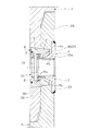
【課題】緊締用ボルトの緩み防止対策を図り、ロックピンの抜け落ちを防止できるケーシングの接続構造を提供する。【解決手段】上下ケーシング1,1の接続端部2A,2Bのうち内側接続端部2Aには周方向所要間隔で内方へ向い径の小さくなるテーパ孔3が穿設され、テーパ孔3の内端側にナット4が固着され、外側接続端部には内側接続端部2Aのテーパ孔3と対応する位置にテーパ孔5が穿設され、内外両接続端部2A,2Bの両テーパ孔3,5に中空状のロックピン6が嵌合され、ロックピン6には、内周側に突設した内向きフランジ部7と外端部に設けた抜止部材8との間に離脱不能に挿入された外向きフランジ部9を有する緊締用ボルト10が挿通され、緊締用ボルト10がナット10に螺合されると共に、内向きフランジ部7と外向きフランジ部9との間に緩み止めワッシャー11が介装される。【選択図】図1To provide a casing connection structure capable of preventing loosening of a lock pin by taking measures to prevent loosening of tightening bolts. A tapered hole 3 is formed in the inner connection end 2A out of the connection ends 2A and 2B of the upper and lower casings 1 and 1 at a required interval in the circumferential direction. A nut 4 is fixed to the inner end side, a tapered hole 5 is formed at a position corresponding to the tapered hole 3 of the inner connection end 2A at the outer connection end, and both tapered holes of the inner and outer connection ends 2A and 2B are formed. 3 and 5 are fitted with hollow lock pins 6, and the lock pins 6 cannot be detached between an inward flange portion 7 projecting on the inner peripheral side and a retaining member 8 provided on the outer end portion. The tightening bolt 10 having the inserted outward flange portion 9 is inserted, the tightening bolt 10 is screwed into the nut 10, and the locking washer is provided between the inward flange portion 7 and the outward flange portion 9. 11 is interposed. [Selection] Figure 1

Description

本考案は、基礎工法に使用されるケーシングの接続構造に関するもので、地盤中に貫入される先のケーシングの上端部に後続のケーシングの下端部を接続するのに適用される接続構造に関する。   The present invention relates to a connection structure of a casing used in a foundation method, and relates to a connection structure applied to connect a lower end portion of a succeeding casing to an upper end portion of a previous casing penetrating into the ground.

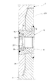
従来のケーシングの接続構造として、特許公報等の具体的な特許文献を挙げることはできないが、従来使用されているケーシング接続構造は、図3に示すように、互いに嵌合して接続される上下ケーシング1,1の接続端部2A,2Bのうち内側接続端部2Aには周方向所要間隔おきに内方に向い径の小さくなるテーパ孔13を設け、このテーパ孔13の内端側にナット15を固着し、外側接続端部2Bには内側接続端部2Aのテーパ孔13と対応する位置にそのテーパ孔13に合致するテーパ孔14を設け、これら内外両接続端部2A,2Bの両テーパ孔13,14に亘って中空状のロックピン16を嵌合し、このロックピン16には、その内周側に突設した内向きフランジ部17と外端部に固着した抜止部材18との間に離脱不能に挿入された外向きフランジ部19を有する緊締用ボルト20を挿通して、このボルト20をナット15に螺合し、このボルト20を緊締することによりボルト20の外向きフランジ部19でロックピン16の内向きフランジ部17を内方へ押圧して、ロックピン16をテーパ孔13,14に圧嵌するようにしたものである。   As a conventional casing connection structure, specific patent documents such as patent gazettes cannot be cited, but the conventionally used casing connection structure is an upper and lower part that are fitted and connected to each other as shown in FIG. Of the connecting end portions 2A and 2B of the casings 1 and 1, the inner connecting end portion 2A is provided with a tapered hole 13 having a diameter that decreases inwardly at every required interval in the circumferential direction, and a nut is formed on the inner end side of the tapered hole 13. 15 is provided in the outer connection end 2B at a position corresponding to the taper hole 13 of the inner connection end 2A, and a tapered hole 14 that matches the taper hole 13 is provided, and both the inner and outer connection ends 2A and 2B are provided. A hollow lock pin 16 is fitted over the taper holes 13, 14. The lock pin 16 has an inward flange portion 17 projecting on the inner peripheral side thereof and a retaining member 18 fixed to the outer end portion. Inseparably inserted between The tightening bolt 20 having the outward flange portion 19 is inserted, the bolt 20 is screwed into the nut 15, and the bolt 20 is tightened to tighten the lock pin 16 at the outward flange portion 19 of the bolt 20. The lock pin 16 is press-fitted into the taper holes 13 and 14 by pressing the inward flange portion 17 inward.

上記のようなケーシング接続構造によると、ケーシング1の打ち込み中に緊締用ボルト20が振動等により緩んで、ロックピン16が抜け落ちることがあった。通常、ケーシング接続端部の内側接続端部2Aと外側接続端部2Bとにはロックピン16を10数本使用しているが、ひどい時には全てのロックピン16が抜け落ち、ケーシング1を引き上げた時には、抜け落ちたロックピン16のあるケーシング1より下の部分が地中に取り残される事故が起きていた。   According to the casing connection structure as described above, the fastening bolt 20 may be loosened by vibration or the like while the casing 1 is driven, and the lock pin 16 may fall off. Normally, ten or more lock pins 16 are used at the inner connection end 2A and the outer connection end 2B of the casing connection end. However, when the casing 1 is lifted up when all the lock pins 16 have fallen off in a severe case. There was an accident in which the part below the casing 1 with the lock pin 16 dropped out was left in the ground.

本考案は、上記の課題に鑑み、緊締用ボルトの緩み防止対策を図って、ロックピンの抜け落ちを防止するようにしたケーシングの接続構造を提供することを目的とする。   In view of the above problems, an object of the present invention is to provide a casing connection structure in which a locking bolt is prevented from coming off by taking measures to prevent a tightening bolt from loosening.

上記課題を解決するための手段を、後述する実施形態の参照番号を付して説明すると、互いに嵌合して接続される上下ケーシング1,1の接続端部2A,2Bのうち内側接続端部2Aには周方向所要間隔で内方へ向い径の小さくなるテーパ孔3が穿設され、このテーパ孔3の内端側にナット4が固着され、外側接続端部2Bには内側接続端部2Aのテーパ孔3と対応する位置にそのテーパ孔3に合致するテーパ孔5が穿設され、これら内外両接続端部2A,2Bの両テーパ孔3,5に亙って、外周面6oをテーパとした中空状のロックピン6が嵌合され、ロックピン6には、内周側所要部に突設した内向きフランジ7と外端部に設けた抜止部材8との間に離脱不能に挿入された外向きフランジ9を有する緊締用ボルト10が挿通されると共に、緊締用ボルト10の外向きフランジ部9とロックピン6の内向きフランジ7との間に緩み止めワッシャー11が介装されていて、緊締用ボルト10が前記ナット4に螺合されてなることを特徴とする。   Means for solving the above problems will be described with reference numerals in the embodiments described later. Among the connection end portions 2A and 2B of the upper and lower casings 1 and 1 connected to each other, the inner connection end portions 2A is provided with a tapered hole 3 whose diameter decreases inward at a required interval in the circumferential direction, and a nut 4 is fixed to the inner end side of the tapered hole 3, and an inner connection end portion is provided on the outer connection end portion 2B. A tapered hole 5 that matches the tapered hole 3 is formed at a position corresponding to the tapered hole 3 of 2A, and the outer peripheral surface 6o is formed over both the tapered holes 3 and 5 of both the inner and outer connection end portions 2A and 2B. A tapered hollow lock pin 6 is fitted, and the lock pin 6 cannot be detached between an inward flange 7 projecting from a required portion on the inner peripheral side and a retaining member 8 provided at the outer end portion. The fastening bolt 10 having the inserted outward flange 9 is inserted and A loosening washer 11 is interposed between the outward flange portion 9 of the tightening bolt 10 and the inward flange 7 of the lock pin 6, and the tightening bolt 10 is screwed into the nut 4. Features.

請求項2は、請求項1に記載のケーシングの接続構造において、緩み止めワッシャー11は、2枚1組のワッシャー部材22,22により構成され、その噛み合い面にクサビ形状のカム22aが形成されていて、そのカム22aのクサビ角度αが緊締用ボルト10のネジ角度βより大きく設定されているクサビロックワッシャー21からなることを特徴とする。   According to a second aspect of the present invention, in the casing connection structure according to the first aspect, the locking washer 11 is composed of a set of two washer members 22, 22, and a wedge-shaped cam 22 a is formed on the meshing surface thereof. The wedge 22 is formed of a wedge lock washer 21 in which the wedge angle α of the cam 22a is set larger than the screw angle β of the tightening bolt 10.

請求項3は、両ワッシャー部材22,22の外側両面には、夫々放射状に歯22bが刻設されていることを特徴とする。   The third aspect of the present invention is characterized in that teeth 22b are engraved radially on both outer side surfaces of both washer members 22,22.

上記解決手段による考案の効果を、後述する実施形態の参照番号を付して説明すると、請求項1に係る考案のケーシング接続構造によれば、上下ケーシング1,1を接続するにあたり、下段側ケーシング1の上端部の内側接続端部2Aと上段側ケーシング1の下端部の外側接続端部2Bとを凹凸嵌合して、内側接続端部2Aのテーパ孔3と外側接続端部2Bのテーパ孔5とが合致した状態で、テーパ孔3内端側のナット4に緊締用ボルト10を螺合すると共に、このボルト10に対し離脱不能なロックピン6をテーパ孔3,5に嵌合し、斯かる状態でボルト10を回転して緊締することにより、このボルト10の外向きフランジ部9が緩み止めワッシャー11を介してロックピン6の内向きフランジ部7を押圧し、それによりロックピン6が押されて、そのテーパ状外周面6oがテーパ孔3,5に圧嵌される。こうして上下ケーシング1,1の接続端部2A,2Bが接続された状態で一連のケーシング1を地盤中に打ち込んでいる時に、振動等で緊締用ボルト10が緩もうとしても、このボルト10が緩み止めワッシャー11によって緩みを阻止されるから、ロックピン6は両接続端部2A,2Bのテーパ孔3,5から抜け落ちることがない。   The effect of the invention by the above solution will be described with reference numerals of the embodiments described later. According to the casing connection structure of the invention according to claim 1, when connecting the upper and lower casings 1, 1, the lower casing The inner connection end 2A at the upper end of 1 and the outer connection end 2B at the lower end of the upper casing 1 are concavo-convexly fitted to form a tapered hole 3 at the inner connection end 2A and a taper hole at the outer connection end 2B. 5, the tightening bolt 10 is screwed into the nut 4 on the inner end side of the tapered hole 3, and the lock pin 6 that cannot be detached from the bolt 10 is fitted into the tapered holes 3, 5. By rotating and tightening the bolt 10 in such a state, the outward flange portion 9 of the bolt 10 presses the inward flange portion 7 of the lock pin 6 through the locking washer 11, thereby the lock pin 6. But It is, the tapered outer circumferential surface 6o is press fit into the tapered hole 3,5. Thus, when the series of casings 1 are driven into the ground with the connection ends 2A and 2B of the upper and lower casings 1 and 1 connected, even if the tightening bolt 10 is loosened due to vibration or the like, the bolt 10 is loosened. Since the looseness is prevented by the stop washer 11, the lock pin 6 does not fall out of the tapered holes 3 and 5 of both connection end portions 2A and 2B.

請求項2に記載のように、緩み止めワッシャー11がクサビロックワッシャー21からなる場合は、一方のワッシャー部材22のカム22aが他方のワッシャー部材22のカム22aを押し上げて離れようとする力が働くが、クサビ効果のためにネジピッチ以上離れず、緊締用ボルト10は緩まなくなるばかりか、クサビ効果ゆえにボルト10の張力が増加し、従ってより有効な緩み止め効果が発揮される。   As described in claim 2, when the locking washer 11 comprises the wedge lock washer 21, the cam 22a of one washer member 22 pushes up the cam 22a of the other washer member 22 to exert a force to move away. However, due to the wedge effect, the tightening bolt 10 is not separated by more than the screw pitch, and the tension of the bolt 10 is increased due to the wedge effect, so that a more effective loosening prevention effect is exhibited.

請求項3に記載のように、両ワッシャー部材22,22の外側両面に、夫々放射状に歯22bが刻設されている場合には、両ワッシャー部材22,22の外側両面の歯22bによって緊締用ボルト10が締められるに従い、この緊締用ボルト10の外向きフランジ部9の座面9a及びロックピン6の内向きフランジ部7の座面7aに食い込んで強固に固定されるから、より一層有効な緩み止め効果が発揮される。   As described in claim 3, when teeth 22b are engraved radially on both outer sides of both washer members 22, 22, tightening is performed by teeth 22b on both outer sides of both washer members 22, 22. As the bolt 10 is tightened, the fastening bolt 10 bites into the seat surface 9a of the outward flange portion 9 of the tightening bolt 10 and the seat surface 7a of the inward flange portion 7 of the lock pin 6 and is firmly fixed. The anti-loosening effect is demonstrated.

本考案に係るケーシング接続構造を示す拡大断面図である。It is an expanded sectional view showing the casing connection structure concerning the present invention. (a) はクサビロックワッシャーを示す斜視図であり、(b) はクサビロックワッシャーの原理を説明する説明図である。(a) is a perspective view which shows a wedge lock washer, (b) is explanatory drawing explaining the principle of a wedge lock washer. 従来のケーシング接続構造を示す拡大断面図である。It is an expanded sectional view which shows the conventional casing connection structure.

以下に本考案の好適な実施形態について図面を参照しながら説明すると、図1は、図3に示す従来のケーシング接続構造と同じ様に、互いに接続される上下ケーシング1,1における下段側ケーシング1の上端部内周側に内側接続端部2Aを形成し、また上段側ケーシング1の下端部外周側に外側接続端部2Bを形成し、そしてこれら内側接続端部2Aと外側接続端部2Bとを互いに凹凸嵌合して接続した接続構造を示す。尚、内側接続端部2A及び外側接続端部2Bはケーシングの上下端部に一体に形成されることもあるが、通常の場合には、内側接続端部2Aは雄ジョイントとして、また外側接続端部2Bは雌ジョイントとして、ケーシング本体部の上端部及び下端部に夫々溶接によって一体的に連結される。   A preferred embodiment of the present invention will be described below with reference to the drawings. FIG. 1 shows a lower casing 1 in upper and lower casings 1 and 1 connected to each other in the same manner as the conventional casing connecting structure shown in FIG. The inner connection end 2A is formed on the inner peripheral side of the upper end portion of the upper casing 1 and the outer connection end portion 2B is formed on the outer peripheral side of the lower end portion of the upper casing 1. The inner connection end portion 2A and the outer connection end portion 2B are connected to each other. A connection structure in which concave and convex are mutually connected is shown. The inner connection end 2A and the outer connection end 2B may be formed integrally with the upper and lower ends of the casing, but in the normal case, the inner connection end 2A is a male joint and the outer connection end. The part 2B is integrally connected to the upper end part and the lower end part of the casing main body part by welding as a female joint.

図1に示す本考案のケーシング接続構造においては、上下ケーシング1,1の接続端部2A,2Bのうち内側接続端部2Aに、周方向所要間隔おきに内方へ向い径の小さくなるテーパ孔3が穿設され、このテーパ孔3の内端側にナット4が溶接により固着され、外側接続端部2Bには、内側接続端部2Aのテーパ孔3と対応する位置にそのテーパ孔3に合致するテーパ孔5が穿設され、これら内外両接続端部2A,2Bの両テーパ孔3,5に亙って、外周面6oを前記テーパ孔3,5に嵌合可能なテーパとした中空状のロックピン6が嵌合され、このロックピン6には、ロックピン6の内周側所要部に突設した内向きフランジ部7とロックピン6の外端部に溶接により固着したリング状の抜止部材8との間に離脱不能に挿入された外向きフランジ部9を有する緊締用ボルト10が挿通されて、この緊締用ボルト10の雄ねじ部10aがナット4の雌ねじ部4aに螺合されるところまでは、図3に示す従来の接続構造と同様であるが、本考案の特徴は、ロックピン6の内向きフランジ部7と、緊締用ボルト10の外向きフランジ部9との間に、緊締用ボルト10の緩みを阻止する緩み止めワッシャー11を介装したことにある。尚、抜止部材8は、ロックピン6の外端部に対し脱着可能に取り付けることもできる。   In the casing connection structure of the present invention shown in FIG. 1, a taper hole having a diameter that decreases inward toward the inner connection end 2 </ b> A among the connection ends 2 </ b> A and 2 </ b> B of the upper and lower casings 1, 1. 3 is drilled, and a nut 4 is fixed to the inner end side of the tapered hole 3 by welding, and the outer connecting end 2B has a taper hole 3 at a position corresponding to the tapered hole 3 of the inner connecting end 2A. A matching taper hole 5 is formed, and the outer peripheral surface 6o is a taper that can be fitted into the taper holes 3 and 5 over both the taper holes 3 and 5 of both the inner and outer connection end portions 2A and 2B. A ring-shaped lock pin 6 is fitted, and the lock pin 6 has a ring-like shape fixed to the outer end portion of the lock pin 6 by welding to an inward flange portion 7 projecting from a required portion on the inner peripheral side of the lock pin 6. An outwardly-inserted hula inserted in a non-detachable manner with the retaining member 8 Until the tightening bolt 10 having the threaded portion 9 is inserted and the male threaded portion 10a of the tightening bolt 10 is screwed into the female threaded portion 4a of the nut 4, it is the same as the conventional connection structure shown in FIG. However, a feature of the present invention is that a locking washer 11 is provided between the inward flange portion 7 of the lock pin 6 and the outward flange portion 9 of the tightening bolt 10 to prevent the tightening bolt 10 from loosening. It is in the disguise. Note that the retaining member 8 can be detachably attached to the outer end portion of the lock pin 6.

上記緩み止めワッシャー11は、クサビロックワッシャー21からなる。このクサビロックワッシャー21について、図2 の(a) ,(b) を参照して説明すると、(a) はクサビロックワッシャー21を示す斜視図であり、(b) はクサビロックワッシャー21の原理を説明する説明図である。このクサビロックワッシャー21は、(a) に示すように、2枚1組のワッシャー部材22,22によって構成され、その噛み合い面にクサビ形状のカム22aが形成されていて、カム22aのクサビ角度αは、(b) に示されるように、図1の緊締用ボルト10に対応する図2の(a) の原理図に示すボルト30のネジ角度βより大きく設定されている。   The locking washer 11 includes a wedge lock washer 21. The wedge lock washer 21 will be described with reference to FIGS. 2A and 2B. FIG. 2A is a perspective view showing the wedge lock washer 21, and FIG. 2B shows the principle of the wedge lock washer 21. It is explanatory drawing demonstrated. As shown in (a), the wedge lock washer 21 is composed of a pair of washer members 22, 22, and a wedge-shaped cam 22 a is formed on the meshing surface thereof, and the wedge angle α of the cam 22 a is formed. Is set larger than the screw angle β of the bolt 30 shown in the principle diagram of FIG. 2A corresponding to the tightening bolt 10 of FIG. 1, as shown in FIG.

従って、ボルト30(緊締用ボルト10)が緩もうとすると、一方のワッシャー部材22のカム22aが他方のワッシャー部材22のカム22aを押し上げて離れようとする力が働くが、クサビ効果のためにネジピッチ以上離れない。さらに、ボルト30(緊締用ボルト10)が緩まないばかりか、クサビ効果によってボルト30の張力が増加し、ボルト30(緊締用ボルト10)のセルフロック状態になっていく。さらにまた、両ワッシャー部材22,22の外側両面には、図2の(a) に示すように、放射状に歯22bが刻設されていて、ボルト30(緊締用ボルト10)が締められるに従い、そのボルト30の座面30a及び被締付物Wに食い込んで固定されるようになっている。   Therefore, when the bolt 30 (tightening bolt 10) tries to loosen, the cam 22a of one washer member 22 pushes up the cam 22a of the other washer member 22 to release it, but because of the wedge effect No more than the screw pitch. In addition, the bolt 30 (tightening bolt 10) does not loosen, but the tension of the bolt 30 increases due to the wedge effect, and the bolt 30 (tightening bolt 10) enters a self-locking state. Furthermore, as shown in FIG. 2 (a), teeth 22b are radially engraved on both outer sides of both washer members 22, 22, and as bolts 30 (tightening bolts 10) are tightened, The bolt 30 is fixed by biting into the seating surface 30a of the bolt 30 and the article to be fastened W.

上記したような本考案のケーシング接続構造において、ロックピン6に緊締用ボルト10を組み込むには、中空状のロックピン6内にその外端側から緩み止めワッシャー11を挿入した後、このロックピン6内にその外端側から緊締用ボルト10を挿通して、このボルト10の外向きフランジ部9で緩み止めワッシャー11をロックピン6の内向きフランジ部7に押し付け、これによってロックピン6の内向きフランジ部7と、ボルト10の外向きフランジ部9との間に緩み止めワッシャー11を介装した状態とする。この後、ロックピン6の外端部に抜止部材8を溶接して固着することにより、ボルト10の外向きフランジ部9をロックピン6に対し抜け出し不能とする。また、ナット4は、その外向きフランジ部4oを内側接続端部2Aの内周側凹段部23に溶接して固着する。尚、抜止部材8はロックピン6の外端部に脱着可能に取り付けてもよい。   In the casing connection structure of the present invention as described above, in order to incorporate the tightening bolt 10 into the lock pin 6, after the lock washer 11 is inserted into the hollow lock pin 6 from the outer end side, this lock pin 6 is inserted. 6, the tightening bolt 10 is inserted from the outer end side thereof, and the locking flange washer 11 is pressed against the inward flange portion 7 of the lock pin 6 by the outward flange portion 9 of the bolt 10. It is assumed that a locking washer 11 is interposed between the inward flange portion 7 and the outward flange portion 9 of the bolt 10. Thereafter, the retaining member 8 is welded and fixed to the outer end portion of the lock pin 6 so that the outward flange portion 9 of the bolt 10 cannot be removed from the lock pin 6. Further, the nut 4 is fixed by welding the outward flange portion 4o to the inner peripheral concave step portion 23 of the inner connection end portion 2A. The retaining member 8 may be detachably attached to the outer end portion of the lock pin 6.

しかして、上下ケーシング1,1を接続するにあたり、下段側ケーシング1の上端部の内側接続端部2Aと上段側ケーシング1の下端部の外側接続端部2Bとを凹凸嵌合して、内側接続端部2Aのテーパ孔3と外側接続端部2Bのテーパ孔5とが合致した状態で、テーパ孔3の内端側に固着されたナット4に緊締用ボルト10を螺合すると共に、このボルト10に対し離脱不能なロックピン6のテーパ状外周面6oをテーパ孔3,5に嵌合し、この状態で、緊締用ボルト10の基端部に設けてある工具係合凹部24に回転操作用工具を係合し、ボルト10を回転して緊締することにより、このボルト10の外向きフランジ部9が緩み止めワッシャー11を介してロックピン6の内向きフランジ部7を押圧し、それによりロックピン6が内方へ押されて、そのテーパ状外周面6oがテーパ孔3,5に圧嵌される。   Thus, when connecting the upper and lower casings 1, 1, the inner connection end 2 </ b> A at the upper end of the lower casing 1 and the outer connection end 2 </ b> B at the lower end of the upper casing 1 are indented and connected inwardly. In a state where the tapered hole 3 of the end portion 2A and the tapered hole 5 of the outer connecting end portion 2B are matched, a tightening bolt 10 is screwed into the nut 4 fixed to the inner end side of the tapered hole 3, and this bolt 10, the tapered outer peripheral surface 6 o of the lock pin 6, which cannot be removed with respect to 10, is fitted into the tapered holes 3, 5. In this state, the tool engaging recess 24 provided at the base end of the tightening bolt 10 is rotated. By engaging the working tool and rotating and tightening the bolt 10, the outward flange portion 9 of this bolt 10 presses the inward flange portion 7 of the lock pin 6 via the locking washer 11, thereby Lock pin 6 is inward It is, the tapered outer circumferential surface 6o is press fit into the tapered hole 3,5.

こうして上下ケーシング1,1の接続端部2A,2Bが接続された状態で一連のケーシング1を地盤中に打ち込んでいる時に、振動などで緊締用ボルト10が緩もうとすると、クサビロックワッシャー21を構成する一方のワッシャー部材22のカム22aが他方のワッシャー部材22のカム22aを押し上げて離れようとする力が働くが、クサビ効果のためにネジピッチ以上離れなくなって、緊締用ボルト10は緩まないばかりか、クサビ効果ゆえにボルト10の張力が増加し、また両ワッシャー部材22,22の外側両面に刻設されている歯22bによってボルト10が締められるに従い、このボルト10の外向きフランジ部9の座面9a及びロックピン6の内向きフランジ部7の座面7aに食い込んで固定される。このようにクサビロックワッシャー21(緩み止めワッシャー11)によって緊締用ボルト10の緩みが阻止されるため、ロックピン6の両接続端部2A,2Bのきテーパ孔3,5から抜け落ちることがなく、従来のようにケーシング1が地中に取り残される、という事故を回避することができる。   In this way, when the series of casings 1 are driven into the ground with the connection ends 2A and 2B of the upper and lower casings 1 and 1 connected, if the tightening bolt 10 is loosened due to vibration or the like, the wedge lock washer 21 is moved. The cam 22a of one of the washer members 22 that constitutes pushes up the cam 22a of the other washer member 22 to release the force. However, due to the wedge effect, the cam bolt 22a is no longer separated from the screw pitch, and the tightening bolt 10 is not loosened. Alternatively, the tension of the bolt 10 increases due to the wedge effect, and as the bolt 10 is tightened by the teeth 22b engraved on both outer sides of the washer members 22, 22, the seat of the outward flange portion 9 of the bolt 10 is tightened. The surface 9a and the seating surface 7a of the inward flange portion 7 of the lock pin 6 are fixed by biting. In this way, the wedge lock washer 21 (loosening prevention washer 11) prevents the tightening bolt 10 from being loosened, so that it does not fall out of the tapered holes 3 and 5 at both connecting ends 2A and 2B of the lock pin 6. It is possible to avoid an accident that the casing 1 is left behind in the ground as in the past.

緩み止めワッシャー11としては、この実施形態に示したクサビロックワッシャー21に限定されるものではないが、このクサビロックワッシャー21は、緊締用ボルト10に対する最も有効な緩み止め効果を発揮することができる。   The locking washer 11 is not limited to the wedge lock washer 21 shown in this embodiment, but the wedge lock washer 21 can exhibit the most effective locking effect for the tightening bolt 10. .

1 ケーシング
2A ケーシングの内側接続端部
2B ケーシングの外側接続端部
3 内側接続端部のテーパ孔
4 ナット
5 外側接続端部のテーパ孔
6 ロックピン
7 ロックピンの内向きフランジ部
8 抜止部材
9 緊締用ボルトの外向きフランジ部
10 緊締用ボルト
11 緩み止めワッシャー
21 クサビロックワッシャー
22 ワッシャー部材
22a クサビ形状カム
22b 歯
DESCRIPTION OF SYMBOLS 1 Casing 2A Inner connection end 2B of casing Outer connection end 3 of casing Casing hole 4 of inner connection end 4 Nut 5 Taper hole 6 of outer connection end Lock pin 7 Inward flange part 8 of lock pin Locking member 9 Tightening Bolt outward flange 10 Tightening bolt 11 Loosening lock washer 21 Wedge lock washer 22 Washer member 22a Wedge cam 22b Teeth

Claims (3)

互いに嵌合して接続される上下ケーシングの接続端部のうち内側接続端部には周方向所要間隔で内方へ向い径の小さくなるテーパ孔が穿設され、このテーパ孔の内端側にナットが固着され、外側接続端部には内側接続端部のテーパ孔と対応する位置にそのテーパ孔に合致するテーパ孔が穿設され、これら内外両接続端部の両テーパ孔に亙って、外周面をテーパとした中空状のロックピンが嵌合され、ロックピンには、内周側所要部に突設した内向きフランジ部と外端部に設けた抜止部材との間に離脱不能に挿入された外向きフランジ部を有する緊締用ボルトが挿通されると共に、緊締用ボルトの外向きフランジ部とロックピンの内向きフランジ部との間に緩み止めワッシャーが介装されていて、緊締用ボルトが前記ナットに螺合されてなるケーシングの接続構造。   Of the connection ends of the upper and lower casings that are fitted and connected to each other, a taper hole having a diameter that decreases inward at a required interval in the circumferential direction is formed in the inner connection end, and is formed on the inner end side of the taper hole. The nut is fixed, and the outer connection end is provided with a taper hole that matches the taper hole at a position corresponding to the taper hole of the inner connection end, and extends over both the taper holes of the inner and outer connection ends. A hollow lock pin with a tapered outer peripheral surface is fitted, and the lock pin cannot be detached between an inward flange portion projecting from a required portion on the inner peripheral side and a retaining member provided at the outer end portion. A tightening bolt having an outward flange portion inserted into the bolt is inserted, and a locking washer is interposed between the outward flange portion of the tightening bolt and the inward flange portion of the lock pin. The bolt is screwed into the nut. Connection structure Thing. 緩み止めワッシャーは、2枚1組のワッシャー部材により構成され、その噛み合い面にクサビ形状のカムが形成されていて、そのカムのクサビ角度が緊締用ボルトのネジ角度より大きく設定されているクサビロックワッシャーからなる請求項1に記載のケーシングの接続構造。   The locking washer is composed of a set of two washer members, a wedge-shaped cam is formed on the meshing surface, and the wedge angle of the cam is set larger than the screw angle of the tightening bolt. The casing connection structure according to claim 1, comprising a washer. 両ワッシャー部材の外側両面には、夫々放射状に歯が刻設されている請求項2に記載のケーシングの接続構造。   3. The casing connection structure according to claim 2, wherein teeth are engraved radially on both outer side surfaces of both washer members.
JP2011000875U 2011-02-21 2011-02-21 Casing connection structure Expired - Lifetime JP3167659U (en)

Priority Applications (1)

Application Number Priority Date Filing Date Title
JP2011000875U JP3167659U (en) 2011-02-21 2011-02-21 Casing connection structure

Applications Claiming Priority (1)

Application Number Priority Date Filing Date Title
JP2011000875U JP3167659U (en) 2011-02-21 2011-02-21 Casing connection structure

Publications (1)

Publication Number Publication Date
JP3167659U true JP3167659U (en) 2011-05-12

Family

ID=54878730

Family Applications (1)

Application Number Title Priority Date Filing Date
JP2011000875U Expired - Lifetime JP3167659U (en) 2011-02-21 2011-02-21 Casing connection structure

Country Status (1)

Country Link
JP (1) JP3167659U (en)

Cited By (2)

* Cited by examiner, † Cited by third party
Publication number Priority date Publication date Assignee Title
JP2014080772A (en) * 2012-10-16 2014-05-08 Sanwa Kiko Kk Connection structure of casing
CN114704615A (en) * 2022-04-06 2022-07-05 中国第一汽车股份有限公司 Creep-resistant transmission shell and assembly process

Similar Documents

Publication Publication Date Title
JP6437313B2 (en) Locking special double nut
US20150184686A1 (en) Bolt
CA2346591C (en) Screw member
JP5231656B2 (en) bolt
KR20140030308A (en) Attachment arrangement for composite wheels
JP3167659U (en) Casing connection structure
JP2017141853A (en) Method for manufacturing fastener comprising bolt and nut
KR20150140895A (en) Anti-loose nut
JP2018040376A (en) Fastener
JP3155204U (en) Eccentric lock nut
KR200451199Y1 (en) Electrical connection connector prevents loosening and easy unlocking
JP6583721B2 (en) Double nut and manufacturing method thereof
US20050120821A1 (en) Bolt lock
JP5712408B2 (en) Locking bolt
AU2008200632B2 (en) Locking washer
JP2015227721A (en) Looseness prevention structure for bolt and nut
JP3153130U (en) Double nut
JP3244958U (en) automatic fixing screw
KR20090005484U (en) Loosen wrench bolts
JP5249087B2 (en) Locking bolt
JP2005127429A (en) Screw fastening body having loosing prevention property and fastening release apparatus used therefor
CN216143049U (en) A longitudinal tooth type anti-loosening fastening component
US20240253391A1 (en) Attachment arrangement for composite wheels
JP3103067B2 (en) Nut removal prevention structure
JP5782421B2 (en) Casing connection structure

Legal Events

Date Code Title Description
R150 Certificate of patent or registration of utility model

Ref document number: 3167659

Country of ref document: JP

Free format text: JAPANESE INTERMEDIATE CODE: R150

Free format text: JAPANESE INTERMEDIATE CODE: R150

FPAY Renewal fee payment (event date is renewal date of database)

Free format text: PAYMENT UNTIL: 20140413

Year of fee payment: 3

R250 Receipt of annual fees

Free format text: JAPANESE INTERMEDIATE CODE: R250

R250 Receipt of annual fees

Free format text: JAPANESE INTERMEDIATE CODE: R250

R250 Receipt of annual fees

Free format text: JAPANESE INTERMEDIATE CODE: R250

R250 Receipt of annual fees

Free format text: JAPANESE INTERMEDIATE CODE: R250

R250 Receipt of annual fees

Free format text: JAPANESE INTERMEDIATE CODE: R250

R250 Receipt of annual fees

Free format text: JAPANESE INTERMEDIATE CODE: R250

R250 Receipt of annual fees

Free format text: JAPANESE INTERMEDIATE CODE: R250

EXPY Cancellation because of completion of term