JP3200919U - Self-luminous safety waistcoat - Google Patents
Self-luminous safety waistcoat Download PDFInfo
- Publication number
- JP3200919U JP3200919U JP2015004397U JP2015004397U JP3200919U JP 3200919 U JP3200919 U JP 3200919U JP 2015004397 U JP2015004397 U JP 2015004397U JP 2015004397 U JP2015004397 U JP 2015004397U JP 3200919 U JP3200919 U JP 3200919U
- Authority
- JP
- Japan
- Prior art keywords
- reflective marker
- light emitting
- self
- band
- covered
- Prior art date
- Legal status (The legal status is an assumption and is not a legal conclusion. Google has not performed a legal analysis and makes no representation as to the accuracy of the status listed.)
- Expired - Lifetime
Links
Images





Landscapes
- Professional, Industrial, Or Sporting Protective Garments (AREA)
Abstract
【課題】交通整理や検問などを行う警察官を初め、道路工事の警備員などが着用する断線しにくく耐久性の高い自発光式の安全チョッキを提供する。【解決手段】第1反射標識帯B1に付属の電源ボックス14から多数の発光ダイオード12へ給電する2本1組の被覆電線18が、第2反射標識帯B2における左右何れか一方の前立て部6から肩部7を経て同じ一方の後立て部の下端に一旦到達し、更にその下端から上方へUターンして、左右何れか他方の後立て部と肩部を経て同じ他方の前立て部の下端付近まで到達することになる長いシームレスの連続一本物として設置されるとともに、被覆電線の保護被膜を剥離した裸線部と、各発光ダイオードのリード線とが通電状態にハンダ付けされている。【選択図】図1PROBLEM TO BE SOLVED: To provide a self-luminous safety waistcoat that is hard to be disconnected and highly durable, which is worn by police officers who conduct traffic control and inspections, as well as road construction guards and the like. SOLUTION: A set of two covered wires 18 for feeding power to a large number of light-emitting diodes 12 from a power supply box 14 attached to a first reflective marker strip B1 is provided on either the left or right placket 6 in the second reflective marker strip B2. To the lower end of the same one prop from the lower end of the same, and further U-turns from the lower end to the lower end of the other prop. It is installed as a long, continuous single piece that reaches the vicinity, and the bare wire portion from which the protective coating of the coated electric wire is peeled off and the lead wires of the respective light emitting diodes are soldered in an energized state. [Selection] Figure 1
Description
本考案は夜間に交通整理や交通事故の処理、検問などを行う警察官を初め、夜間の道路工事に立ち会う警備員などが着用する自発光式の安全チョッキに関する。 The present invention relates to a self-luminous safety waistcoat worn by police officers who conduct traffic control, traffic accident handling, and inspections at night, as well as guards who are present at night road construction.
一般に、チョッキ本体の左肩部と右肩部から前立て部の下端と後立て部の下端に掛けて、ほぼV字形に縫い付けられた反射標識帯に、複数の発光ダイオード(LED)が点在分布状態に植え付けられ、その発光ダイオードの点滅によって、夜間の車両運転者にチョッキ着用者の存在を知らせる自発光式の安全チョッキは、例えば特許文献1〜4に記載のとおり公知である。
In general, a plurality of light emitting diodes (LEDs) are scattered in a reflective sign band that is sewn in a substantially V-shape from the left shoulder and right shoulder of the waistcoat to the lower end of the front stand and the lower end of the back stand. Self-luminous safety waistcoats that are planted in a state and inform the vehicle driver at night by the flashing of the light-emitting diodes are known as disclosed in, for example,
ところが、既に市販されている公知の安全チョッキでは、カットされた2本1組の被覆電線を介して、隣り合う発光ダイオード(LED)同士が接続されており、その被覆電線の保護被膜を剥離した裸線部と、発光ダイオードのリード線とをハンダ付けした個所が数多く点在し、これらの個所が言わば継ぎ目となるため、しかもそのハンダ付けした個所(継ぎ目)はそのままの放置状態にあり、接着剤などによって被覆固定されてもいないため、その付け根部分から自由に屈曲変形し、断線事故を起しやすい。 However, in a known safety vest that is already on the market, adjacent light emitting diodes (LEDs) are connected to each other via a pair of cut two covered wires, and the protective coating of the covered wires is peeled off. There are many places where the bare wire and the lead wires of the light emitting diodes are soldered, and these places become seams, so the soldered places (seams) are left as they are and bonded. Since it is not covered and fixed by an agent or the like, it is easily bent and deformed from its base portion, and a disconnection accident is likely to occur.
特に、安全チョッキの着用者が夜間作業中に、荷物を両手で抱えて持ち運んだり、車両の底側へ腹這いの姿勢で潜り込んだりすると、そのチョッキ本体の前立て部に並ぶ反射標識帯が、繰り返し摺擦されたり、皺寄り変形されたりするため、これに付属している上記被覆電線も追従して、早期に断線してしまうのである。 In particular, when a safety vest wearer carries a baggage with both hands while working at night or sinks into the bottom of the vehicle in a prone posture, the reflective sign strips lined up on the front of the vest body repeatedly slide. Since it is rubbed or deformed near the heel, the above-mentioned covered electric wire attached to it also follows and breaks early.
更に、上記反射標識帯に植え付けられる発光ダイオード(LED)としても、その光軸方向(前後方向)から見た場合の輝度は高いが、横方向から見た場合の輝度は低く、車両運転者からの視認性に劣るため、チョッキ着用者の安全性を未だ充分に確保することができない。 Further, the light-emitting diode (LED) planted in the reflective sign band has a high luminance when viewed from the optical axis direction (front-rear direction), but is low when viewed from the lateral direction. Therefore, the waistcoat wearer's safety cannot be sufficiently ensured.
本考案はこのような諸問題の解決を目的としており、その目的を達成するめに請求項1では胴部を包囲する開閉可能な一文字形の第1反射標識帯と、
The present invention aims to solve these various problems, and in order to achieve the object, the first reflective sign strip of a single-letter shape that can be opened and closed and surrounds the trunk portion is defined in
その第1反射標識帯に連結された左右一対の前立て部から両肩部を経て、同じく第1反射標識帯に連結された左右一対の後立て部まで連続するほぼV字形の第2反射標識帯と、 A substantially V-shaped second reflection sign band that continues from the pair of left and right front standing parts connected to the first reflection sign band through both shoulders to the pair of left and right rear standing parts similarly connected to the first reflection sign band. When,
その第2反射標識帯に沿って適当な間隔おきに点在分布された多数の発光ダイオードとを備えた自発光式の安全チョッキにおいて、 In a self-luminous safety waistcoat comprising a number of light emitting diodes scattered at appropriate intervals along the second reflective marker band,
上記第1反射標識帯又は第2反射標識帯に付属の電源から発光ダイオードへ給電する2本1組の被覆電線が、上記第2反射標識帯における左右何れか一方の前立て部から肩部を経て同じ一方の後立て部の下端に一旦到達し、更にその下端から上方へUターンすることにより、左右何れか他方の後立て部と肩部を経て同じ他方の前立て部の下端付近まで到達することになる長いシームレスの連続一本物として、 A set of two covered wires for supplying power to the light emitting diodes from the power supply attached to the first reflective marker band or the second reflective marker band passes through the shoulder from the left or right foremost part of the second reflective marker band. Once reaching the lower end of the same one of the rear standing parts, and further making a U-turn upward from the lower end, it reaches the vicinity of the lower end of the same other standing part through the left and right rear raising parts and shoulders. As a long seamless continuous single
その被覆電線の保護被膜を剥離した裸線部と、各発光ダイオードのリード線とが通電状態にハンダ付けされていることを特徴とする。 The bare wire portion from which the protective coating of the covered electric wire is peeled off and the lead wires of the respective light emitting diodes are soldered in an energized state.
又、請求項2では被覆電線の裸線部と各発光ダイオードのリード線とのハンダ付け部が、シリコン系接着剤での被覆状態に固定されていることを特徴とする。 According to a second aspect of the present invention, the soldered portion between the bare wire portion of the covered electric wire and the lead wire of each light emitting diode is fixed in a covered state with a silicon-based adhesive.
請求項3では被覆電線が第2反射標識帯における左右一対の前立て部を通る位置だけに、二重回路となる別個の短かい第2被覆電線が追加接続されていることを特徴とする。 According to a third aspect of the present invention, a separate short second covered electric wire serving as a double circuit is additionally connected only to a position where the covered electric wire passes through the pair of left and right plackets in the second reflective marker band.
請求項4では第2反射標識帯の表面から膨出する各発光ダイオードの頭部がその第2反射標識帯の表側から、裏当て状態にある絶縁座板へ差し込み固定された透明な光拡散カバーの円錐ヘッドによって、包囲状態に保たれていることを特徴とする。 5. A transparent light diffusing cover in which the heads of the respective light-emitting diodes bulging from the surface of the second reflective marker strip are inserted and fixed from the front side of the second reflective marker strip to the insulating seat plate in the backing state. It is characterized by being kept in an enclosed state by a conical head.
更に、請求項5ではチョッキ本体の表面と、その表面へ縁取り状態に縫い付けられた第2反射標識帯の裏面との相互間に、各ハンダ付け部のシリコン系接着剤を更に裏側からすべて被覆する一定帯幅の長い粘着性スポンジテープ材が介挿設置されていることを特徴とする。
Further, in
請求項1の構成によれば、正・背面視のほぼV字形をなす第2反射標識帯に点在分布する多数の発光ダイオード(LED)へ、その第2反射標識帯又は第1反射標識帯に付属の電源から給電する2本1組の被覆電線が、その途中での一切カットされておらず、上記第2反射標識帯における延べ長さの全体に及ぶシームレスな連続一本物として、その被覆電線の保護被膜を剥離した裸線部と、各発光ダイオードのリード線とが立体交叉した接点での通電状態にハンダ付けされているため、その通電状態が著しく安定し、ハンダ付け部の根元から被覆電線の断線するおそれがない。 According to the configuration of the first aspect, the second reflective marker strip or the first reflective marker strip is distributed to a large number of light emitting diodes (LEDs) scattered in the second reflective marker strip that is substantially V-shaped when viewed from the front and back. A set of two covered wires that are fed from the power supply attached to the cable is not cut at all along the way, but as a seamless continuous single piece covering the entire length of the second reflective marker band, Since the bare wire part from which the protective coating of the wire has been peeled off and the lead wires of each light-emitting diode are soldered to the energized state at the contact point where the three-dimensionally intersected, the energized state is remarkably stable, and from the root of the soldered part There is no risk of breakage of the covered wire.
その場合、請求項2の構成を採用するならば、上記ハンダ付け部の各個が裏側からシリコン系接着剤での被覆状態に固定されているため、上記被覆電線の不正な変形とこれに起因する断線事故をますます確実に予防することができる。
In that case, if the configuration of
特に、請求項3の構成を採用するならば、上記第2反射標識帯における摺擦や皺寄り変形などが起りやすい前立て部の位置だけは、その位置を通る連続一本物の長い上記被覆電線のほかに、これとの二重回路を形成する別個な短かい第2被覆電線が追加接続されてもいるため、その長い(第1)被覆電線が万一断線したとしても、別個な第2被覆電線によって発光ダイオードへの通電を支障なく行えるのであり、耐用性がますます向上する。
In particular, if the configuration of
又、請求項4の構成を採用するならば、上記第2反射標識帯の表面から膨出する状態に取り付けられている各発光ダイオードの頭部が、透明な光拡散カバーの円錐ヘッドによって包囲された状態にあり、各発光ダイオードの発光がその光拡散カバーによって広角度に拡散されるため、チョッキ着用者の前後方向からはもとより、その横方向(左右方向)から見た場合の高い輝度・視認性を得られ、チョッキ着用者の安全性を充分に確保することができる。
If the configuration of
更に、請求項5の構成を採用するならば、第2反射標識帯の裏面とその第2反射標識帯が縫い付けられたチョッキ本体の表面との相互間に、一定帯幅の粘着性スポンジテープ材が上記被覆電線とほぼ同じ長さだけ介挿設置されており、これによって多数の点在分布状態にある各ハンダ付け部のシリコン系接着剤が、すべて裏側から被覆されているため、そのスポンジテープ材が上記第2反射標識帯と延いてはチョッキ本体に曲げ抵抗を与えることとなり、その結果として被覆電線の断線事故をますます完全に予防することができる。
Furthermore, if the structure of
以下、図面に基いて本考案の実施形態を詳述すると、その安全チョッキの概略全体を示した図1〜7において、(V)はメッシュ状やその他の通気性を有する軽い生地から作成されたチョッキ本体であり、その後身頃(1r)が着用者の背中を全体的に覆う大きさ・形状を有するに比し、前身頃(1f)は対称なほぼL字形をなす左前身頃(1f−L)と右前身頃(1f−R)との一対から成るに過ぎず、胸の中央位置が開放した形態になっている。そのチョッキ本体(V)へ縁取り状態に縫い付けられたバイアステープには、図示符号を省略してある。 Hereinafter, the embodiment of the present invention will be described in detail with reference to the drawings. In FIGS. 1 to 7, which shows an overall outline of the safety vest, (V) is made from a mesh-like or other light fabric having air permeability. The front body (1f) has a symmetrical L-shaped front left body (1f-L) as compared to the waistcoat body and the body (1r) having a size and shape that covers the entire back of the wearer. And the right front body (1f-R) are only a pair, and the center position of the chest is open. The reference numeral is omitted from the bias tape sewn to the vest body (V) in an edged state.
つまり、左前身頃(1f−L)と右前身頃(1f−R)における対称なほぼL字形の縦辺は、一定帯幅(W1)(例えば約9cm)の肩ベルト状前立て面(2)(2)として、正面視のほぼV字形に起立しており、その上端部の肩面を経て後身頃(1r)に連続している。又、同じく対称なほぼL字形の横辺は一定帯幅(W2)(例えば約9.5cm)の前胴面(3)(3)として、後身頃(1r)との連続状態にある。 That is, the symmetrical substantially L-shaped vertical sides of the left front body (1f-L) and the right front body (1f-R) are shoulder belt-like front surfaces (2) (2) having a constant band width (W1) (for example, about 9 cm). ) Standing up in a substantially V shape in front view, and continuing to the back body (1r) through the shoulder surface of the upper end. Similarly, the symmetrical substantially L-shaped lateral side is in a continuous state with the back body (1r) as the front torso surfaces (3) and (3) having a constant band width (W2) (for example, about 9.5 cm).
(4)(4)は左前身頃(1f−L)と右前身頃(1f−R)との前胴面(3)(3)同士を、その中央位置の召し合わせ部において係止する雌雄一対の面ファスナーであるが、左前身頃(1f−L)と右前身頃(1f−R)とを開閉できるならば、その面ファスナー(4)(4)に代るスライドファスナーやハトメホック、その他の係止具を採用しても良い。 (4) (4) is a pair of male and female locking the front torso surfaces (3) and (3) of the left front body (1f-L) and the right front body (1f-R) at the summing portion at the center position. If it is a hook-and-loop fastener, and the left front body (1f-L) and the right front body (1f-R) can be opened and closed, slide fasteners, eyelet hooks, and other fasteners that replace the hook-and-loop fasteners (4) and (4) May be adopted.
その場合、左前身頃(1f−L)と右前身頃(1f−R)の前胴面(3)(3)は各々後身頃(1r)の対応的な後胴面(図示符号省略)と胴廻り調整用の面ファスナー(5L)(5L)(5R)(5R)を介して係止されており、その雌雄一対づつを着脱自在に係止することによって、着用者の胴部に応じた寸法の調整を行えるようになっている。その係止具としては無段階の調整を行える点で、面ファスナーが最適である。 In that case, the front torso surfaces (3) and (3) of the left front body (1f-L) and the right front body (1f-R) respectively correspond to the corresponding back torso surface (not shown) of the back body (1r) and the waistline adjustment. The surface fastener (5L) (5L) (5R) (5R) is used, and the dimension according to a wearer's trunk | drum is adjusted by detachably locking the male and female pair one by one. Can be done. A hook-and-loop fastener is the most suitable as the locking tool because it can be adjusted steplessly.
(B1)は上記左前身頃(1f−L)と右前身頃(1f−R)の前胴面(3)(3)から後身頃(1r)の対応的な後胴面に沿う言わば一文字形(横置き状態)の配列として、縁取り状態に縫い付けられた一定幅(W3)(例えば約6cm)の第1反射標識帯であり、着用者の胴部を包囲することになるが、上記召し合わせ部の面ファスナー(4)(4)によって開閉することもできる。その第1反射標識帯(B1)の一定幅(W3)は上記前胴面(3)(3)の一定帯幅(W2)よりも若干狭い。 (B1) is a so-called one-letter shape (horizontal) along the corresponding rear torso surface of the left body (1f-L) and the front torso surface (3) (3) of the right front body (1f-R) to the back body (1r). As the arrangement of the laying state, it is a first reflective sign band having a constant width (W3) (for example, about 6 cm) sewn in the edging state and surrounds the wearer's torso. The hook and loop fasteners (4) and (4) can also be opened and closed. The fixed width (W3) of the first reflective marker band (B1) is slightly narrower than the fixed band width (W2) of the front trunk surfaces (3) and (3).
又、(B2)(B2)は上記左前身頃(1f−L)と右前身頃(1f−R)の前立て面(2)(2)よりも若干狭い一定幅(W4)(例えば約6cm)を備えた左右一対の第2反射標識帯であり、その上記第1反射標識帯(B1)に連結された前立て部(6)(6)から両肩部(7)(7)を経て後身頃(1r)に向かい、その後身頃(1r)の後胴面にある第1反射標識帯(B1)に連結された後立て部(8)(8)まで連続する図1、2のような正・背面視のほぼV字形として、上記左前身頃(1f−L)と右前身頃(1f−R)の前立て面(2)(2)に沿う縁取り状態に縫い付けられているほか、後身頃(1r)にも縁取り状態に縫い付けられている。(B3)はその第2反射標識帯(B2)(B2)における後立て部(8)(8)同士の中途高さ位置に介在する水平な桟状の連結反射標識帯であり、これも後身頃(1r)に縫い付けられていることは勿論である。 Further, (B2) and (B2) have a constant width (W4) (for example, about 6 cm) slightly narrower than the front surface (2) and (2) of the left front body (1f-L) and the right front body (1f-R). A pair of left and right second reflective marker bands, which are connected to the first reflective marker band (B1) from the front (6) (6) through the shoulders (7) (7) to the back body (1r , And then to the rear stand (8) and (8) connected to the first reflective marker band (B1) on the rear trunk surface of the body (1r), as shown in FIGS. In addition to being sewed in a trimmed state along the front surface (2) and (2) of the left front body (1f-L) and right front body (1f-R), the back body (1r) It is sewn to the edging state. (B3) is a horizontal cross-shaped connecting reflective sign strip interposed between the rear standing portions (8) and (8) of the second reflective sign strips (B2) and (B2). Of course, it is sewn to the body (1r).
上記第1反射標識帯(B1)と、連結反射標識帯(B3)を含む第2反射標識帯(B2)(B2)の左右一対は、何れも再帰反射性シート材(例えば商品名:リフレクサイト)や反射クロス材などの反射材から帯状をなしており、具体的には図8、9のような塩化ビニルなどの基材シート又は白色裏地(9)と、再帰反射性フィルムシート材(10)とを重ね合わせて、その平行な両サイド縁部(11L)(11R)を一定帯幅(W5)(例えば約8cm)だけ高周波ウェルダーなどにより溶着したものである。その溶着した両サイド縁部(11L)(11R)がチョッキ本体(V)に縫い付けられているのである。 The left and right pairs of the first reflective marker strip (B1) and the second reflective marker strip (B2) (B2) including the connected reflective marker strip (B3) are both retroreflective sheet materials (for example, trade name: reflexite). ) And a reflective cloth material such as a reflective cloth material, specifically, a base sheet or a white lining (9) such as vinyl chloride as shown in FIGS. 8 and 9, and a retroreflective film sheet material (10 ) And the parallel side edges (11L) and (11R) are welded by a constant band width (W5) (for example, about 8 cm) by a high frequency welder or the like. The welded side edges (11L) (11R) are sewn to the waistcoat body (V).
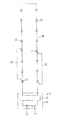
上記安全チョッキは自発光式として、そのチョッキ本体(V)に点在分布する多数の発光ダイオード(LED)(12)と、これらに給電する図10のような電気回路(C)とを備えている。 The safety vest is self-luminous, and includes a large number of light emitting diodes (LEDs) (12) scattered in the vest body (V) and an electric circuit (C) as shown in FIG. Yes.
即ち、図3、4の符号(13)は上記チョッキ本体(V)における左前身頃(1f−L)の前胴面(3)へ、内側(裏側)から縫い付けられた布地などから成るポケットであり、その上部から電源ボックス(14)を収納できるようになっている。そのポケット(13)の上部を開閉するフラップと、これを閉鎖状態に保つ面ファスナーなどの係止具は、図示省略してある。尚、このような電源ボックス(14)を収納するためのポケット(13)は、左前身頃(1f−L)の前胴面(3)に代えて、右前身頃(1f−R)の前胴面(3)や前身頃(1f)の前立て面(2)(2)などへ設置してもさしつかえない。 That is, reference numeral (13) in FIGS. 3 and 4 is a pocket made of cloth sewn from the inner side (back side) to the front waist surface (3) of the left front body (1f-L) in the waistcoat body (V). There is a power box (14) that can be accommodated from above. A flap for opening and closing the upper portion of the pocket (13) and a locking tool such as a hook-and-loop fastener for keeping the pocket closed are not shown. In addition, the pocket (13) for storing such a power supply box (14) replaces the front body surface (3) of the left front body (1f-L), and the front body surface of the right front body (1f-R). It can be installed on the front surface (2) or (2) of (3) or the front body (1f).
上記電源ボックス(14)は開閉蓋付きの硬質な合成樹脂製品であって、これには図11のような電源(15)となる所要数の乾電池(例えば単三形アルカリ乾電池−2本)と回路基板(16)が内蔵されており、外部から押しボタン(電源スイッチ)(17)の操作によってオン・オフできるようになっている。 The power box (14) is a hard synthetic resin product with an open / close lid, which includes a required number of dry batteries (for example, two AA alkaline batteries) serving as a power source (15) as shown in FIG. A circuit board (16) is built in and can be turned on / off by operating a push button (power switch) (17) from the outside.
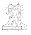
(18)(18)は上記電源(15)と多数の発光ダイオード(LED)(12)とを電気的に接続する2本1組のフレキシブルな被覆電線であり、これは途中での一切カットされておらず、全長に及ぶシームレスな連続一本物として、上記チョッキ本体(V)に付属している電源ボックス(14)からポケット(13)を通じて導出された後、図1の正面図に示す如く、左前身頃(1f−L)の前胴面(3)にある第1反射標識帯(B1)から、その第1反射標識帯(B1)に下端が連結されている第2反射標識帯(左側の第2反射標識帯)(B2)の前立て部(左前立て部)(6)に沿って肩部(左肩部)(7)に到達し、その肩部(左肩部)(7)から引き続き後立て部(左後立て部)(8)に沿って下方へ向かい、その下端に連結されている第1反射標識帯(B1)まで一旦到達する。 (18) and (18) are a set of two flexible covered wires for electrically connecting the power source (15) and a number of light emitting diodes (LEDs) (12). As shown in the front view of FIG. 1, after being led out through the pocket (13) from the power supply box (14) attached to the vest body (V) as a seamless continuous one over the entire length, From the first reflective marker band (B1) on the front trunk surface (3) of the left front body (1f-L), a second reflective marker band (on the left side) is connected to the first reflective marker band (B1). The second reflective marker band (B2) of the front (left front) (6) reaches the shoulder (left shoulder) (7) and continues from the shoulder (left shoulder) (7). Part (left rear standing part) (8) heading downward and connected to its lower end Once reaching a first reflection label band is (B1).
更に、その後立て部(左後立て部)(8)の下端から図2の背面図に示す如く、言わば並び立つ別な第2反射標識帯(右側の第2反射標識帯)(B2)の後立て部(右後立て部)(8)に沿って上方へUターンし、その上端の肩部(右肩部)(7)を経て図1の正面図や図5の側断面図から明白なように、引き続き前立て部(右前立て部)(6)に沿って下方へ向かい、その下端付近の終点まで到達するように長く配線されているのである。 Further, as shown in the rear view of FIG. 2 from the lower end of the rear standing portion (left rear standing portion) (8), so as to stand upside down, another second reflective sign band (right second reflective sign band) (B2) is raised. As shown in FIG. 1 and the side sectional view of FIG. 5, the U-turn is turned upward along the portion (right rear standing portion) (8) and passes through the shoulder (right shoulder) (7) at the upper end. In addition, the wiring is extended long so as to continue downward along the fore part (right erect part) (6) and reach the end point near the lower end.
尚、図1、2、5に基く上記の説明から確認できるように、図示の実施形態では被覆電線(18)(18)を左前身頃(1f−L)にある第2反射標識帯(左側の第2反射標識帯)(B2)の下端付近から配線し始めて、右前身頃(1f−R)にある第2反射標識帯(右側の第2反射標識帯)(B2)の下端付近で終わるようになっているが、被覆電線(18)(18)が左右一対の第2反射標識帯(B2)(B2)における延べ長さの全体に亘るシームレスの連続一本物として配線される限り、その左右何れから配線し始めても良く、配線の進行順序や方向性などは問わない。 In addition, as can be confirmed from the above description based on FIGS. 1, 2, and 5, in the illustrated embodiment, the covered wires (18) and (18) are connected to the second reflective marker band (left side of the left front body (1f-L)). Start wiring near the lower end of the second reflection sign band (B2) and end near the lower end of the second reflection sign band (the right second reflection sign band) (B2) in the right front body (1f-R). However, as long as the covered wires (18) and (18) are wired as a seamless continuous piece over the entire length of the pair of left and right second reflective marker bands (B2) and (B2), Wiring may be started from anywhere, and there is no limitation on the order or direction of the wiring.
そして、上記連続一本物の長い被覆電線(18)(18)が左右一対の第2反射標識帯(B2)(B2)における前立て部(6)(6)と後立て部(8)(8)を通る位置だけに、多数の発光ダイオード(LED)(12)が適当な間隔(D)おきの点在分布状態に取り付けられており、上記電源(15)からの給電を受けるようになっている。 And the said continuous single long covered electric wire (18) (18) is a front part (6) (6) and a rear part (8) (8) in a pair of left and right 2nd reflective sign bands (B2) (B2). A large number of light emitting diodes (LEDs) (12) are attached in a scattered distribution state with an appropriate interval (D) only at a position passing through, and are supplied with power from the power source (15). .
この点、図示の実施形態では発光ダイオード(12)が第2反射標識帯(B2)(B2)における前立て部(6)(6)に左右4個づつ合計8個と、後立て部(8)(8)に同じく左右4個づつ合計8個だけ取り付けられており、その被覆電線(18)(18)上での隣り合う発光ダイオード(12)同士の間隔(D)が約10cmの一定寸法になっている。 In this regard, in the illustrated embodiment, there are a total of eight light emitting diodes (12) on the left and right front parts (6) and (6) in the second reflective marker bands (B2) and (B2), and a rear part (8). Similarly, in the case of (8), a total of 8 left and right 4 pieces are attached, and the distance (D) between adjacent light emitting diodes (12) on the covered wires (18) and (18) is a constant dimension of about 10 cm. It has become.
図12、13はその第2反射標識帯(B2)(B2)に対する各発光ダイオード(12)の取付状態を拡大して示しており、これから明白なように、上記第2反射標識帯(B2)(B2)の前立て部(6)(6)と後立て部(8)(8)には各発光ダイオード(12)のリード線(19)(19)を一緒に受け入れる径大な円形のリード線受け入れ孔(20)と、後述する透明な光拡散カバーの楔脚を受け入れる左右一対の楔脚受け入れ長孔(21)(21)とが開口形成されている。その円形のリード線受け入れ孔(20)は両楔脚受け入れ長孔(21)(21)によって左右方向から挟まれた位置関係にある。 FIGS. 12 and 13 show the mounting state of each light-emitting diode (12) with respect to the second reflective marker strips (B2) and (B2). As will be apparent, the second reflective marker strip (B2) is shown in FIG. The large-diameter circular lead wires for receiving the lead wires (19) and (19) of the respective light-emitting diodes (12) in the front-standing portions (6) and (6) and the rear-standing portions (8) and (8) of (B2). A receiving hole (20) and a pair of left and right wedge leg receiving long holes (21, 21) for receiving a wedge leg of a transparent light diffusion cover described later are formed as openings. The circular lead wire receiving hole (20) is in a positional relationship sandwiched from both the left and right directions by both wedge leg receiving long holes (21) and (21).
又、(22)は上記第2反射標識帯(B2)(B2)の裏面に当てがわれる絶縁座板であって、図14、15に抽出して示す如く、ポリプロピレンなどの硬質な合成樹脂から円形に作成されており、その中央部には上記第2反射標識帯(B2)(B2)側の径大なリード線受け入れ孔(20)と連通する径小な左右一対のリード線受け入れ孔(23)(23)と、その周辺部には同じく第2反射標識帯(B2)(B2)側の上記楔脚受け入れ長孔(21)(21)と合致連通する左右一対の楔脚受け入れ長孔(24)(24)とが、各々開口分布されている。 Further, (22) is an insulating seat plate applied to the back surface of the second reflective marker band (B2) (B2), and is extracted from a hard synthetic resin such as polypropylene as shown in FIGS. A pair of small-diameter left and right lead wire receiving holes (20) communicating with the large lead wire receiving holes (20) on the side of the second reflective marker bands (B2) (B2) are formed in the center portion. 23) (23) and a pair of left and right wedge leg receiving slots which are in communication with the wedge leg receiving slots (21) and (21) on the second reflective marker band (B2) (B2) side in the periphery. (24) and (24) are each aperture-distributed.
そのため、発光ダイオード(12)のリード線(19)(19)を第2反射標識帯(B2)(B2)の表側から、その径大なリード線受け入れ孔(20)と絶縁座板(22)側の径小なリード線受け入れ孔(23)(23)へ差し込むことができ、その差し込んだリード線(19)(19)の先端部と上記被覆電線(18)(18)の保護被膜(25)(25)を剥離した裸線部(26)(26)とが立体交叉する接点を、上記絶縁座板(22)の裏側においてハンダ付けすることにより、通電状態に保つのである。(P)(P)はそのハンダ付け部を示している。 Therefore, the lead wires (19) and (19) of the light emitting diode (12) from the front side of the second reflective marker bands (B2) and (B2), the lead wire receiving hole (20) having a large diameter and the insulating seat plate (22). Can be inserted into the lead wire receiving hole (23) (23) having a smaller diameter on the side, and the leading end of the inserted lead wire (19) (19) and the protective coating (25 ) The contact point where the bare wire portions (26) and (26) from which the (25) has been peeled is three-dimensionally crossed is soldered on the back side of the insulating seat plate (22), thereby maintaining the energized state. (P) (P) indicates the soldered portion.
その場合、図12、13に併せて示す如く、上記リード線(19)(19)と裸線部(26)(26)とのハンダ付け部(P)(P)を、シリコン系接着剤(27)での全体的な被覆状態に固定維持することが好ましい。又、被覆電線(18)(18)は上記電源ボックス(14)の内部においても、シリコン系接着剤(27)によって固定維持することが望ましい。被覆電線(18)(18)がそのハンダ付け部(P)(P)の根元やその他の配線途中から不正に振れ動き変形して、断線するおそれを予防できるからである。 In this case, as shown in FIGS. 12 and 13, the soldered portions (P) and (P) of the lead wires (19) and (19) and the bare wire portions (26) and (26) are replaced with silicon adhesive ( It is preferable to keep the entire covering state in 27) fixed. Further, it is desirable that the covered wires (18) and (18) are fixed and maintained by the silicon-based adhesive (27) even inside the power supply box (14). This is because it is possible to prevent the possibility that the covered electric wires (18) and (18) are swayed and deformed improperly from the roots of the soldered portions (P) and (P) or in the middle of other wirings, and thus disconnected.
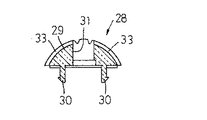
先に一言した光拡散カバー(28)は図16〜18に抽出して示す如く、ポリカーボネートなどの透明な合成樹脂製品であり、絶縁座板(22)とほぼ同じ直径の円錐ヘッド(29)と、これから下向きに突出する左右一対の楔脚(30)(30)とを備え、その楔脚(30)(30)を図12、13のように上記第2反射標識帯(B2)(B2)の表側から、その楔脚受け入れ長孔(21)(21)と絶縁座板(22)側の楔脚受け入れ長孔(24)(24)へ差し込むことによって、発光ダイオード(12)からの発光を広角度(θ)(例えば約120度)に拡散させることができるようになっている。 The light diffusing cover (28) mentioned above is a transparent synthetic resin product such as polycarbonate, as extracted and shown in FIGS. 16 to 18, and has a conical head (29) having substantially the same diameter as the insulating seat plate (22). And a pair of left and right wedge legs (30) and (30) protruding downward from the second leg, and the wedge legs (30) and (30) are connected to the second reflective marker bands (B2) and (B2) as shown in FIGS. ) From the front side of the wedge leg receiving long holes (21) (21) and the wedge leg receiving long holes (24) (24) on the insulating seat plate (22) side, thereby emitting light from the light emitting diode (12). Can be diffused at a wide angle (θ) (for example, about 120 degrees).
光拡散カバー(28)における円錐ヘッド(29)の中央部には上記発光ダイオード(12)の頭部逃し入れ孔(31)が開口形成されており、上記リード線(19)(19)を第2反射標識帯(B2)(B2)から絶縁座板(22)へ差し込み固定した発光ダイオード(12)の頭部(32)は、光拡散カバー(28)の頭部逃し入れ孔(31)内に沈没した包囲状態となるが、上記第2反射標識帯(B2)(B2)の表面から光拡散カバー(28)が一定高さ(H)(例えば約7mm)だけ外方へ背高く膨出するため、これによって大きく拡散される発光ダイオード(12)の発光を、車両運転者がチョッキ着用者の横方向から容易に視認することができ、安全性の確保に役立つ。 A head escape hole (31) of the light emitting diode (12) is formed in the center of the conical head (29) in the light diffusion cover (28), and the lead wires (19) (19) are connected to 2 The head (32) of the light emitting diode (12) inserted and fixed from the reflective sign bands (B2) (B2) to the insulating seat plate (22) is in the head escape hole (31) of the light diffusion cover (28). The light diffusing cover (28) bulges outward from the surface of the second reflective marker strip (B2) (B2) by a certain height (H) (for example, about 7 mm). Therefore, the light emission of the light emitting diode (12) that is greatly diffused by this can be easily seen from the lateral direction of the waistcoat wearer by the vehicle driver, which helps to ensure safety.
更に、上記光拡散カバー(28)における円錐ヘッド(29)の円錐面には多数の排水凹溝(33)が放射対称配列型に付与されており、これに沿って雨水を排出できるようになっているが、その円錐面の光輝性を向上させることにも役立つ。尚、光拡散カバー(28)の楔脚(30)(30)は上記絶縁座板(22)の裏面へ係止し、容易に表側へ抜け出すおそれはない。 Further, a large number of drain grooves (33) are provided on the conical surface of the conical head (29) in the light diffusing cover (28) in a radially symmetric arrangement, and rainwater can be discharged along this. However, it also helps to improve the brightness of the conical surface. Note that the wedge legs (30) and (30) of the light diffusion cover (28) are locked to the back surface of the insulating seat plate (22), and there is no possibility of easily coming out to the front side.
先には発光ダイオード(12)のリード線(19)(19)と、長い被覆電線(18)(18)の裸線部(26)(26)とのハンダ付け部(P)(P)を、シリコン系接着剤(27)での被覆状態に固定することが好ましい旨を説明したが、第2反射標識帯(B2)(B2)の裏面とその第2反射標識帯(B2)(B2)が縫い付けられた前身頃(1f)の就中前立て面(2)(2)や後身頃(1r)の表面との相互間へ、図6、7のように一定帯幅(W6)(例えば約3cm)の粘着性スポンジテープ材(34)を、上記被覆電線(18)(18)とほぼ同じ長さだけ延在する状態に介挿設置して、多数の点在分布状態にあるハンダ付け部(P)(P)の上記シリコン系接着剤(27)を、そのスポンジテープ材(34)により更に裏側からすべて被覆することが望ましい。 First, soldered portions (P) (P) of the lead wires (19) and (19) of the light emitting diode (12) and the bare wire portions (26) and (26) of the long covered wires (18) and (18) are provided. As described above, it is preferable to fix the silicon adhesive (27) in the covering state. However, the back surface of the second reflective marker strip (B2) (B2) and the second reflective marker strip (B2) (B2). A constant band width (W6) (for example, as shown in FIGS. 6 and 7) between the front face (2) (2) of the front body (1f) and the surface of the back body (1r) of the front body (1f) to which The adhesive sponge tape material (34) of about 3 cm) is inserted and installed in a state extending substantially the same length as the above-described covered wires (18) and (18), and soldering in a large number of scattered distribution states The silicone adhesive (27) of the parts (P) and (P) is further backed by the sponge tape material (34). All it is desirable to coat.
そうすれば、そのスポンジテープ材(34)が第2反射標識帯(B2)(B2)に曲げ抵抗を与えることになるため、上記被覆電線(18)(18)の不正な振れ動き変形に起因する断線事故をますます確実に予防することができる。 Then, since the sponge tape material (34) gives a bending resistance to the second reflective marker bands (B2) (B2), it is caused by improper deflection movement deformation of the covered electric wires (18) (18). The disconnection accident can be prevented more reliably.
次に、図19〜22は本考案の好適な変形実施形態を示しており、これではチョッキ本体(V)の前身頃(1f)が後身頃(1r)に比して、荷物の抱え持ち運びによる摺擦や皺寄り変形などを起しやすく、そうすると長い上記被覆電線(18)(18)が左右一対の第2反射標識帯(B2)(B2)における特に前立て部(6)(6)を通る位置で断線するおそれ大となる。 Next, FIGS. 19 to 22 show a preferred modified embodiment of the present invention, in which the front body (1f) of the waistcoat body (V) is more easily carried than the back body (1r). The long covered electric wires (18) and (18) are likely to cause rubbing, wrinkle deformation, and the like, and the long covered wires (18) and (18) particularly pass through the left and right second reflective marker bands (B2) and (B2), in particular, the erect portions (6) and (6). There is a great risk of disconnection at the position.
そのため、2本1組の上記被覆電線(18)(18)が第2反射標識帯(B2)(B2)の前立て部(6)(6)を通る位置だけに、別個な短かい2本1組の第2被覆電線(35)(35)も追加接続することによって、その長い(第1)被覆電線(18)(18)が万一断線事故を起したとしても、全然支障なく通電できる二重回路を形成している。
For this reason, the separate short two
この点、図示実施形態の場合第2反射標識帯(B2)(B2)の前立て部(6)(6)に左右4個づつ点在分布する発光ダイオード(12)のうち、その中間位置の2個づつを言わば間引きした橋絡状態として、最上位置と最下段位置との2個づつを同じ2本1組の短かい第2被覆電線(35)(35)によって各々重畳的に接続している。 In this respect, in the case of the illustrated embodiment, among the light emitting diodes (12) distributed in four on the left and right front portions (6) and (6) of the second reflective marker bands (B2) and (B2), 2 at the intermediate position thereof. In other words, the bridges are thinned out, and the uppermost position and the lowermost position are connected in a superimposed manner by the same pair of short second covered wires (35) (35). .
そして、その第2被覆電線(35)(35)の保護被膜(36)(36)を剥離した裸線部(37)(37)と、上記発光ダイオード(12)のリード線(19)(19)との立体交叉する接点は、やはりハンダ付けされているが、その場合上記連続一本物の長い(第1)被覆電線(18)(18)と別個な短かい第2被覆電線(35)(35)とを上下2段の積み重ね状態として、これらの裸線部(26)(26)(37)(37)に発光ダイオード(12)のリード線(19)(19)を言わば跨がる如く立体交叉させ、そのリード線(19)(19)と上記第1、2被覆電線(18)(18)(35)(35)とを一括にまとめてハンダ付けすることが好ましい。その発光ダイオード(12)のリード線(19)(19)と第1、2被覆電線(18)(18)(35)(35)における裸線部(26)(26)(37)(37)とのハンダ付け部(P)(P)(P)(P)を、1個所(1点)づつに集約する意味である。 And the bare wire part (37) (37) which peeled off the protective film (36) (36) of the 2nd covered electric wire (35) (35), and the lead wire (19) (19) of the said light emitting diode (12) The three-dimensionally crossing contact point is also soldered, but in this case, the continuous second long (first) covered wire (18) (18) and the short second covered wire (35) ( 35) are stacked in two upper and lower stages, and the lead wires (19) and (19) of the light emitting diode (12) are straddled across the bare wire portions (26), (26), (37) and (37). It is preferable that the lead wires (19) and (19) and the first and second covered electric wires (18), (18), (35) and (35) are collectively soldered together. Lead wires (19) and (19) of the light emitting diode (12) and bare wire portions (26), (26), (37) and (37) in the first and second covered electric wires (18), (18), (35) and (35) This means that the soldering parts (P), (P), (P), and (P) are integrated into one place (one point).
尚、図19〜22の変形実施形態においても上記ハンダ付け部(P)(P)(P)(P)をシリコン系接着剤(27)での被覆状態に固定すると共に、その裏側から更に一定帯幅(W6)の長い粘着性スポンジテープ材(34)によって被覆することが好ましいことは、図1〜18の上記実施形態と同じである。その他の構成も図1〜18の上記実施形態と実質的に同じであるため、その図19〜22に図1〜18と同じ符号を記入するにとどめて、その変形実施形態の詳細な説明を省略する。 In addition, in the modified embodiment of FIGS. 19 to 22, the soldered portions (P), (P), (P), and (P) are fixed to the covered state with the silicon-based adhesive (27) and further fixed from the back side. It is the same as that of the said embodiment of FIGS. 1-18 that it is preferable to coat | cover with the adhesive sponge tape material (34) with a long strip | belt width (W6). Other configurations are also substantially the same as those of the above-described embodiment of FIGS. 1 to 18. Therefore, only the same reference numerals as those of FIGS. Omitted.
本考案に係る実施形態の安全チョッキは上記構成を備えており、従来の安全チョッキと同様にして、衣服の外方から上半身に着用されることになる。そして、上記ポケット(13)を開き、電源ボックス(14)の押しボタン(電源スイッチ)(17)をオン操作すれば、点在分布している多数の発光ダイオード(LED)(12)が一挙同時に点滅し、又オフ操作すれば同じく発光ダイオード(12)が消灯する。 The safety waistcoat of the embodiment according to the present invention has the above-described configuration, and is worn on the upper body from the outside of the clothing in the same manner as a conventional safety waistcoat. Then, when the pocket (13) is opened and the push button (power switch) (17) of the power supply box (14) is turned on, a large number of scattered light emitting diodes (LEDs) (12) are simultaneously scattered. When the LED is flashed and turned off, the light emitting diode (12) is turned off.
但し、上記押しボタン(電源スイッチ)(17)を切替スイッチとして、上記発光ダイオード(12)を点滅→連続点灯→消灯の3段式に切替え操作するように構成しても良い。上記発光ダイオード(12)の発光色としても、赤色系の発光ダイオードだけに限らず、その赤色系以外の有彩色発光ダイオードを採用することができる。 However, the push button (power switch) (17) may be used as a changeover switch, and the light emitting diode (12) may be changed over in a three-stage manner of blinking → continuous lighting → off. The light emission color of the light emitting diode (12) is not limited to the red light emitting diode, and a chromatic light emitting diode other than the red light emitting diode can be employed.
何れにしても、上記第2反射標識帯(B2)(B2)の前立て部(6)(6)と後立て部(8)(8)に点在分布している発光ダイオード(12)の点滅又は点灯する発光が、その各個の光拡散カバー(28)(28)によって広角度(θ)に拡散されるため、チョッキ着用者の前後方向からは勿論のこと、横方向(左右方向)からの視認性も高くなり、そのチョッキ着用者の安全性に優れる。 In any case, the flashing of the light emitting diodes (12) scattered in the front portions (6) and (6) and the rear portions (8) and (8) of the second reflective marker bands (B2) and (B2). Or, since the light emission to be lit is diffused at a wide angle (θ) by the individual light diffusion covers (28) and (28), not only from the front and rear direction of the waistcoat wearer, but also from the lateral direction (left and right direction). Visibility is also high, and the waistcoat wearer's safety is excellent.
又、上記発光ダイオード(12)へ給電する被覆電線(18)(18)は、その途中での一切カットされていない全長に亘るシームレスな連続一本物であり、その保護被膜(25)(25)の剥離された裸線部(26)(26)と、これに跨がる如く立体交叉された発光ダイオード(12)のリード線(19)(19)とが、その交叉接点においてハンダ付けされているため、通電状態が著しく安定し、被覆電線(18)(18)の断線するおそれがない。耐用性を著しく向上できるのである。 The covered electric wires (18) and (18) for supplying power to the light emitting diode (12) are seamless and continuous over the entire length that is not cut in the middle, and the protective coatings (25) and (25). The stripped bare wire portions (26) and (26) and the lead wires (19) and (19) of the light emitting diode (12) three-dimensionally crossed over the bare wire portions are soldered at the crossing contacts. Therefore, the energized state is remarkably stable, and there is no possibility that the covered wires (18) and (18) are disconnected. The durability can be remarkably improved.
特に、図19〜22の変形実施形態に説示した構成として、上記被覆電線(18)(18)が第2反射標識帯(B2)(B2)における左右一対の前立て部(6)(6)を通る位置だけに、二重回路となる別個の短かい第2被覆電線(35)(35)を追加接続するならば、万一長い連続一本物の(第1)被覆電線(18)(18)が断線事故を起したとしても、その第2被覆電線(35)(35)によって支障なく発光ダイオード(12)を発光させることができ、耐用性がますます向上する。 In particular, as a configuration illustrated in the modified embodiment of FIGS. 19 to 22, the covered electric wires (18) and (18) are provided with a pair of left and right plackets (6) and (6) in the second reflective marker bands (B 2) and (B 2). If a separate short second covered electric wire (35) (35) that becomes a double circuit is additionally connected only at the position where it passes, the long continuous single (first) covered electric wire (18) (18) Even if a disconnection accident occurs, the second covered wire (35) (35) can cause the light emitting diode (12) to emit light without any trouble, and the durability is further improved.
更に、図1〜18の実施形態と図19〜22の変形実施形態との何れにあっても、被覆電線(18)(18)(35)(35)の裸線部(26)(26)(37)(37)と各発光ダイオード(12)のリード線(19)(19)とのハンダ付け部(P)(P)(P)(P)を、シリコン系接着剤(27)での被覆状態に固定維持するならば、その被覆電線(18)(18)(35)(35)がハンダ付け部(P)(P)(P)(P)の根元から不正に変形するおそれなく、その断線の予防効果がますます向上することになる。 Furthermore, in any of the embodiment of FIGS. 1 to 18 and the modified embodiment of FIGS. 19 to 22, the bare wire portions (26) and (26) of the covered wires (18), (18), (35), and (35). (37) Solder portions (P), (P), (P), and (P) between the lead wires (19) and (19) of the light emitting diodes (12) with the silicon-based adhesive (27). If fixed and maintained in the covered state, the covered electric wires (18), (18), (35), and (35) are not likely to be illegally deformed from the roots of the soldered portions (P) (P) (P) (P), The prevention effect of the disconnection is further improved.
(1f)・前身頃
(1r)・後身頃
(2)・前立て面
(3)・前胴面
(4)(5L)(5R)・面ファスナー
(6)・前立て部
(7)・肩部
(8)・後立て部
(9)・基材シート
(10)・再帰反射性フィルムシート材
(11L)(11R)・サイド縁部
(12)・発光ダイオード
(13)・ポケット
(14)・電源ボックス
(15)・電源
(16)・回路基板
(17)・押しボタン
(18)(35)・被覆電線
(19)・リード線
(20)(23)・リード線受け入れ孔
(21)(24)・楔脚受け入れ長孔
(22)・絶縁座板
(25)(36)・保護被膜
(26)(37)・裸線部
(27)・シリコン系接着剤
(28)・光拡散カバー
(29)・円錐ヘッド
(30)・楔脚
(31)・発光ダイオード逃し入れ孔
(32)・頭部
(33)・排水凹溝
(34)・スポンジテープ材 (C)・電気回路
(B1)・第1反射標識帯
(B2)・第2反射標識帯
(B3)・連結反射標識帯
(P)・ハンダ付け部
(V)・チョッキ本体
(1f) · Front body (1r) · Rear body (2) · Front face (3) · Front torso face (4) (5L) (5R) · Hook fastener (6) · Front part (7) · Shoulder ( 8) ・ Standing part (9) ・ Base sheet (10) ・ Retroreflective film sheet material (11L) (11R) ・ Side edge (12) ・ Light emitting diode (13) ・ Pocket (14) ・ Power supply box (15)-Power supply (16)-Circuit board (17)-Push button (18) (35)-Coated wire (19)-Lead wire (20) (23)-Lead wire receiving hole (21) (24)- Wedge leg receiving long hole (22), insulating seat plate (25) (36), protective coating (26) (37), bare wire part (27), silicon adhesive (28), light diffusion cover (29), Conical head (30), wedge leg (31), light emitting diode escape hole (3 ) ・ Head (33) ・ Drainage ditch (34) ・ Sponge tape material (C) ・ Electric circuit (B1) ・ First reflective marker strip (B2) ・ Second reflective marker strip (B3) ・ Linked reflective marker strip (P) Soldering part (V) Vest body
Claims (5)
その第1反射標識帯に連結された左右一対の前立て部から両肩部を経て、同じく第1反射標識帯に連結された左右一対の後立て部まで連続するほぼV字形の第2反射標識帯と、
その第2反射標識帯に沿って適当な間隔おきに点在分布された多数の発光ダイオードとを備えた自発光式の安全チョッキにおいて、
上記第1反射標識帯又は第2反射標識帯に付属の電源から発光ダイオードへ給電する2本1組の被覆電線が、上記第2反射標識帯における左右何れか一方の前立て部から肩部を経て同じ一方の後立て部の下端に一旦到達し、更にその下端から上方へUターンすることにより、左右何れか他方の後立て部と肩部を経て同じ他方の前立て部の下端付近まで到達することになる長いシームレスの連続一本物として、
その被覆電線の保護被膜を剥離した裸線部と、各発光ダイオードのリード線とが通電状態にハンダ付けされていることを特徴とする自発光式の安全チョッキ。 A first reflective sign strip that can be opened and closed to surround the torso;
A substantially V-shaped second reflection sign band that continues from the pair of left and right front standing parts connected to the first reflection sign band through both shoulders to the pair of left and right rear standing parts similarly connected to the first reflection sign band. When,
In a self-luminous safety waistcoat comprising a number of light emitting diodes scattered at appropriate intervals along the second reflective marker band,
A set of two covered wires for supplying power to the light emitting diodes from the power supply attached to the first reflective marker band or the second reflective marker band passes through the shoulder from the left or right foremost part of the second reflective marker band. Once reaching the lower end of the same one of the rear standing parts, and further making a U-turn upward from the lower end, it reaches the vicinity of the lower end of the same other standing part through the left and right rear raising parts and shoulders. As a long seamless continuous single
A self-luminous safety vest characterized in that the bare wire portion from which the protective coating of the coated electric wire is peeled off and the lead wires of the respective light emitting diodes are soldered in an energized state.
Priority Applications (1)
| Application Number | Priority Date | Filing Date | Title |
|---|---|---|---|
| JP2015004397U JP3200919U (en) | 2015-08-31 | 2015-08-31 | Self-luminous safety waistcoat |
Applications Claiming Priority (1)
| Application Number | Priority Date | Filing Date | Title |
|---|---|---|---|
| JP2015004397U JP3200919U (en) | 2015-08-31 | 2015-08-31 | Self-luminous safety waistcoat |
Publications (1)
| Publication Number | Publication Date |
|---|---|
| JP3200919U true JP3200919U (en) | 2015-11-12 |
Family
ID=54543978
Family Applications (1)
| Application Number | Title | Priority Date | Filing Date |
|---|---|---|---|
| JP2015004397U Expired - Lifetime JP3200919U (en) | 2015-08-31 | 2015-08-31 | Self-luminous safety waistcoat |
Country Status (1)
| Country | Link |
|---|---|
| JP (1) | JP3200919U (en) |
-
2015
- 2015-08-31 JP JP2015004397U patent/JP3200919U/en not_active Expired - Lifetime
Similar Documents
| Publication | Publication Date | Title |
|---|---|---|
| US7735152B2 (en) | EL lighted garment with tear away feature | |
| US7229183B2 (en) | EL lighting for safety orange garments | |
| US6769138B2 (en) | Safety vest and other clothing articles | |
| US20060034064A1 (en) | Illuminated safety vest | |
| US8616719B1 (en) | Lighted safety vest device | |
| US10539312B2 (en) | Enhancing visibility | |
| US20100188843A1 (en) | El power unit | |
| WO2014028442A2 (en) | Illuminated apparel | |
| US20160209016A1 (en) | Activating a Control Module | |
| WO2017222756A1 (en) | Luminous attire | |
| US20080117624A1 (en) | Lighted apparel and footwear | |
| JP3200919U (en) | Self-luminous safety waistcoat | |
| US3083295A (en) | Safety garment | |
| AU2022224808B2 (en) | A Safety Light Apparatus for Headwear | |
| US10939717B2 (en) | Headgear with illuminated decorative piece | |
| GB2477009A (en) | Helmet wrap | |
| US20040114350A1 (en) | Safety vest and other clothing articles | |
| KR200478577Y1 (en) | Safety vest having a light-emitting devece | |
| KR102292927B1 (en) | Smart clothing with luminescent and heating applications | |
| JP3148064U (en) | Safety waistcoat | |
| JP4552127B2 (en) | Safety waistcoat | |
| WO2007047187A2 (en) | Safety lights for connection to people | |
| CN202504397U (en) | Detachable zipper with light strip | |
| KR20090009927U (en) | Safety Vest | |
| JP3236210U (en) | Luminous band for wearing a helmet |
Legal Events
| Date | Code | Title | Description |
|---|---|---|---|
| A521 | Request for written amendment filed |
Free format text: JAPANESE INTERMEDIATE CODE: A821 Effective date: 20150831 |
|
| R150 | Certificate of patent or registration of utility model |
Ref document number: 3200919 Country of ref document: JP Free format text: JAPANESE INTERMEDIATE CODE: R150 |
|
| R250 | Receipt of annual fees |
Free format text: JAPANESE INTERMEDIATE CODE: R250 |
|
| R250 | Receipt of annual fees |
Free format text: JAPANESE INTERMEDIATE CODE: R250 |
|
| R250 | Receipt of annual fees |
Free format text: JAPANESE INTERMEDIATE CODE: R250 |
|
| R250 | Receipt of annual fees |
Free format text: JAPANESE INTERMEDIATE CODE: R250 |
|
| R250 | Receipt of annual fees |
Free format text: JAPANESE INTERMEDIATE CODE: R250 |
|
| R250 | Receipt of annual fees |
Free format text: JAPANESE INTERMEDIATE CODE: R250 |
|
| R250 | Receipt of annual fees |
Free format text: JAPANESE INTERMEDIATE CODE: R250 |
|
| EXPY | Cancellation because of completion of term |