JP3201230U - Seismic fixing - Google Patents
Seismic fixing Download PDFInfo
- Publication number
- JP3201230U JP3201230U JP2015004716U JP2015004716U JP3201230U JP 3201230 U JP3201230 U JP 3201230U JP 2015004716 U JP2015004716 U JP 2015004716U JP 2015004716 U JP2015004716 U JP 2015004716U JP 3201230 U JP3201230 U JP 3201230U
- Authority
- JP
- Japan
- Prior art keywords
- fixture
- notch
- earthquake
- protrusion
- caster
- Prior art date
- Legal status (The legal status is an assumption and is not a legal conclusion. Google has not performed a legal analysis and makes no representation as to the accuracy of the status listed.)
- Expired - Fee Related
Links
- 238000000034 method Methods 0.000 abstract description 7
- 238000005096 rolling process Methods 0.000 description 5
- 238000009434 installation Methods 0.000 description 1
Images





Landscapes
- Legs For Furniture In General (AREA)
- Electrophotography Configuration And Component (AREA)
Abstract
【課題】地震発生時においても、簡便な手法で事務機等の移動や転倒を防止することが可能な耐震用固定具を提供する。【解決手段】耐震用固定具1は、キャスターを床面に固定するために使用されるものであり、板状の固定具本体2の一辺から切り欠いた切欠き3を有し、この切欠き3にキャスターが挿入される。切欠き3は四角形状であり、切欠き3の三辺のそれぞれに沿って、固定具本体2の縁上に設けられた板状の突部4を備えている。固定具本体2の下面には、床上のカーペットに接触する接触部5を備えている。接触部5は、固定具本体2の下面に密着するシートと、シートから突出する突起とから構成されている。突起は、シートから伸びる伸長部と、伸長部の先端からシート側に折り返す折り返し部とから構成されている。【選択図】図1To provide an earthquake-resistant fixture capable of preventing the office machine or the like from moving or falling over by a simple method even when an earthquake occurs. An earthquake-resistant fixture 1 is used for fixing a caster to a floor surface, and has a notch 3 cut out from one side of a plate-like fixture body 2. A caster is inserted into 3. The notch 3 has a quadrangular shape and includes a plate-like protrusion 4 provided on the edge of the fixture main body 2 along each of the three sides of the notch 3. The lower surface of the fixture body 2 is provided with a contact portion 5 that contacts the carpet on the floor. The contact portion 5 includes a sheet that is in close contact with the lower surface of the fixture body 2 and a protrusion that protrudes from the sheet. The protrusion includes an extending portion extending from the sheet, and a folded portion that is folded back from the tip of the extending portion toward the sheet. [Selection] Figure 1
Description
本考案は、オフィスや家屋等に設置された事務機や家具等が、地震の際の揺れによって移動したり倒れたりすることを防止する耐震用固定具に関する。 The present invention relates to an earthquake-resistant fixture that prevents office machines, furniture, and the like installed in offices, houses, and the like from moving or falling due to shaking during an earthquake.
日本においては近年地震が多発しており、地震が発生すると、その揺れによって、オフィスに設置されたコピー機等の事務機や机、家屋に設置された家具等が、本来の設置場所から移動し、倒れることによって、これらの器具が破損するばかりでなく、人への被害の発生の原因となる。東日本大震災の際には、首都圏の高層ビルの高層階において、長周期振動による長時間に亘る横揺れが観測されており、このような横揺れに対応した、オフィス内の機器を床に固定する耐震用固定具が必要とされている。 In Japan, earthquakes have frequently occurred in recent years. When earthquakes occur, office machines such as copy machines installed in offices, desks, furniture installed in houses, etc. move from their original installation locations. By falling, these instruments are not only damaged, but also cause damage to humans. During the Great East Japan Earthquake, rolling over a long period of time due to long-period vibration was observed on the high floors of high-rise buildings in the Tokyo metropolitan area. Equipment in the office that supports such rolling was fixed to the floor. There is a need for seismic fixtures.
キャスター付きの台車や家具を固定することを目的とした固定装置が、特許文献1に記載されている。
オフィスの床面は通常カーペットで覆われており、コピー機等の事務機はこのカーペット上に設置されている。また、事務機の脚部にはキャスターが取り付けられているのが通常である。そのため、カーペット上に設置された状態のキャスター付きの事務機が、地震発生時の横揺れに対しても、移動したり転倒したりすることを防止できる耐震用固定具があれば、器具の破損と人への被害の発生を抑えることができる。 Office floors are usually covered with carpets, and office machines such as copiers are installed on the carpets. Moreover, it is normal that the caster is attached to the leg part of an office machine. Therefore, if there is an earthquake-resistant fixture that can prevent an office machine with a caster installed on a carpet from moving or overturning even if it rolls when an earthquake occurs, the equipment will be damaged. And the occurrence of damage to people can be suppressed.
本考案は、このような事情を考慮してなされたもので、地震発生時においても、簡便な手法で事務機等の移動や転倒を防止することが可能な耐震用固定具を提供することを目的とする。 The present invention has been made in consideration of such circumstances, and is to provide an earthquake-resistant fixture capable of preventing the movement or overturning of an office machine or the like by a simple method even when an earthquake occurs. Objective.
以上の課題を解決するために、本考案の耐震用固定具は、板状の固定具本体の一辺から切り欠いた切欠きを有し、固定具本体の下面には、床上のカーペットに接触する接触部を備え、前記接触部は、前記固定具本体の下面に密着するシートと、前記シートから突出する突起とからなり、前記突起は、シートから伸びる伸長部と、前記伸長部の先端からシート側に折り返す折り返し部とからなることを特徴とする。 In order to solve the above-mentioned problems, the earthquake-resistant fixture of the present invention has a notch cut out from one side of a plate-like fixture body, and the lower surface of the fixture body comes into contact with the carpet on the floor. A contact portion, the contact portion comprising a sheet that is in close contact with the lower surface of the fixture body, and a protrusion that protrudes from the sheet, the protrusion extending from the sheet, and a sheet from the tip of the extension portion It is characterized by comprising a folded portion folded back to the side.
固定具本体に設けられた切欠きにキャスターが挿入されて、キャスターが固定具本体に固定されるともに、固定具本体の下面に設けられた接触部が床上のカーペットに接触することによって、キャスターは床面に固定される。接触部を構成する突起は、シートから伸びる伸長部と、伸長部の先端からシート側に折り返す折り返し部とを備えているため、突起の先端部は湾曲または屈曲した構造となっており、耐震用固定具を床面上のカーペットに設置しただけで、カーペットのループパイルに接触部の突起が引っかかって抜けない状態となる。そのため、地震の長周期振動のように横揺れが生じても、キャスターが移動することを防止でき、事務機等の移動や転倒を防止できる。 The caster is inserted into the notch provided in the fixture main body, the caster is fixed to the fixture main body, and the contact portion provided on the lower surface of the fixture main body comes into contact with the carpet on the floor. Fixed to the floor. The protrusions that make up the contact part have an extension part that extends from the sheet and a folded part that folds back to the sheet side from the tip of the extension part. Just by installing the fixing device on the carpet on the floor, the protrusion of the contact portion is caught on the loop pile of the carpet and cannot be removed. Therefore, even if rolling occurs like the long-period vibration of an earthquake, the caster can be prevented from moving, and the office machine or the like can be prevented from moving or falling.
本考案の耐震用固定具においては、前記切欠きは四角形状であり、前記切欠きの三辺のそれぞれに沿って、前記固定具本体の上面の縁上に設けられた板状の突部を備えている構造とすることが好ましい。 In the seismic fixing tool of the present invention, the notch has a quadrangular shape, and plate-like protrusions provided on the upper edge of the fixing tool body along each of the three sides of the notch. It is preferable that the structure is provided.
切欠きの三辺のそれぞれに沿って、固定具本体の上面の縁上に設けられた板状の突部が、キャスターを三方から支持する構造となるため、キャスターは切欠きの位置に保持され、キャスターが板状の突部を乗り越えて切欠きの位置から移動することを防止できる。 A plate-like protrusion provided on the edge of the upper surface of the fixture body along each of the three sides of the notch has a structure that supports the caster from three directions, so that the caster is held at the notch position. It is possible to prevent the caster from moving over the plate-like protrusion from the position of the notch.
本考案の耐震用固定具においては、前記切欠きは四角形状であり、前記切欠きの一辺に沿って、前記固定具本体の上面の縁上に設けられた板状の突部と、前記板状の突部に連結して設けられて前記切欠きの上部を覆う押え板とを備え、前記押え板はその先端部が開口となった通過孔を備えた構造とすることができる。 In the seismic fixing tool of the present invention, the notch has a rectangular shape, a plate-like protrusion provided on an edge of the upper surface of the fixing tool body along one side of the notch, and the plate And a presser plate that is connected to the projection and covers the upper part of the notch, and the presser plate can have a structure including a passage hole having an opening at the tip.
切欠きの上部を覆う押え板に設けられた通過孔にキャスターの軸を通してキャスターを切欠きの位置に設置すると、切欠きの上部を覆う押え板がキャスターを上部から押える構造となるため、縦方向への揺れが生じても、キャスターは切欠きの位置に保持される。 When the caster is installed at the position of the notch through the caster shaft in the passage hole provided in the presser plate that covers the upper part of the notch, the presser plate that covers the upper part of the notch has a structure that holds the caster from the upper part. The caster is held at the position of the notch even if the swaying occurs.
本考案によると、地震発生時においても、簡便な手法で事務機等の移動や転倒を防止することが可能な耐震用固定具を実現することができる。 According to the present invention, it is possible to realize an earthquake-resistant fixture capable of preventing the office machine or the like from moving or overturning by a simple method even when an earthquake occurs.
以下に、本考案の耐震用固定具を、その実施形態に基づいて説明する。
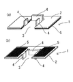
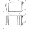
図1に、本考案の第一実施形態に係る耐震用固定具の外観を示す。図1(a)は、耐震用固定具の上面を示しており、図1(b)は、耐震用固定具の下面を示している。
耐震用固定具1は、キャスターを床面に固定するために使用されるものであり、板状の固定具本体2の一辺から切り欠いた切欠き3を有し、この切欠き3にキャスターが挿入される。切欠き3は四角形状であり、切欠き3の三辺のそれぞれに沿って、固定具本体2の上面の縁上に設けられた板状の突部4を備えている。固定具本体2の下面には、床上のカーペットに接触する接触部5を備えている。
Below, the seismic fixing fixture of this invention is demonstrated based on the embodiment.
In FIG. 1, the external appearance of the earthquake-resistant fixture which concerns on 1st embodiment of this invention is shown. Fig.1 (a) has shown the upper surface of the earthquake-resistant fixing tool, and FIG.1 (b) has shown the lower surface of the earthquake-resistant fixing tool.
The earthquake-
図2に、固定具本体2の下面に設けられた接触部5の構造の詳細を示す。図2(a)は、接触部5の部分拡大図である。図2(b)は、カーペット表面の詳細を示し、図2(c)は、カーペット上で接触部5が接触している状態を示す。図2(d)は、図2(c)の部分拡大図である。
In FIG. 2, the detail of the structure of the
図2(a)に示すように、接触部5は、固定具本体2の下面に密着するシート6と、シート6から突出する突起7とから構成されている。突起7は、シート6から伸びる伸長部8と、伸長部8の先端9からシート6側に折り返す折り返し部10とから構成されている。突起7は、シート6の面上に微小なものが多数形成されており、シート6の横方向、縦方向、斜め方向に不規則に配列されている。
As shown in FIG. 2A, the
床上に敷かれたカーペット11は、図2(b)に示すように、その表面にループパイル12が形成されており、耐震用固定具1をカーペット11上に設置すると、図2(c)、図2(d)に示すように、突起7の先端部は湾曲または屈曲した構造となっているため、耐震用固定具1を床面上のカーペット11に設置しただけで、カーペット11のループパイル12に接触部5の突起7が引っかかって抜けない状態となる。そのため、地震の長周期振動のように横揺れが生じても、カーペット11のループパイル12に接触部5の突起7が引っかかった状態が維持され、キャスターの移動が阻止され、事務機等の移動や転倒を防止できる。
As shown in FIG. 2 (b), the
図3に、キャスターを耐震用固定具1に固定した状態を示す。切欠き3の三辺のそれぞれに沿って、固定具本体2の上面の縁上に設けられた板状の突部4が、キャスター13を三方から支持する構造となるため、キャスター13は切欠き3の位置に保持され、キャスター13が板状の突部4を乗り越えて切欠き3の位置から移動することを防止できる。長周期振動による横揺れに伴うキャスター13の乗り越え防止の観点からは、板状の突部4の高さは、20mm程度あれば十分である。
In FIG. 3, the state which fixed the caster to the earthquake-
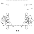
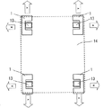
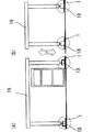
図4に、耐震用固定具1の配置状況を示す。図4においては、事務機14に取付けられている4つのキャスター13のうち、事務機14の前方2か所に取付けられたキャスター13に対して耐震用固定具1を取り付けている。固定具本体2の一辺が開放されているため、切欠き3にキャスター13を挿入しやすい。
In FIG. 4, the arrangement | positioning condition of the earthquake-
図4に示すように、耐震用固定具1の開放側15を内向きにして対向するように配置すると、矢印Xの方向に揺れが生じたときは、固定具本体2の突部4a、4bがキャスター13の移動を阻止し、矢印Yの方向に揺れが生じたときは、固定具本体2の突部4c、4dがキャスター13の移動を阻止する。
As shown in FIG. 4, when the
このように、耐震用固定具1の開放側15を内向きにして対向するように配置することにより、矢印で示すどの方向に揺れが生じても、キャスター13は切欠き3の位置に保持される。
In this way, by disposing the
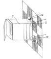
図5は、事務機14の前方2か所に取付けられたキャスター13に対して耐震用固定具1を取り付けた状態の斜視図である。図6(a)は、同様の取付け状態の正面図であり、図6(b)は、その側面図である。図7は、取付け状態の底面を示す図である。
耐震用固定具1をこのように取り付けることによって、地震発生時においても、簡便な手法で事務機等の移動や転倒を防止することができる。
FIG. 5 is a perspective view of the state in which the earthquake-
By attaching the earthquake-
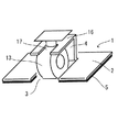
図8に、本考案の第二実施形態に係る耐震用固定具の外観を示す。図8(a)は、耐震用固定具の上面を示しており、図8(b)は、耐震用固定具の下面を示している。
耐震用固定具1は、キャスターを床面に固定するために使用されるものであり、板状の固定具本体2の一辺から切り欠いた切欠き3を有し、この切欠き3にキャスターが挿入される。切欠き3は四角形状であり、切欠き3の一辺に沿って、固定具本体2の上面の縁上に設けられた板状の突部4と、板状の突部4に連結して設けられて切欠き3の上部を覆う押え板16とを備えている。押え板16はその先端部が開口となった通過孔17を備えている。固定具本体2の下面には、床上のカーペットに接触する接触部5を備えている。接触部5の構造と機能は、第一実施形態と同様である。
In FIG. 8, the external appearance of the earthquake-resistant fixture which concerns on 2nd embodiment of this invention is shown. FIG. 8A shows the upper surface of the earthquake-resistant fixture, and FIG. 8B shows the lower surface of the earthquake-resistant fixture.
The earthquake-
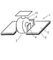
図9に、キャスターを耐震用固定具1に固定した状態を示す。
切欠き3の上部を覆う押え板16に設けられた通過孔17にキャスター13の軸を通してキャスター13を切欠き3の位置に設置すると、切欠き3の上部を覆う押え板16がキャスター13を上部から押える構造となっているため、縦方向への揺れが生じても、キャスター13は切欠き3の位置に保持される。固定具本体2の一辺が開放されており、通過孔17は押え板16の先端部が開口となるように形成されて、固定具本体2の開放側と押え板16の開口部の方向が一致しているため、切欠き3にキャスター13を挿入しやすい。
In FIG. 9, the state which fixed the caster to the earthquake-
When the
図10に、耐震用固定具1の配置状況を示す。図10においては、事務機14に取付けられている4つのキャスター13全てに対して耐震用固定具1を取り付けている。図10に示すように耐震用固定具1を配置すると、矢印Xの方向、矢印Yの方向のいずれに揺れが生じても、キャスター13の移動が阻止される。
In FIG. 10, the arrangement | positioning condition of the earthquake-
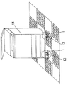
図11は、事務機14の4か所に取付けられたキャスター13に対して耐震用固定具1を取り付けた状態の斜視図である。図12(a)は、同様の取付け状態の正面図であり、図12(b)は、その側面図である。耐震用固定具1をこのように取り付けることによって、図12に示す矢印Zの方向の揺れが生じても、簡便な手法で事務機等の移動や転倒を防止することができる。
FIG. 11 is a perspective view of a state in which the earthquake-
図13に、机の脚部を耐震用固定具1に固定した状態を示す。
切欠き3の上部を覆う押え板16に設けられた通過孔17に脚部18の軸を通して脚部18を切欠き3の位置に設置すると、切欠き3の上部を覆う押え板16が脚部18を上部から押える構造となるため、縦方向への揺れが生じても、脚部18は切欠き3の位置に保持される。固定具本体2の一辺が開放されており、通過孔17は押え板16の先端部が開口となるように形成されて、固定具本体2の開放側と押え板16の開口部の方向が一致しているため、切欠き3に脚部18を挿入しやすい。
In FIG. 13, the state which fixed the leg part of the desk to the earthquake-
When the
図14に、耐震用固定具1の配置状況を示す。図14においては、机19に取付けられている4つの脚部18全てに対して耐震用固定具1を取り付けている。図14に示すように耐震用固定具1を配置すると、矢印Xの方向、矢印Yの方向のいずれに揺れが生じても、脚部18の移動が阻止される。
In FIG. 14, the arrangement | positioning condition of the earthquake-
図15は、机19の4か所に取付けられた脚部18に対して耐震用固定具1を取り付けた状態の斜視図である。図16(a)は、同様の取付け状態の正面図であり、図16(b)は、その側面図である。耐震用固定具1をこのように取り付けることによって、図16に示す矢印Zの方向の揺れが生じても、簡便な手法で机等の移動や転倒を防止することができる。
FIG. 15 is a perspective view of a state in which the earthquake-
本考案は、地震発生時においても、簡便な手法で事務機等の移動や転倒を防止することが可能な耐震用固定具として広く利用することができる。 INDUSTRIAL APPLICABILITY The present invention can be widely used as an earthquake-resistant fixture capable of preventing the movement or overturning of an office machine or the like by a simple method even when an earthquake occurs.
1 耐震用固定具
2 固定具本体
3 切欠き
4、4a、4b、4c、4d 板状の突部
5 接触部
6 シート
7 突起
8 伸長部
9 先端
10 折り返し部
11 カーペット
12 ループパイル
13 キャスター
14 事務機
15 開放側
16 押え板
17 通過孔
18 脚部
19 机
DESCRIPTION OF
Claims (3)
Priority Applications (1)
| Application Number | Priority Date | Filing Date | Title |
|---|---|---|---|
| JP2015004716U JP3201230U (en) | 2015-09-16 | 2015-09-16 | Seismic fixing |
Applications Claiming Priority (1)
| Application Number | Priority Date | Filing Date | Title |
|---|---|---|---|
| JP2015004716U JP3201230U (en) | 2015-09-16 | 2015-09-16 | Seismic fixing |
Publications (1)
| Publication Number | Publication Date |
|---|---|
| JP3201230U true JP3201230U (en) | 2015-11-26 |
Family
ID=54610882
Family Applications (1)
| Application Number | Title | Priority Date | Filing Date |
|---|---|---|---|
| JP2015004716U Expired - Fee Related JP3201230U (en) | 2015-09-16 | 2015-09-16 | Seismic fixing |
Country Status (1)
| Country | Link |
|---|---|
| JP (1) | JP3201230U (en) |
Cited By (2)
| Publication number | Priority date | Publication date | Assignee | Title |
|---|---|---|---|---|
| JP2023006824A (en) * | 2021-06-30 | 2023-01-18 | 株式会社タツフト | Movement-suppression silicon mat for cooking appliance and set of the movement-suppression silicon mats |
| JP7566487B2 (en) | 2020-05-11 | 2024-10-15 | キヤノン株式会社 | Anti-tip device, sheet feeding device and image forming apparatus |
-
2015
- 2015-09-16 JP JP2015004716U patent/JP3201230U/en not_active Expired - Fee Related
Cited By (2)
| Publication number | Priority date | Publication date | Assignee | Title |
|---|---|---|---|---|
| JP7566487B2 (en) | 2020-05-11 | 2024-10-15 | キヤノン株式会社 | Anti-tip device, sheet feeding device and image forming apparatus |
| JP2023006824A (en) * | 2021-06-30 | 2023-01-18 | 株式会社タツフト | Movement-suppression silicon mat for cooking appliance and set of the movement-suppression silicon mats |
Similar Documents
| Publication | Publication Date | Title |
|---|---|---|
| JP4679926B2 (en) | Fall prevention tool for floor-standing pipe support | |
| JP2016214612A (en) | Furniture with a top plate | |
| JP2009249820A (en) | Joint device for boundary | |
| JP5279798B2 (en) | Base-isolated floor structure | |
| JP5969280B2 (en) | Door shaft retaining structure and door | |
| JP6877279B2 (en) | Interlayer refractory support metal fittings and interlayer refractory support method | |
| JP2005207703A (en) | Mounting structure of air conditioner outdoor unit in base-isolated building | |
| JP2006169773A (en) | Base isolation device for wooden house | |
| KR20070000458U (en) | Removable mop tray | |
| JP2020100975A (en) | Ceiling material retainer clip | |
| JP5349749B2 (en) | Furniture fall prevention fixture | |
| JP2013014907A (en) | Floor panel positioning cap | |
| JP2018003371A (en) | Base-isolated floor structure and cushioning material | |
| KR102065846B1 (en) | Electic cable tray for seismic reinforcing of access floor | |
| JP3138307B2 (en) | Seismic isolation floor members | |
| KR20190001512U (en) | cross binding device for furniture support pipes | |
| JP2025110843A (en) | Furniture fall prevention device | |
| JP3819697B2 (en) | Floor support shock absorber | |
| JP2014062417A (en) | Frame for bay window, house with the frame for bay window, and show house exhibition facility | |
| JP2009249815A (en) | Movable partition wall and installation structure of movable partition wall | |
| JP3113437U (en) | Earthquake resistant storage furniture | |
| JP5502063B2 (en) | Furniture fall prevention fixture | |
| JP6576314B2 (en) | Tatami anti-slip device | |
| JPS6111388Y2 (en) | ||
| JP3193975U (en) | Drawer divider |
Legal Events
| Date | Code | Title | Description |
|---|---|---|---|
| R150 | Certificate of patent or registration of utility model |
Ref document number: 3201230 Country of ref document: JP Free format text: JAPANESE INTERMEDIATE CODE: R150 |
|
| LAPS | Cancellation because of no payment of annual fees |