JP3201493U - Agricultural carrier - Google Patents
Agricultural carrier Download PDFInfo
- Publication number
- JP3201493U JP3201493U JP2015004935U JP2015004935U JP3201493U JP 3201493 U JP3201493 U JP 3201493U JP 2015004935 U JP2015004935 U JP 2015004935U JP 2015004935 U JP2015004935 U JP 2015004935U JP 3201493 U JP3201493 U JP 3201493U
- Authority
- JP
- Japan
- Prior art keywords
- frame
- pair
- frames
- carrier
- load
- Prior art date
- Legal status (The legal status is an assumption and is not a legal conclusion. Google has not performed a legal analysis and makes no representation as to the accuracy of the status listed.)
- Expired - Fee Related
Links
Images


Landscapes
- Handcart (AREA)
- Agricultural Machines (AREA)
Abstract
【課題】丈の低い積荷でも容易に荷台枠に荷上げ、荷降ろしでき、不使用時には極く簡単な操作でコンパクトに折り畳める農作業用キャリアを提供する。【解決手段】平面視が矩形状で前枠3、後枠4、および左右一対の側枠5を含む荷台枠2と、後枠4の中間の後方Rに配設した左右一対の後輪Wと、荷台枠2の前枠3、後枠4、側枠5ごとにおける水平方向の中間から立設した前後左右4つの荷支え枠8,9,10と、前枠3の前方に配置した方向自在な前輪wと、荷台枠2の前枠3の斜め前方Fに配置された丁番金具16と、丁番金具16の一方17に基端側を回転可能に取り付けられ、先端に位置する握り枠24により連結された左右一対の牽引枠23と、を備え、一対の牽引枠23は、それらの基端側を回転中心として後方Rに回転させた際に、荷台枠2の後枠4に接して支持され、前枠3および後枠4の荷支え枠8,9を一対の牽引枠23の間から立設させる。【選択図】図1[PROBLEMS] To provide a carrier for agricultural work that can be easily loaded and unloaded on a carrier frame even with a low load, and can be folded compactly by a very simple operation when not in use. A load carrier frame 2 having a rectangular shape in a plan view and including a front frame 3, a rear frame 4, and a pair of left and right side frames 5, and a pair of left and right rear wheels W disposed at a rear R in the middle of the rear frame 4. And four front and rear left and right load support frames 8, 9, 10, which are erected from the middle in the horizontal direction for each of the front frame 3, the rear frame 4, and the side frame 5 of the loading platform frame 2, and the direction of the front frame 3. A free front wheel w, a hinge bracket 16 disposed diagonally forward F of the front frame 3 of the cargo carrier frame 2, and a gripping member mounted on one end 17 of the hinge bracket 16 so that its proximal end is rotatable and located at the distal end. A pair of left and right traction frames 23 connected by a frame 24, and the pair of traction frames 23 are attached to the rear frame 4 of the loading platform frame 2 when they are rotated rearward R with their base end sides as rotation centers. The load supporting frames 8 and 9 of the front frame 3 and the rear frame 4 are erected from between the pair of traction frames 23. [Selection] Figure 1
Description
本考案は、例えば、消毒、施肥、除草、収穫のような各種の農作業に用いられ、狭い畝の間などにおいても安定した姿勢で容易移動できると共に、不使用時には極く簡単な操作によりコンパクトに折り畳める農作業用キャリアに関する。 The present invention is used for various farming operations such as disinfection, fertilization, weeding, and harvesting, and can be easily moved in a stable posture even in a narrow fence, etc. The present invention relates to a folding farm carrier.
本考案者は、先に、種々の農作業に用いられ、各種サイズの薬液タンクや収納容器などを自在に積載できると共に、不使用時にはコンパクトに折り畳める農作業用運搬車を提案している(例えば、特許文献1参照)。
更に、本考案者は、例えば、田畑で隣接する畝同士間などの狭い路地であっても、畝や作物などを傷付けることなく、安定した姿勢で容易に移動ししつ、施肥、除草、あるいは収穫などの農作業が行えると共に、不使用時には全体を薄く且つコンパクトに折り畳める農作業用キャリアも提案している(例えば、特許文献2参照)。
The present inventor has previously proposed an agricultural transport vehicle that can be used for various farm work and can be loaded with various sizes of chemical tanks and storage containers and can be folded compactly when not in use (for example, patents). Reference 1).
Furthermore, the present inventor, for example, even in a narrow alley between adjacent ridges in a field, for example, fertilization, weeding, or A farm work carrier that can perform farm work such as harvesting and can be folded thinly and compactly when not in use has also been proposed (see, for example, Patent Document 2).
しかし、前記農作業用運搬車や農作業用キャリアでは、薬液タンクや収納容器などの底面を支持する荷台枠と、その上方における一定の高さに配置され且つ平面視の外形が相似形である荷囲い枠と、を複数本の旋回枠などを介して連結することで、やや縦長の積荷スペースを形成している。そのため、丈の低い収穫用容器などの積荷の場合、係る積荷を載せたり、取り出す際に、上方の荷囲い枠や複数の旋回枠などが却って上記作業の支障になる場合があった。しかも、上記荷囲い枠を一定の高さに保つため、該荷囲い枠の前枠と、斜め前方に延びた左右一対の牽引枠との間に、両者を位置決めするための脱着式の係止枠を装着しているので、構造が複雑化し、且つ構成部材の数も多くならざるを得ない、という問題もあった。 However, in the agricultural transport vehicle and the agricultural carrier, the loading frame that supports the bottom surface of the chemical solution tank, the storage container, and the like, and the load enclosure that is arranged at a certain height above and has a similar external shape in plan view. By connecting the frame to each other via a plurality of revolving frames or the like, a slightly vertically long cargo space is formed. For this reason, in the case of a load such as a harvesting container having a low height, when the load is placed or taken out, the upper frame or the plurality of swivel frames may be obstructed and the above work may be hindered. Moreover, in order to maintain the load enclosure frame at a certain height, a detachable latch for positioning the load enclosure frame between the front frame of the load enclosure frame and a pair of left and right traction frames extending obliquely forward. Since the frame is mounted, there is a problem that the structure is complicated and the number of components must be increased.
本考案は、背景技術で説明した問題点を解決し、丈の低い収穫用容器などの積荷であっても容易に荷台枠に荷上げしたり、荷降ろしでき、不使用時には極く簡単且つ迅速な操作でコンパクトに折り畳めると共に、簡素な構造で且つ構成部材数を少なくした農作業用キャリアを提供する、ことを課題とする。 The present invention solves the problems described in the background art, and even a load such as a low harvesting container can be easily loaded and unloaded on the carrier frame, and it is extremely simple and quick when not in use. It is an object of the present invention to provide a carrier for farm work that can be folded compactly with a simple operation and has a simple structure and a reduced number of components.
本考案は、前記課題を解決するため、積荷の底面側を支持する荷台枠を構成する前枠、後枠、および左右一対の側枠の中間にそれぞれ荷支え枠を個別に立設し、使用時に上記前枠から斜め前方に延びた左右一対の牽引枠を丁番金具によって上記荷台枠上に折り畳め、且つこの際に上記左右一対の牽引枠の間から上記前枠および後枠に設けた各荷支え枠が立設する、ことに着想して成されたものである。 In order to solve the above problems, the present invention separately uses a load support frame that stands between the front frame, the rear frame, and the pair of left and right side frames that constitute the load frame that supports the bottom side of the load. Sometimes a pair of left and right traction frames extending obliquely forward from the front frame is folded on the cargo bed frame by hinges, and at this time, each of the front and rear frames provided between the pair of left and right traction frames It was created with the idea that a cargo support frame would be erected.
即ち、本考案による第1の農作業用キャリア(請求項1)は、平面視の外形が矩形状で且つ前枠、後枠、および左右一対の側枠を含む荷台枠と、前記後枠における水平方向の中間から後方に延びた支持枠に軸支される左右一対の後輪と、上記荷台枠の前枠、後枠、および左右一対の側枠ごとにおける水平方向の中間から立設した前後左右4つの荷支え枠と、上記前枠の前方に水平状に張り出した台座の底面に取り付けられた1つまたは2つの方向自在な前輪と、上記荷台枠の前枠から斜め前方に延びた一対の支持枠の前端側に固定された丁番金具と、上記丁番金具の一方に基端側を回転可能に取り付けられ、且つ先端に位置する水平な握り枠によって連結された左右一対の牽引枠と、を備えた農作業用キャリアであって、上記握り枠を含む左右一対の牽引枠は、上記荷台枠側から離れ且つ斜め前方に延びた牽引時から、それらの基端側を回転中心として後方に回転させた際に、上記荷台枠の後枠に接して支持されると共に、上記前枠および後枠ごとの上記前後一対の荷支え枠を当該一対の牽引枠の間から立設させる、ことを特徴とする。 That is, the first agricultural carrier according to the present invention (Claim 1) has a rectangular shape in plan view and includes a front frame, a rear frame, and a pair of left and right side frames, and a horizontal frame in the rear frame. A pair of left and right rear wheels pivotally supported by a support frame extending rearward from the middle in the direction, and front, rear, left and right standing from the middle in the horizontal direction for each of the front frame, the rear frame, and the pair of left and right side frames. Four load-supporting frames, one or two directional front wheels attached to the bottom surface of the pedestal horizontally projecting in front of the front frame, and a pair of diagonally extending forwards from the front frame of the load-bearing frame A hinge bracket fixed to the front end side of the support frame, and a pair of left and right traction frames attached to one of the hinge brackets so that the base end side is rotatable and connected by a horizontal gripping frame located at the distal end. , A carrier for farm work, including the grip frame on the left The pair of traction frames are supported in contact with the rear frame of the load carrier frame when towed away from the load carrier frame side and obliquely extending forward and then rotated rearward with the base end side as a rotation center. And the pair of front and rear load support frames for each of the front frame and the rear frame is erected from between the pair of traction frames.
また、本考案による第2の農作業用キャリア(請求項2)は、平面視の外形が矩形状で且つ前枠、後枠、および左右一対の側枠を含む荷台枠と、前記左右一対の側枠ごとの外側に軸支された左右一対の後輪と、上記荷台枠の前枠および後枠における水平方向の中間から立設した前後一対の荷支え枠、および上記左右一対の後輪の車輪カバーごとの上面から立設した左右一対の荷支え枠と、上記前枠の前方に水平状に張り出した台座の底面に取り付けられた1つまたは2つの方向自在な前輪と、上記荷台枠の前枠から斜め前方に延びた一対の支持枠の前端側に固定された丁番金具と、上記丁番金具の一方に基端側を回転可能に取り付けられ、且つ先端に位置する水平な握り枠によって連結された左右一対の牽引枠と、を備えた農作業用キャリアであって、上記左右一対の牽引枠は、上記荷台枠側から離れ且つ斜め前方に延びた牽引時から、それらの基端側を回転中心として後方に回転させた際に、上記荷台枠の後枠に接して支持されると共に、該荷台枠の前枠および後枠ごとの上記前後一対の荷支え枠を当該一対の牽引枠の間から立設させる、ことを特徴とする。 In addition, a second carrier for farm work according to the present invention (Claim 2) has a rectangular outer shape in plan view and includes a front frame, a rear frame, and a pair of left and right side frames, and the pair of left and right sides. A pair of left and right rear wheels pivotally supported on the outside of each frame; a pair of front and rear load support frames erected from the horizontal middle of the front frame and the rear frame of the load carrier frame; and the wheels of the pair of left and right rear wheels A pair of left and right load support frames erected from the upper surface of each cover, one or two directional front wheels attached to the bottom surface of the pedestal horizontally projecting in front of the front frame, and the front of the load carrier frame A hinge bracket fixed to the front end side of a pair of support frames that extend diagonally forward from the frame, and a horizontal gripping frame that is rotatably attached to one of the hinge brackets and has a proximal end side positioned at the distal end A farm carrier comprising a pair of coupled left and right tow frames The pair of left and right tow frames are separated from the cargo bed frame side and extended obliquely forward from the rear frame of the cargo bed frame when rotated backward with the base end side as a rotation center. The pair of front and rear load support frames for each of the front frame and the rear frame of the load carrier frame are erected from between the pair of traction frames.
前記第1の農作業用キャリアおよび第2の農作業用キャリアによれば、以下の効果(1)〜(3)を奏することが可能となる。
(1)前記第1の農作業用キャリアでは、前記荷台枠の四辺の各枠から、また、前記第2の農作業用キャリアでは、上記荷台枠の前後枠の中間と、前記左右一対の後輪の車輪カバーごととの上面から前後左右4つの荷支え枠を立設しているので、何れ農作業用キャリアのも、積荷の丈に拘わらず、各種の積荷を容易に積み込み、運搬し、降ろすことができる。
(2)不使用時には、前記左右一対の牽引枠を、斜め前方に延びた牽引時から、それらの基端側(前記丁番金具側)を回転中心として後方に回転させることで、荷台枠の後枠に接して支持でき、この際に前後一対の荷支え枠とは干渉しないと共に、上記左右一対の牽引枠の間に、前後一対の荷支え枠を立設させることができる。従って、極く簡単な操作で迅速に折り畳んで、コンパクトに収納できる。
(3)農作業用キャリア全体の構造および機構の簡素であり、且つ構成部材数が少なくなるので、低コスト化で製作することが可能となる。
According to the first farmwork carrier and the second farmwork carrier, the following effects (1) to (3) can be achieved.
(1) In the first farm work carrier, from each of the four sides of the load carrier frame, and in the second farm work carrier, between the front and rear frames of the load carrier frame and the pair of left and right rear wheels. Since four load support frames are erected from the upper surface of each wheel cover, front, rear, left and right, any carrier can easily load, transport and drop various loads regardless of the length of the load. it can.
(2) When not in use, the pair of left and right traction frames are rotated rearward around their base end side (the hinge bracket side) from the time of traction extending diagonally forward, thereby The pair of front and rear load support frames can be erected between the pair of left and right traction frames, and can be supported in contact with the rear frame. Therefore, it can be folded quickly and stored compactly with an extremely simple operation.
(3) Since the structure and mechanism of the entire carrier for farm work is simple and the number of constituent members is reduced, it can be manufactured at a low cost.
尚、前記荷台枠、荷支え枠、牽引枠、および、握り枠は、例えば、直径数cmのステンレス鋼管やアルミニウム管などを曲げ加工や溶接したものが用いられる。
また、第1および第2の農作業用キャリアの前記荷台枠は、平面視において、互いに同様のサイズであるか、互いに相似形の矩形(正方形または長方形)状を呈する。
更に、前記一対の後輪は、一対の2重車輪(ダブルタイヤ)を隣接してなる形態であっても良い。
加えて、前記丁番金具は、丁番により連結された一対の回転金具と固定金具とからなり、前者の金具に前記左右一対の牽引枠の基端側が固定され、後者の金具に前記荷台枠の前枠から斜め前方に延びた一対の支持枠の前端側に固定される。
For example, the load frame, the load support frame, the pulling frame, and the grip frame may be formed by bending or welding a stainless steel tube or an aluminum tube having a diameter of several centimeters.
In addition, the carrier frames of the first and second agricultural carriers have the same size as each other in plan view, or have a similar rectangular shape (square or rectangular shape).
Further, the pair of rear wheels may have a pair of double wheels (double tires) adjacent to each other.
In addition, the hinge metal fitting is composed of a pair of rotating metal fittings and fixed metal fittings connected by hinges, and the base end sides of the pair of left and right pulling frames are fixed to the former metal fitting, and the load carrier frame is attached to the latter metal fitting. The front frame is fixed to the front end side of a pair of support frames that extend obliquely forward from the front frame.
更に、本考案には、前記4つの荷支え枠は、側面視で外側にく字状あるいは円弧形状に突出する形状を呈する、農作業用キャリア(請求項3)も含まれる。
これによれば、例えば、丈の高い薬液タンクなどの積荷であっても、その各側面あるいは周面に上記4つの荷支え枠ごとの上辺枠が、常に接触するので、これらの側面などを痛めずに水平方向の移動を阻止して運搬できると共に、丈の低い積荷であっても確実に運搬することができる(効果(4))。
Furthermore, the present invention includes an agricultural carrier (Claim 3) in which the four load-supporting frames have a shape that protrudes outward or in an arc shape when viewed from the side.
According to this, for example, even in the case of a load such as a high chemical tank, the upper side frame for each of the four load support frames always comes into contact with each side surface or the peripheral surface thereof. In addition, it can be transported while preventing horizontal movement, and can be transported reliably even with a low-load (effect (4)).
加えて、本考案には、前記方向自在な前輪が1つであり、かかる前輪の両側には、斜め下側および外側に拡がる左右一対の補助輪が前記台座を介して取り付けられている、農作業用キャリア(請求項4)も含まれる。
これによれば、1つの方向自在な前輪と左右一対の後輪とからなる三輪車の形態となるが、前輪の左右に斜め下側および外側に拡がる左右一対の補助輪が取り付けられているので、凹凸のある畝間の路地や、田畑などで牽引しても左右に倒れにくくして搬送することができる(効果(5))。特に、一対の後輪間の間隔が比較的狭い前記第1の農作業用キャリアの場合には、有効である。
In addition, in the present invention, there is one directional front wheel, and a pair of left and right auxiliary wheels extending obliquely downward and outward are attached to both sides of the front wheel via the pedestal. Carriers (claim 4) are also included.
According to this, although it becomes a form of a tricycle consisting of one unidirectional front wheel and a pair of left and right rear wheels, a pair of left and right auxiliary wheels extending obliquely downward and outward are attached to the left and right of the front wheel, Even if it is towed in an alley with uneven ridges or in a field, it can be transported without falling to the left or right (effect (5)). This is particularly effective in the case of the first farmwork carrier in which the distance between the pair of rear wheels is relatively narrow.
以下において、本考案を実施するための形態について説明する。
図1(A)は、本考案による第1の農作業用キャリア1aを示す斜視図である。尚、以下における図中の符号Fは、本キャリア1a,1bの前方を示し、符号Rは、本キャリア1a,1bの後方を示す。
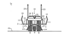
係る農作業用キャリア1aは、図1(A)に示すように、平面視の外形が矩形(長方形または正方形)状で且つ前枠3、後枠4、および左右一対の側枠5を含む荷台枠2と、前記前枠3、後枠4、一対の側枠5ごとの中間から個別に立設した荷支え枠8,9,10,10と、上記荷台枠2の後枠5の中間から後方に延びた位置に配設された左右一対の後輪Wと、上記荷台枠2の前枠3の中央付近の前方に配置された転動方向が自在な1つの前輪(方向自在輪)wと、を備えている。
Below, the form for implementing this invention is demonstrated.
FIG. 1A is a perspective view showing a first farmwork carrier 1a according to the present invention. In addition, the code | symbol F in the figure below shows the front of this
As shown in FIG. 1A, the agricultural carrier 1a has a rectangular shape (rectangular or square) in plan view, and includes a
尚、前記荷台枠2は、例えば、平面視で一辺が約30cmの正方形状、または、前後(F−R)方向の長さが約20cmで且つ幅が約31cmの長方形状である。
前記荷台枠2の内側で且つやや低い位置には、前後(F−R)方向に沿った1本の荷支持枠6と、左右一対(2本)の荷支持枠7とが前枠3と後枠5との中間で水平に配置されている。尚、該荷支持枠6,7は、4本以上としたり、平面視で縦横に交叉する格子形状を呈する形態としても良い。
上記荷支持枠6の両端は、後述する縦板13と台座26とに接続されている。また、上記2本の荷支持枠7の両端は、何れも前枠3または後枠4に溶着されたアール片12を介して、前記前枠3または後枠5に支持されている。
The
Inside the
Both ends of the
図1(A)、図2〜図3に示すように、上記アール片12の上端ごとには、側面視で荷台枠2の外側に「く」字状にやや突出した縦片11が連続して立設し、幅方向で隣接する一対の縦片11の上端間には、前述した荷支え枠8,9が接続されている。該荷支え枠8,9は、何れも上記一対の縦片11を含んでいる。また、前記左右一対の側枠5の中間にも前後一対の縦片11を含む荷支え枠10が立設されている。更に、荷支え枠8,9,10の上片は、何れも前記前枠3、後枠4、および側枠5の何れかと平面視で重複している。
尚、上記縦片11は、側面視で荷台枠2の外側に円弧形状に突出した形態であっても良い。また、図2中の符号GLは、田畑や畝間などにおける路地の地面を示している。
As shown in FIG. 1 (A) and FIGS. 2 to 3, for each upper end of the
In addition, the form which protruded in the circular arc shape may be sufficient as the said
図1(A)〜図3に示すように、前記荷台枠2の前枠3における中間から前方F側に水平状に台座(板)26が突設して溶着され、該台座26の底面における中央部には、前記前輪wが軸支金具28を介して方向自在に取り付けられている。
尚、前記一対の後輪Wおよび上記前輪wは、何れも、空気タイヤ、あるいは、合成ゴムまたは合成樹脂からなり、且つ所要の柔軟性を有する中実のノーパンクタイヤである。尚、前輪wは、左右一対(2つ)としても良い。
前記左右一対の後輪Wは、直径が約21cmであり、図1(A),図3に示すように、前記荷台枠2の後枠5の中央部に溶着された垂直な縦板13と、該縦板13の後方R側に接合された平面視がコ字形の支持枠14とを介して、該支持枠14における一対の側片の外側ごとに対称に軸支されている。
As shown in FIGS. 1 (A) to 3, a pedestal (plate) 26 protrudes and is welded horizontally from the middle of the
Note that each of the pair of rear wheels W and the front wheel w is a pneumatic tire, or a solid no-puncture tire made of synthetic rubber or synthetic resin and having the required flexibility. The front wheels w may be a pair of left and right (two).
The pair of left and right rear wheels W have a diameter of about 21 cm, and as shown in FIGS. 1A and 3, a vertical
また、前記台座26の底面には、前記前輪wよりも若干前方F側の位置において、左および右の斜め下側に対称に延びた一対の支持金具27が固定され、係る支持金具27ごとの下端の外側面には、正面視でハ字形状の左右対称で且つ斜め下側に向かう一対の補助車輪awが軸支されている。係る補助車輪awは、硬質樹脂あるいは硬質ゴムからなる。尚、上記一対の補助車輪aw同士間の最大幅は、約40〜60cm程が推奨される。
In addition, a pair of
更に、図1(A)〜図3に示すように、前記荷台枠2の前枠3の両端側には、前記台座26を挟んで前方に水平に延び且つ途中から湾曲しつつ斜め上方に延びた左右一対の支持枠15の基端部が溶着されている。係る一対の支持枠15の前端部間には、全体が直方体形状の丁番金具16が連結されている。係る丁番金具16は、図1(B)の上方に示すように、垂直断面がL字形状の回転金具(一方)17と、垂直断面が斜め上向きに開口するコ字形状の固定金具(他方)20とからなり、これら両金具17,20は、丁番Hを介して接続されている。
Further, as shown in FIGS. 1 (A) to 3, on both ends of the
上記一方の回転金具17の縦壁18には、図示しないネジ孔shが貫通し、該ネジ孔shには、外側に摘み19を有するボルトBが進退可能に螺入している。他方の固定金具20の前端側の縦壁21にも、図1(B)の下方に示すように、同じネジ孔shが貫通し、該ネジ孔shにボルトBが進退可能に螺入している。
尚、前記一対の支持枠15の前端側は、上記固定金具20の後端側の縦壁22の外側を通り、前端側の縦壁21付近において該固定金具20に溶着されている。
また、上記固定金具20の底面と前記台座26の上面との間には、図示しない任意数の支え材(ステイ)を取り付けても良い。
A screw hole sh (not shown) passes through the
The front end sides of the pair of support frames 15 pass through the outside of the
Further, an arbitrary number of support members (stays) (not shown) may be attached between the bottom surface of the fixing
前記丁番金具16の回転金具17には、その縦板18の左右両端部から進入した左右一対の牽引枠23の基端側が溶着されている。係る長尺な左右一対の牽引枠23は、先縁が前後(F−R)方向に沿って斜め前方に延びている。該一対の牽引枠23の先端側同士間は、水平な握り枠24により接続されている。更に、上記一対の牽引枠23の前後(F−R)方向における中間には、両者の間を水平に接続する水平枠25が幅方向に沿って溶着されている。
尚、図1(A)に示すように、上記一対の牽引枠23ごとの握り枠24側は、水平向きに曲げられている。また、握り枠24における軸方向の中間には、手で掴んだ際の滑り止め用のグリップ(図示せず)を巻き付けても良い。
The base end side of the pair of left and right traction frames 23 that have entered from the left and right ends of the
As shown in FIG. 1A, the
図1(B)の上方に示すように、摘み19を有するボルトBが回転金具17の縦壁18と固定金具20の縦壁21との各ネジ孔shを連続して螺入していると、握り枠24を含む左右一対の牽引枠23は、回転金具17と共に、固定金具20および一対の支持枠15を介して、図1(A)に示すように、前記荷台枠2の斜め前方に延びた姿勢で位置固定(拘束)されている。
上記のように一対の牽引枠23が固定された本キャリア1aの使用状態では、前記荷台枠2の荷支持枠6,7上に、農薬などを充填した縦長の薬液タンク、あるいは、田畑から除去した雑草ないし収穫した野菜や果実などの比較的丈の低い収納容器を載置しても、これらの側面や周面に前記荷支え枠8,9,10の上片が個別に接触する。そのため、上記タンクや容器などを荷台枠2から脱落させることなく、前記握り枠24を作業者が片手で掴んで、例えば、狭い畝の間を比較的少ない労力で運搬することができる。この際、上記タンクや容器などの側面や周面を傷付ける事態を低減することが可能となる。
As shown in the upper part of FIG. 1B, when the bolt B having the
When the carrier 1a is used with the pair of traction frames 23 fixed as described above, it is removed from the vertically long chemical tank filled with agricultural chemicals or the like on the load support frames 6 and 7 of the
一方、本キャリア1aの不使用時には、前記摘み19を反時計方法に回してボルトBを後退させると、該ボルトBの先端側が固定金具20の縦壁21のネジ孔shから外れる。係る状態で、図1(B)の上方中のカーブした矢印で示すように、丁番Hを回転中心として、回転金具17および一対の牽引枠23を後方R側に向かって約120〜150度回転させる、という極く簡単な操作を行う。
その結果、図4に示すように、左右一対の牽引枠23は、前記丁番Hを回転中心に回転して、荷台枠2の上方に移動し、且つ後枠5に個別に接触した状態で停止する。この際、左右一対の牽引枠23間には、荷支え枠8,9が立設した状態となるので、本キャリア1a全体が比較的コンパクトに折り畳まれた状態となる。
On the other hand, when the carrier 1 a is not in use, if the
As a result, as shown in FIG. 4, the pair of left and right traction frames 23 rotate around the hinge H as a rotation center, move above the
尚、図4に示すように、左右一対の牽引枠23を、荷台枠2の後枠5に個別に接触した斜め姿勢で停止させるのは、当該一対の牽引枠23が不用意に跳ね上がりにくくして、使用者に無用な怪我などを負わせないためでもある。
また、一対の牽引枠23間の前記水平枠25は、該一対の牽引枠23を前後(F−R)方向に沿って長くすることで、折り畳んだ際に、図4のように荷台枠2の上方ではなく、一対の後輪Wよりも後方R側に位置にするにしても良い。
更に、本キャリア1aを前記折り畳み状態で保管する場合には、何れか一方の牽引枠23とこれに隣接する側枠5との間に、例えば、S字形状のフックを架け渡したり、あるいは、両者を柔軟なワイヤーで縛っても良い。
以上のような第1の農作業用キャリア1aによれば、前記効果(1)〜(5)を確実に奏することが可能である。
As shown in FIG. 4, stopping the pair of left and right traction frames 23 in an oblique posture in contact with the
Further, the
Further, when storing the carrier 1a in the folded state, for example, an S-shaped hook is bridged between one of the traction frames 23 and the
According to the first agricultural carrier 1a as described above, the effects (1) to (5) can be reliably achieved.
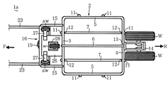
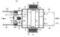
図5は、本考案による第2の農作業用キャリア1bを示す斜視図であり、図6は、その一部を省略した底面図である。
係る農作業用キャリア1bは、図5,図6に示すように、前記同様の荷台枠2、荷支え枠8,9、左右一対の支え枠15、丁番金具16、握り枠24を含む左右一対の牽引枠23、台座26、前輪w、および一対の補助輪awを備えている。
係る農作業用キャリア1bが前記第1の農作業用キャリア1aと異なるのは、図5,図6に示すように、荷台枠2における左右一対の側枠5の外側ごとに、垂直断面が逆L字形状の車輪カバー33が固定され、それらの縦板34の外側に前記同様の後輪Wが軸支されると共に、該一対の縦板34間には、荷台枠2の幅方向に沿った水平な荷支持板30が、その両端の各縦片31を介して固定されている。
FIG. 5 is a perspective view showing a
As shown in FIGS. 5 and 6, the
The
また、前記車輪カバー33ごとの上面には、前後一対の縦片11を含む左右一対の荷支え枠10が個別に立設されている。
更に、前記荷台枠2における左右一対の側枠5間には、前記荷支持板30を挟んで前後一対の荷支持枠32が互いに平行に架け渡されている。
上記のような農作業用キャリア1bも、前記と同じ極く簡単な操作によって、図6中の一点鎖線で示すように、握り枠24を含む左右一対の牽引枠23を、荷台枠2の上方に折り畳むことができる。この際、左右一対の牽引枠23も後枠5に接触した状態で停止すると共に、係る一対の牽引枠23間から、前記荷支え枠8,9を立設させることができる。
以上のような第2の農作業用キャリア1bによっても、前記効果(1)〜(5)を確実に奏することが可能である。
A pair of left and right load support frames 10 including a pair of front and rear
Further, between the pair of left and right side frames 5 in the
The
The above effects (1) to (5) can be surely achieved by the
本考案は、以上において説明した形態に限定されるものではない。
例えば、前記荷台枠2、荷支え枠8〜10,支持枠15、および牽引枠23は、エンジニアリングプラスチックなどの硬質樹脂の枠材により形成しても良い。
また、前記荷支え枠8〜10の上片には、緩衝用の樹脂管やゴム管を巻き付けても良い。
更に、前記台座26の底面に左右一対の前輪wを取り付けた場合、前記左右一対の補助輪awを省略しても良い。
加えて、前記牽引枠23、荷台枠2、および一対の後輪W付近に対して、公知のブレーキ機構を付設するようにしても良い。
The present invention is not limited to the form described above.
For example, the
Further, a buffer resin tube or a rubber tube may be wound around the upper piece of the load support frame 8-10.
Furthermore, when the pair of left and right front wheels w are attached to the bottom surface of the
In addition, a known brake mechanism may be attached to the vicinity of the pulling
本考案の農作業用キャリアによれば、丈の低い収穫用容器などの積荷であっても容易に荷台枠に荷上げしたり、荷降ろしでき、不使用時には極く簡単且つ迅速な操作でコンパクトに折り畳めると共に、簡素な構造で且つ構成部材数を少なくした農作業用キャリアを低コストで確実に提供することができる。 According to the carrier for agricultural work of the present invention, even a load such as a harvesting container with a low height can be easily loaded and unloaded on the carrier frame, and when not in use, it can be compacted with extremely simple and quick operation. The carrier for farm work which can be folded and has a simple structure and a reduced number of components can be reliably provided at low cost.
1a,1b…農作業用キャリア
2……………荷台枠
3……………前枠
4……………後枠
5……………側枠
8〜10……荷支え枠
16…………丁番金具
17…………回転金具(一方)
23…………牽引枠
24…………握り枠
26…………台座
33…………車輪カバー
W……………後輪
w……………前輪
aw…………補助輪
1a, 1b ...
23 ………… Towing
Claims (4)
上記後枠(4)における水平方向の中間から後方(R)に延びた支持枠(14)に軸支される左右一対の後輪(W)と、
上記荷台枠(2)の前枠(3)、後枠(4)、および左右一対の側枠(5)ごとにおける水平方向の中間から立設した前後左右4つの荷支え枠(8,9,10)と、
上記前枠(3)の前方に水平状に張り出した台座(26)の底面に取り付けられた1つまたは2つの方向自在な前輪(w)と、
上記荷台枠(2)の前枠(3)から斜め前方(F)に延びた一対の支持枠(15)の前端側に固定された丁番金具(16)と、
上記丁番金具(16)の一方(17)に基端側を回転可能に取り付けられ、且つ先端に位置する水平な握り枠(24)によって連結された左右一対の牽引枠(23)と、を備えた農作業用キャリア(1a)であって、
上記左右一対の牽引枠(23)は、上記荷台枠(2)側から離れ且つ斜め前方(F)に延びた牽引時から、それらの基端側を回転中心として後方(R)に回転させた際に、上記荷台枠(2)の後枠(4)に接して支持されると共に、上記前枠(3)および後枠(4)ごとの上記前後一対の荷支え枠(8,9)を当該一対の牽引枠(23)の間から立設させる、
ことを特徴とする農作業用キャリア(1a)。 A carrier frame (2) having a rectangular outer shape in plan view and including a front frame (3), a rear frame (4), and a pair of left and right side frames (5);
A pair of left and right rear wheels (W) pivotally supported by a support frame (14) extending rearward (R) from a horizontal middle in the rear frame (4);
Four front and rear left and right load support frames (8, 9,...) Erected from the middle in the horizontal direction for each of the front frame (3), rear frame (4), and left and right side frames (5) of the load carrier frame (2). 10) and
One or two directional front wheels (w) attached to the bottom surface of a pedestal (26) extending horizontally in front of the front frame (3);
A hinge bracket (16) fixed to the front end side of a pair of support frames (15) extending obliquely forward (F) from the front frame (3) of the load carrier frame (2);
A pair of left and right traction frames (23) attached to one (17) of the hinge bracket (16) so that the base end side is rotatable and connected by a horizontal gripping frame (24) located at the distal end. A farm carrier (1a) provided with
The pair of left and right traction frames (23) are rotated rearward (R) with their base end sides as the center of rotation from the time of traction which is separated from the loading frame (2) side and extends obliquely forward (F). The pair of front and rear load support frames (8, 9) for each of the front frame (3) and the rear frame (4) are supported while being in contact with the rear frame (4) of the load carrier frame (2). Erect from between the pair of tow frames (23),
A farm carrier (1a) characterized by that.
上記左右一対の側枠(5)ごとの外側に軸支された左右一対の後輪(W)と、
上記荷台枠(2)の前枠(3)および後枠(4)における水平方向の中間から立設した前後一対の荷支え枠(8,9)、および上記左右一対の後輪(W)の車輪カバー(33)ごとの上面から立設した左右一対の荷支え枠(10)と、
上記前枠(3)の前方に水平状に張り出した台座(26)の底面に取り付けられた1つまたは2つの方向自在な前輪(w)と、
上記荷台枠(2)の前枠(3)から斜め前方(F)に延びた一対の支持枠(15)の前端側に固定された丁番金具(16)と、
上記丁番金具(16)の一方(17)に基端側を回転可能に取り付けられ、且つ先端に位置する水平な握り枠(24)によって連結された左右一対の牽引枠(23)と、を備えた農作業用キャリア(1b)であって、
上記左右一対の牽引枠(23)は、上記荷台枠(2)側から離れ且つ斜め前方(F)に延びた牽引時から、それらの基端側を回転中心として後方(R)に回転させた際に、上記荷台枠(2)の後枠(4)に接して支持されると共に、該荷台枠(2)の前枠(3)および後枠(4)ごとの上記前後一対の荷支え枠(8,9)を当該一対の牽引枠(23)の間から立設させる、
ことを特徴とする農作業用キャリア(1b)。 A carrier frame (2) having a rectangular outer shape in plan view and including a front frame (3), a rear frame (4), and a pair of left and right side frames (5);
A pair of left and right rear wheels (W) pivotally supported on the outside of each of the pair of left and right side frames (5);
A pair of front and rear load support frames (8, 9) erected from the horizontal middle of the front frame (3) and the rear frame (4) of the load carrier frame (2), and the pair of left and right rear wheels (W) A pair of left and right load support frames (10) erected from the upper surface of each wheel cover (33);
One or two directional front wheels (w) attached to the bottom surface of a pedestal (26) extending horizontally in front of the front frame (3);
A hinge bracket (16) fixed to the front end side of a pair of support frames (15) extending obliquely forward (F) from the front frame (3) of the load carrier frame (2);
A pair of left and right traction frames (23) attached to one (17) of the hinge bracket (16) so that the base end side is rotatable and connected by a horizontal gripping frame (24) located at the distal end. A farming carrier (1b) provided,
The pair of left and right traction frames (23) are rotated rearward (R) with their base end sides as the center of rotation from the time of traction which is separated from the loading frame (2) side and extends obliquely forward (F). In this case, the pair of front and rear load support frames for each of the front frame (3) and the rear frame (4) of the load carrier frame (2) are supported in contact with the rear frame (4) of the load carrier frame (2). (8, 9) is erected from between the pair of traction frames (23),
A farm carrier (1b) characterized by that.
ことを特徴とする請求項1または2に記載の農作業用キャリア(1a,1b)。 The four load-supporting frames (8, 9, 10) exhibit a shape protruding outward (11) or a circular arc shape in a side view,
Agricultural work carrier (1a, 1b) according to claim 1 or 2, characterized in that.
ことを特徴とする請求項1乃至3の何れか一項に記載の農作業用キャリア(1a,1b)。 There is one directional front wheel (w), and a pair of left and right auxiliary wheels (aw) extending obliquely downward and outward are attached to both sides of the front wheel (w) via the pedestal (26). ing,
The carrier for farm work (1a, 1b) according to any one of claims 1 to 3, wherein the carrier is used for farm work.
Priority Applications (1)
| Application Number | Priority Date | Filing Date | Title |
|---|---|---|---|
| JP2015004935U JP3201493U (en) | 2015-09-29 | 2015-09-29 | Agricultural carrier |
Applications Claiming Priority (1)
| Application Number | Priority Date | Filing Date | Title |
|---|---|---|---|
| JP2015004935U JP3201493U (en) | 2015-09-29 | 2015-09-29 | Agricultural carrier |
Publications (1)
| Publication Number | Publication Date |
|---|---|
| JP3201493U true JP3201493U (en) | 2015-12-10 |
Family
ID=54784267
Family Applications (1)
| Application Number | Title | Priority Date | Filing Date |
|---|---|---|---|
| JP2015004935U Expired - Fee Related JP3201493U (en) | 2015-09-29 | 2015-09-29 | Agricultural carrier |
Country Status (1)
| Country | Link |
|---|---|
| JP (1) | JP3201493U (en) |
Cited By (1)
| Publication number | Priority date | Publication date | Assignee | Title |
|---|---|---|---|---|
| JP7611624B1 (en) * | 2024-07-26 | 2025-01-10 | 株式会社高橋仮設 | Cart System |
-
2015
- 2015-09-29 JP JP2015004935U patent/JP3201493U/en not_active Expired - Fee Related
Cited By (1)
| Publication number | Priority date | Publication date | Assignee | Title |
|---|---|---|---|---|
| JP7611624B1 (en) * | 2024-07-26 | 2025-01-10 | 株式会社高橋仮設 | Cart System |
Similar Documents
| Publication | Publication Date | Title |
|---|---|---|
| US9758184B1 (en) | Three wheel cargo cart with lifting drawbar | |
| US8087678B2 (en) | Combination cart and stand device | |
| US9586637B2 (en) | Cart assembly | |
| US8141888B1 (en) | Surfboard transportation device | |
| US3659867A (en) | Foldable tow-wheel dolly | |
| US2767996A (en) | Collapsible lawn cart | |
| EP2528799B1 (en) | Platform truck having a platform that can be upwardly pivoted from two sides | |
| US9889786B1 (en) | Pivotal loading apparatus for a tailgate | |
| CN109963801A (en) | Hose conveying cart | |
| US6604749B2 (en) | Carcass transportation device | |
| JP3201493U (en) | Agricultural carrier | |
| US9845100B2 (en) | Trolley for transporting loads | |
| US12319359B1 (en) | Pivotable and nestable cargo rack for truck bed or trailer | |
| US3421644A (en) | Method and apparatus for transporting grain bins | |
| US8333249B1 (en) | Portable field roller device | |
| JP3199048U (en) | Agricultural carrier | |
| JP2005271687A (en) | Conveying carriage device | |
| US4103831A (en) | Bale handling device | |
| JP3195677U (en) | Agricultural carrier | |
| KR101840524B1 (en) | Device for lifting and unloading the box | |
| JP3188684U (en) | Agricultural transporter | |
| KR200459780Y1 (en) | A handcart for broccoli harvest | |
| JP3215124U (en) | Agricultural carrier | |
| JPH0718703Y2 (en) | Lifting stand for truck container | |
| US6068434A (en) | Positive locking multiple bale transporting device |
Legal Events
| Date | Code | Title | Description |
|---|---|---|---|
| R150 | Certificate of patent or registration of utility model |
Ref document number: 3201493 Country of ref document: JP Free format text: JAPANESE INTERMEDIATE CODE: R150 |
|
| R250 | Receipt of annual fees |
Free format text: JAPANESE INTERMEDIATE CODE: R250 |
|
| R250 | Receipt of annual fees |
Free format text: JAPANESE INTERMEDIATE CODE: R250 |
|
| LAPS | Cancellation because of no payment of annual fees |