JP3201760U - jig - Google Patents
jig Download PDFInfo
- Publication number
- JP3201760U JP3201760U JP2015005217U JP2015005217U JP3201760U JP 3201760 U JP3201760 U JP 3201760U JP 2015005217 U JP2015005217 U JP 2015005217U JP 2015005217 U JP2015005217 U JP 2015005217U JP 3201760 U JP3201760 U JP 3201760U
- Authority
- JP
- Japan
- Prior art keywords
- jig
- positioning surface
- steel material
- positioning
- bearing plate
- Prior art date
- Legal status (The legal status is an assumption and is not a legal conclusion. Google has not performed a legal analysis and makes no representation as to the accuracy of the status listed.)
- Expired - Lifetime
Links
Images




Landscapes
- Connection Of Plates (AREA)
Abstract
【課題】鋼材に対して軸受板を高精度に取付けることができる治具を提供すること。【解決手段】治具本体22には、第1位置決め面231と、その第1位置決め面231に対して直角をなす第2位置決め面311とが形成されている。前記第2位置決め面311に対して前記第1位置決め面を介した反対側には、基準孔33を有する一対の平行な基準板32が備えられ、前記基準孔33に挿入される基準ピン36が備えられている。【選択図】図5To provide a jig capable of attaching a bearing plate to a steel material with high accuracy. A jig body has a first positioning surface and a second positioning surface that is perpendicular to the first positioning surface. A pair of parallel reference plates 32 having a reference hole 33 is provided on the opposite side of the second positioning surface 311 with respect to the first positioning surface, and a reference pin 36 inserted into the reference hole 33 is provided. Is provided. [Selection] Figure 5
Description
本考案は、例えば、鋼材の端部に軸受け板を取付けるために用いられる治具に関するものである。 The present invention relates to a jig used for attaching a bearing plate to an end portion of a steel material, for example.
例えば、特許文献1には、図11に示すように、コンクリート覆工型枠101が開示されている。このコンクリート覆工型枠101は、トンネルの内周面に打設されるコンクリートを成形するためのものである。
For example, Patent Document 1 discloses a
前記型枠101は、複数の型枠部材102によって構成されるが、コンクリートの硬化後の脱型時に、型枠部材102を蝶番の作用によってトンネルの中心側に折り畳むことができるように構成される。
The
前記の構成の場合、蝶番の軸が支持される軸受板と、型枠部材との間における位置関係の精度が低いと、コンクリートの打設面の仕上がりに悪影響が与えられる。
本考案の目的は、鋼材に対して軸受板を高精度に取付けることができる治具を提供することにある。
In the case of the above configuration, if the accuracy of the positional relationship between the bearing plate on which the hinge shaft is supported and the formwork member is low, the finish of the concrete placement surface is adversely affected.
An object of the present invention is to provide a jig capable of attaching a bearing plate to a steel material with high accuracy.
上記の目的を達成するために、本考案において、治具本体には、第1位置決め面と、その第1位置決め面に対して直角をなす第2位置決め面とが形成され、前記第2位置決め面に対して前記第1位置決め面を介した反対側には、基準部材が備えられ、その基準部材は、前記第1位置決め面及び第2位置決め面と平行な中心軸線上に位置する基準孔を有し、さらに、前記基準孔に挿入される基準ピンが備えられたことを特徴とする。 In order to achieve the above object, in the present invention, the jig body is formed with a first positioning surface and a second positioning surface perpendicular to the first positioning surface, and the second positioning surface. A reference member is provided on the opposite side of the first positioning surface with respect to the first positioning surface, and the reference member has a reference hole located on a central axis parallel to the first positioning surface and the second positioning surface. In addition, a reference pin inserted into the reference hole is provided.
以上の構成においては、軸受板が鋼材に対して軸孔を基準にして、高精度な位置関係をもって固定される。このため、鋼材が軸孔を通る軸を介して他の鋼材に組付けられる場合、言い換えれば、鋼材どうしが相互に組み付けられる場合、高い組付け精度を得ることができる。 In the above configuration, the bearing plate is fixed to the steel material with a highly accurate positional relationship with respect to the shaft hole. For this reason, when steel materials are assembled | attached to another steel material via the axis | shaft which passes along a shaft hole, in other words, when steel materials are mutually assembled | attached, a high assembly | attachment precision can be obtained.
以上のように、本考案によれば、鋼材に対して軸受板を高精度に取付けることができるという効果を発揮する。 As described above, according to the present invention, the bearing plate can be attached to the steel material with high accuracy.
以下、本考案を具体化した各実施形態を図面に基づいて説明する。
(第1実施形態)
図1〜図7に基づいて第1実施形態を説明する。
Hereinafter, each embodiment which materialized this invention is described based on a drawing.
(First embodiment)
1st Embodiment is described based on FIGS.
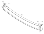
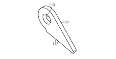
図1及び図2に示すように、H型鋼よりなるワークとしての鋼材110の両端部フランジには、それぞれ軸孔113を有する軸受板111が溶接によって固着されている。
図3及び図4に示すように、本実施形態の治具21の治具本体22は、全体が板材によって構成され、基板部23と、その基板部23の両端に固着された支持板部24,25とを備えている。基板部23の側面が第1位置決め面231になっている。基板部23の両側部には透孔29が形成されている。また、基板部23の両側には取付部27が突出形成され、この取付部27にはそれぞれ複数の取付孔28が透設されている。
As shown in FIGS. 1 and 2, bearing
As shown in FIGS. 3 and 4, the jig
一方の支持板部25の外側面(図の下端)には、一対の位置決め部材31が溶接によって固着されており、この位置決め部材31の基板部23側の面311と前記第1位置決め面231とは直角をなしている。この面311を第2位置決め面311とする。
A pair of
支持板部24に形成した孔241には一対の平行をなす基準板32の脚部321が挿入されており、この脚部321の幅端部が基板部23の内面に当接されるとともに、図示下端が支持板部25の内面に当接されている。脚部321は、基板部23,支持板部24,25に溶接され、基板部23,支持板部24,25に対する補強作用を果たしている。この基準板32の図示上端部の同位置には、基準孔33が透設されている。この基準孔33は、前記第1,第2位置決め面231,311と平行な中心軸線を有する。また、図6に示すように、基準板32間の空間の間隔Wは、後述する軸受板111の厚さTと等しいか、その厚さTよりわずかに狭く形成されている。
A pair of
図7に示すように、本実施形態においては、前記基準孔33に挿入される基準ピン36が備えられている。
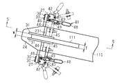
図5及び図6に示すように、本実施形態においては、周知のクランプ具41が用いられる。このクランプ具41は、前記取付部27の透孔29にボルト30及びナット35によって固定されるベース42と、そのベース42に軸43により回転可能に支持され、先端部に押さえ部材44を有する押さえレバー45と、ベース42に軸46によって回転可能に支持され、中間部において軸49を介して押さえレバー45に連結されたロックレバー48とを有する。
As shown in FIG. 7, in this embodiment, a
As shown in FIGS. 5 and 6, a known
次に、以上のように構成された治具21を用いて、鋼材110に対して図2に示す1枚の軸受板111を取付ける場合の取付け方法について説明する。
あらかじめ、基板部23の両取付部27にクランプ具41をボルト30及びナット35により取付ける。次いで、鋼材110の端面の端板114に治具21の基板部23の第1位置決め面231を当てるとともに、鋼材110のフランジに位置決め部材31の第2位置決め面311を当てる。
Next, a mounting method in the case where one bearing
In advance, the
これによって、治具21が鋼材110の端部に対して2位置で位置決めされる。この状態においては、基準板32の基準孔33が鋼材110に対する所定箇所に位置する。そして、この位置決め状態で、クランプ具41の押さえレバー45を回転させて、押さえ部材44を鋼材110の端板114に当てる。この状態で、ロックレバー48を回転させれば、そのロックレバー48がデッドポイントを越えて、押さえ部材44が前記端板114に圧接される。このため、押さえ部材44と基板部23との間に端板114が挟持されて、治具21が前記の位置決め状態で鋼材110に固定される。このとき、必要に応じて、前記端板114の孔(図示しない)と基板部23の透孔29とにボルト50が挿通されて、ナット51が締め付けられる。
Thereby, the
そして、2枚の基準板32間に、軸受板111を挟持して、軸受板111の取付縁112を鋼材110のフランジ上に定置する。このとき、両基準板32間の空間の間隔Wが軸受板111の厚さTと等しいか、厚さTよりわずかに狭くなっているため、軸受板111は、傾いたりすることなく、安定して鋼材110のフランジ上に定置される。
Then, the
次いで、図5及び図7に示すように、基準板32の基準孔33と軸受板111の軸孔113に基準ピン36を挿通させれば、前記基準孔33を基準にして、軸受板111の軸孔113が鋼材110の所定位置に位置決めされる。この状態で、軸受板111と鋼材とを溶接すれば、鋼材110と軸受板111とが軸受板111の軸孔113を基準とした位置決め状態で固定される。
Next, as shown in FIGS. 5 and 7, if the
従って、本実施形態においては、以下の効果がある。
(1)軸受板111が鋼材110に対して軸孔113を基準にして、高精度な位置関係をもって固定される。このため、鋼材110が軸孔113を通る軸を介して他の鋼材を組付けられる場合、言い換えれば、鋼材110が蝶番を介して他の鋼材に組み付けられる場合、その他の鋼材に対する高い組付け精度を得ることができる。
Therefore, this embodiment has the following effects.
(1) The
(2)治具21には直角をなす第1、第2位置決め面231,311が形成されている。このため、治具21を鋼材110の所定位置に当てるだけで、鋼材110と治具21とを位置決めでき、この状態で基準ピン36を用いて軸受板111の軸孔113を位置決めできて、鋼材110に対する軸受板111の溶接も容易かつ高精度に行なうことができる。
(2) First and
(3)治具21にクランプ具41を取り付けることができるようにしたことにより、クランプ具41により、治具21を鋼材110に対して安定して固定でき、軸受板111を正確な位置に安定して設置できる。
(3) By allowing the
(第2実施形態)
次に、本考案を具体化した第2実施形態を説明する。
本実施形態は、図1及び図9に示すように、鋼材110の端部のフランジ上に2枚の軸受板111を互いに平行に固着できるようにしたものである。
(Second Embodiment)
Next, a second embodiment that embodies the present invention will be described.
In this embodiment, as shown in FIGS. 1 and 9, two bearing
そのため、図8及び10に示すように、治具21の基準板32は1枚設けられ、その両側面にスペーサ34がそれぞれ交換可能に固着されている。両スペーサ34間の外側面間の距離は、鋼材110上に取り付けられた状態の一対の軸受板111間の空間の間隔Wと等しくなっている。従って、軸受板111の厚さに応じて、適当な厚さのスペーサ34が用いられる。
Therefore, as shown in FIGS. 8 and 10, one
従って、鋼材110に対する軸受板111に設置においては、図10に示すように、鋼材110に位置決め固定された状態の基準板32の両側に対し、軸受板111を配置して、基準板32を挟んだ状態の両軸受板111間をクランプ(図示しない)によって挟持すれば、軸受板111は、鋼材110の所定位置に位置決めされるため、この状態で、軸受板111を鋼材110に対して溶接すればよい。
Therefore, when installing the
本実施形態においては、前記第1実施形態と同様な効果を得ることができる。
(変更例)
本考案は、前記実施形態に限定されるものではなく、以下のような態様で具体化してもよい。
In the present embodiment, the same effect as in the first embodiment can be obtained.
(Example of change)
The present invention is not limited to the above embodiment, and may be embodied in the following manner.
・前記第1実施形態において、両基準板32の対向する側面にスペーサを着脱可能に設けることができるようにすること。このようにすれば、軸受板111の厚さが変化した場合、スペーサを交換することで、その厚さの変化に対処できる。
In the first embodiment, spacers can be detachably provided on the opposite side surfaces of both
・クランプ具41を取り付けるための取付部27を省略すること。このように構成した場合は、治具21の基板部23と鋼材110の端板114とがクランプ具によってクランプされる。
-The
・前記第2実施形態において、基準板32の両スペーサ34のうちの少なくとも一方を省略すること。
In the second embodiment, at least one of the
21…治具、22…治具本体、23…基板部、27…取付部、31…位置決め部材、32…基準板、33…基準孔、34…スペーサ、36…基準ピン、41…クランプ具、231…第1位置決め面、311…第2位置決め面。
DESCRIPTION OF
Claims (5)
前記第2位置決め面に対して前記第1位置決め面を介した反対側には、基準部材が備えられ、
その基準部材は、前記第1位置決め面及び第2位置決め面と平行な中心軸線上に位置する基準孔を有し、
さらに、前記基準孔に挿入される基準ピンが備えられた治具。 The jig body is formed with a first positioning surface and a second positioning surface perpendicular to the first positioning surface,
A reference member is provided on the opposite side of the second positioning surface via the first positioning surface,
The reference member has a reference hole located on a central axis parallel to the first positioning surface and the second positioning surface,
Furthermore, the jig | tool provided with the reference | standard pin inserted in the said reference | standard hole.
Priority Applications (1)
| Application Number | Priority Date | Filing Date | Title |
|---|---|---|---|
| JP2015005217U JP3201760U (en) | 2015-10-15 | 2015-10-15 | jig |
Applications Claiming Priority (1)
| Application Number | Priority Date | Filing Date | Title |
|---|---|---|---|
| JP2015005217U JP3201760U (en) | 2015-10-15 | 2015-10-15 | jig |
Publications (1)
| Publication Number | Publication Date |
|---|---|
| JP3201760U true JP3201760U (en) | 2015-12-24 |
Family
ID=54933124
Family Applications (1)
| Application Number | Title | Priority Date | Filing Date |
|---|---|---|---|
| JP2015005217U Expired - Lifetime JP3201760U (en) | 2015-10-15 | 2015-10-15 | jig |
Country Status (1)
| Country | Link |
|---|---|
| JP (1) | JP3201760U (en) |
Cited By (2)
| Publication number | Priority date | Publication date | Assignee | Title |
|---|---|---|---|---|
| JP2018167307A (en) * | 2017-03-30 | 2018-11-01 | 有限会社 伊藤 | Positioning method of end plate to die steel, and jig for fixing end plate to die steel |
| JP2020070604A (en) * | 2018-10-31 | 2020-05-07 | 有限会社 伊藤 | Method and apparatus for manufacturing steel member |
-
2015
- 2015-10-15 JP JP2015005217U patent/JP3201760U/en not_active Expired - Lifetime
Cited By (3)
| Publication number | Priority date | Publication date | Assignee | Title |
|---|---|---|---|---|
| JP2018167307A (en) * | 2017-03-30 | 2018-11-01 | 有限会社 伊藤 | Positioning method of end plate to die steel, and jig for fixing end plate to die steel |
| JP2020070604A (en) * | 2018-10-31 | 2020-05-07 | 有限会社 伊藤 | Method and apparatus for manufacturing steel member |
| JP7005014B2 (en) | 2018-10-31 | 2022-01-21 | 有限会社 伊藤 | Steel manufacturing equipment |
Similar Documents
| Publication | Publication Date | Title |
|---|---|---|
| US9242348B2 (en) | Interlocking clamp | |
| JP6041769B2 (en) | Stud welding positioning jig | |
| WO2011132506A1 (en) | Welding jig and welding method using the same | |
| KR102142201B1 (en) | Wedge drive | |
| JP6734156B2 (en) | Anchor fixing structure and anchor fixing method | |
| JP2017142108A (en) | Specimen type frame for concrete bending strength test | |
| JP6403165B2 (en) | Manufacturing method and jig for structural material | |
| JP2011153868A (en) | Jig for equipment for testing characteristics of rubber bush | |
| JP2017075501A5 (en) | ||
| JP6614676B2 (en) | Fixing jig for end plate against mold steel | |
| JP2015071938A (en) | Template and fixing plate for assembling post reinforced with reinforcing steels | |
| JP2016156390A (en) | Aluminum frame assembly jig | |
| JP5379737B2 (en) | Misalignment correction jig | |
| JP7569769B2 (en) | WELD END SURFACE CONFIGURATION MEMBER AND METHOD FOR JOINING COLUMNS USING WELD END SURFACE CONFIGURATION MEMBER | |
| CN103217514A (en) | Eccentricity vertical loading device acting on column | |
| KR101608041B1 (en) | jig assembly for clamping a large size disc goods | |
| JP7005014B2 (en) | Steel manufacturing equipment | |
| CN211991587U (en) | Landing leg dish welding set | |
| JP7062575B2 (en) | Jig for drilling holes in steel pipes and drilling methods | |
| CN215888978U (en) | Steel bar fixture capable of being rapidly positioned | |
| JP6284214B1 (en) | Temporary fixing bracket for floor slab construction | |
| JPH04277266A (en) | Installing frame of square with base | |
| JP2017125327A (en) | jig | |
| JP4746751B2 (en) | Anchor bolt support | |
| KR102390128B1 (en) | Jig for fixing welding object |
Legal Events
| Date | Code | Title | Description |
|---|---|---|---|
| R150 | Certificate of patent or registration of utility model |
Ref document number: 3201760 Country of ref document: JP Free format text: JAPANESE INTERMEDIATE CODE: R150 |
|
| R250 | Receipt of annual fees |
Free format text: JAPANESE INTERMEDIATE CODE: R250 |
|
| R250 | Receipt of annual fees |
Free format text: JAPANESE INTERMEDIATE CODE: R250 |
|
| R250 | Receipt of annual fees |
Free format text: JAPANESE INTERMEDIATE CODE: R250 |
|
| EXPY | Cancellation because of completion of term |