JP3206702U - Power line communication device - Google Patents
Power line communication device Download PDFInfo
- Publication number
- JP3206702U JP3206702U JP2016003490U JP2016003490U JP3206702U JP 3206702 U JP3206702 U JP 3206702U JP 2016003490 U JP2016003490 U JP 2016003490U JP 2016003490 U JP2016003490 U JP 2016003490U JP 3206702 U JP3206702 U JP 3206702U
- Authority
- JP
- Japan
- Prior art keywords
- signal
- processing unit
- traffic
- power line
- central processing
- Prior art date
- Legal status (The legal status is an assumption and is not a legal conclusion. Google has not performed a legal analysis and makes no representation as to the accuracy of the status listed.)
- Expired - Fee Related
Links
Images




Landscapes
- Cable Transmission Systems, Equalization Of Radio And Reduction Of Echo (AREA)
- Traffic Control Systems (AREA)
Abstract
【課題】交通制御設備の電力線通信装置を提供する。【解決手段】電力線通信装置は、交通信号制御装置1の信号を2芯の電力線5を用いて、交通設備4を制御しており、交通信号制御設備1に接続された符号化装置2と、交通設備4に接続された復号化装置3と、を含む。符号化装置2および復号化装置3は、それぞれ回路基板に設けられて、2芯の電力線5で接続される。符号化装置2および復号化装置3は、それぞれプロトコル信号の処理ユニット216、316と、電源供給器214、314と、CPU演算のPLC中央処理ユニット211、311と、IP/ID編集識別信号処理ユニット213、317と信号変換処理ユニット217、313と、を含む。【選択図】図3A power line communication device for traffic control equipment is provided. A power line communication apparatus controls a traffic facility using a signal from a traffic signal control device using a two-core power line, and an encoding device connected to the traffic signal control facility. And a decoding device 3 connected to the traffic facility 4. The encoding device 2 and the decoding device 3 are each provided on a circuit board and connected by a two-core power line 5. The encoding device 2 and the decoding device 3 include protocol signal processing units 216 and 316, power supply units 214 and 314, CPU arithmetic PLC central processing units 211 and 311 and IP / ID editing identification signal processing units, respectively. 213 and 317 and signal conversion processing units 217 and 313. [Selection] Figure 3
Description
本考案は、電力線通信装置装置であって、特に、交通の電力線通信の応用に関する。 The present invention relates to a power line communication device, and more particularly to an application of traffic power line communication.
既存の交通設備と交通信号制御装置は、電力線と信号線とが別々であって、電力線が動力供給の伝達し、信号線が信号を伝達する。例えば、交通信号灯の駆動において、もし車両の走行方向は、5つの交通信号灯(例えば、左折矢印の信号灯、直進矢印の信号灯、右折矢印の信号灯、黄色の信号灯、赤い信号灯)の場合、駆動電力線として、6芯の電力線が必要である。 In the existing traffic equipment and the traffic signal control device, the power line and the signal line are separate, the power line transmits the power supply, and the signal line transmits the signal. For example, when driving a traffic signal light, if the vehicle travel direction is five traffic signal lights (for example, a left turn arrow signal light, a straight arrow signal light, a right turn arrow signal light, a yellow signal light, a red signal light), A 6-core power line is required.
もし交差道路のロービームとハイビームが、すべて1つのライトが一線で制御することを採用すれば、十字形の交差道路口では、約48本の信号線が、交通信号の制御機端に接続される。また、交通信号のカウントダウンの通信回線と監視等は、平時のメンテナンスにおいて、多すぎるケーブルが、ハングの状態となり、さらに、走行する中の車両に掛けられる可能性があり、セキュリティの危険性が生じる虞がある。
本考案は、上述の課題に鑑みてなされたものであり、その目的は、電力線通信装置を提供することにある。
If the low beam and the high beam of the crossing road are all controlled by one light, about 48 signal lines are connected to the traffic signal controller end at the cross-shaped intersection road entrance. . In addition, traffic signal countdown communication lines and monitoring, etc., can cause a security risk because too many cables may hang during normal maintenance, and may be hung on a running vehicle. There is a fear.
This invention is made | formed in view of the above-mentioned subject, The objective is to provide a power line communication apparatus.
本考案は、電力線通信装置であって、交通信号制御装置の信号を2芯の電力線を用いて、交通設備を制御しており、交通信号制御装置に接続された符号化装置と、交通設備に接続された復号化装置と、を含む。符号化装置および復号化装置は、それぞれ回路基板に設けられて、2芯の電力線で接続される。符号化装置および復号化装置は、それぞれプロトコル信号の処理ユニットと、電源供給器と、CPU演算のPLC中央処理ユニットと、IP/ID編集識別信号処理ユニットと信号変換処理ユニットと、を含む。 The present invention is a power line communication device that controls traffic equipment using a signal of a traffic signal control device using a two-core power line, and includes a coding device connected to the traffic signal control device and a traffic equipment. And a connected decryption device. The encoding device and the decoding device are each provided on a circuit board and connected by a two-core power line. The encoding device and the decoding device each include a protocol signal processing unit, a power supply, a CPU arithmetic PLC central processing unit, an IP / ID edit identification signal processing unit, and a signal conversion processing unit.
CPU演算のPLC中央処理ユニットでそれぞれに交通信号制御装置のライト出力の電力信号とプロトコル信号を処理した後、ライト出力の電力信号が、出力する方法で2芯の電力線に編集されて、2芯の電力線を介して、符号化装置に伝送されて接続し、符号化装置を介して、交通信号制御装置に伝送され、それによって、交通信号制御装置が電源を出力する時、プロトコル信号のメーセッジを交通信号制御装置の電源にコンパイルさせて、それを電源の所に伝送する。 After processing the light output power signal and the protocol signal of the traffic signal control device in each PLC central processing unit of CPU calculation, the power signal of the light output is edited into a 2-core power line by the output method, and the 2-core Is transmitted to and connected to the encoding device via the power line, and is transmitted to the traffic signal control device via the encoding device, so that when the traffic signal control device outputs power, the protocol signal message is transmitted. Compile the traffic signal controller power supply and transmit it to the power supply.
本考案による電力線通信装置を図面に基づいて説明する。以下、複数の実施形態において、実質的に同一の構成には同一の符号を付して説明を省略する。
本考案の実施形態では、交通制御端と設備端との通信及びその関連信号を電力線通信(Power Line Communication、PLC)技術のロジックを応用したものである。本装置のCPUによって、迅速かつ効果的に生成信号を集め、送信して、データのコンパイル信号を管理して、しかも当該交通設備の電力供給ネットワークに送信させる。また、元の駆動設備の電力線を使用して、データ信号のチャネルとし、交通の電力通信ネットワークを作って、既存の交通施設に関連する多くの駆動線路と信号伝送線路の機能を取り換えて、交通制御端から設備作動端までの配線機能を減少及び取り換える。
A power line communication apparatus according to the present invention will be described with reference to the drawings. Hereinafter, in a plurality of embodiments, the same numerals are given to the substantially same composition, and explanation is omitted.
In the embodiment of the present invention, the communication between the traffic control end and the facility end and the related signal are applied to the logic of the power line communication (PLC) technology. The CPU of this device collects and transmits the generated signals quickly and effectively, manages the data compilation signals, and transmits them to the power supply network of the traffic facility. In addition, the power line of the original drive equipment is used as a data signal channel, a traffic power communication network is created, and the functions of many drive lines and signal transmission lines related to existing traffic facilities are replaced. Reduce and replace the wiring function from the control end to the equipment operating end.
本考案の主な目的は、電力線通信装置により、交通設備及び信号制御設備における秒数カウントダウンは、より正確になる。交通信号制御装置と接続した符号化装置と復号化装置を利用して、符号化装置と復号化装置との間に接続している2芯の電力線で、交通制御端と設備端との通信及びその関連駆動信号を電力線通信(Power Line Communication、PLC)技術のロジックな応用で、迅速かつ効果的に生成信号を集め、送信して、データのコンパイル信号を管理して、しかも当該交通設備の電力供給ネットワークに送信させて、それによって、正確に秒数カウントダウンの関連信号を伝送できる。 The main object of the present invention is to make the countdown of seconds in traffic facilities and signal control facilities more accurate due to the power line communication device. Communication between the traffic control end and the facility end using a two-core power line connected between the encoding device and the decoding device using the encoding device and the decoding device connected to the traffic signal control device; The related drive signal is a logic application of Power Line Communication (PLC) technology, and the generated signals are collected and transmitted quickly and effectively, the compiled signal of the data is managed, and the power of the relevant transportation equipment It can be sent to the supply network, thereby accurately transmitting the relevant signal with a countdown of seconds.
本考案の次の目的は、電力線通信装置を利用して、元の駆動設備の電力線を使用してデータ信号のチャネルとさせて、交通の電力通信線を作って、既存の交通施設に関連する多くの駆動線路と信号伝送線路の機能を取り換えて、交通制御端から設備作動端までの道路配線機能を減少及び取り換える。 The next object of the present invention is to use a power line communication device, use the power line of the original driving equipment as a data signal channel, create a traffic power communication line, and relate to an existing traffic facility Replace the function of many drive lines and signal transmission lines to reduce and replace the road wiring function from the traffic control end to the equipment operation end.
もし車両の走行方向は、5つの交通信号灯(左折矢印の信号灯、直進矢印の信号灯、右折矢印の信号灯、黄色の信号灯、赤い信号灯)及び交通信号のカウントダウンの通信線路が有れば、本考案を利用して、交通信号制御装置端から2芯の電力供給線に接続して、信号柱にある信号灯(左折矢印の信号灯、直進矢印の信号灯、右折矢印の信号灯、黄色の信号灯、赤い信号灯、人形記号の信号灯)を組み立てること及び交通信号の秒数カウントダウンの通信線路の灯亮駆動と秒数カウントダウン信号の伝送を完成できる。 If there are five traffic signal lights (left turn signal light, straight arrow signal light, right turn arrow signal light, yellow signal light, red signal light) and the traffic signal countdown communication line, the vehicle travel direction is Use the traffic light control device end to connect to the 2-core power supply line, signal lights on the signal pole (left turn signal light, straight arrow signal light, right turn arrow signal light, yellow signal light, red signal light, doll Assembling the signal light of the symbol) and completing the traffic light second countdown communication line lamp drive and transmission of the second countdown signal.
本考案のもう一つの目的は、電力線通信装置を利用して、新しい電力線を設けるのを減少させることができる。交差点道路の信号は、位相で変動する時、元の3灯式の交通信号灯(青信号、黄信号、赤信号)が、5灯式の交通信号灯(左折矢印の信号、直進の矢印の信号、右折矢印の信号、黄信号、赤信号)の設備に変えるとき、交通信号制御装置と接続した符号化装置および復号化装置を介して、信号灯が正常に動作して、新しい電力線を設ける必要がない。 Another object of the present invention is to reduce the installation of new power lines using the power line communication device. When the signal of the intersection road fluctuates in phase, the original three-light traffic signal light (green light, yellow light, red signal) is changed to the five-light traffic signal light (left turn arrow signal, straight arrow signal, right turn) When changing to equipment with an arrow signal, a yellow signal, and a red signal), the signal lamp operates normally through the encoding device and the decoding device connected to the traffic signal control device, and it is not necessary to provide a new power line.
符号化装置と復号化装置には、台湾の夏によくある、大雨と熱い太陽が照り付けることが発生すると、回路基板、および、内部の関連電子装置の使用寿命が短くなる。そのため、符号化装置と復号化装置の回路基板は、「防湿コート」を使用する。回路基板にとって、良好な接着性を有するため、回路基板は、防湿、防震、防塵、防虫等の特性があって、従って、故障率を低減することができる。 When heavy rain and hot sun strike the encoding and decoding devices, which is common in Taiwan's summer, the service life of the circuit board and the associated electronic devices inside is shortened. Therefore, the circuit boards of the encoding device and the decoding device use “moisture-proof coating”. Since the circuit board has good adhesiveness, the circuit board has properties such as moisture proofing, vibration proofing, dust proofing, and insect proofing, and therefore the failure rate can be reduced.
(第1実施形態)
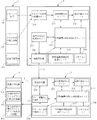
図2と図3は、本考案の第1実施形態によるシステムを示すブロック図である。本考案の第1実施形態による交通制御設備の電力線通信装置は、交通信号制御装置1と、電力線通信の符号化装置2と、電力線通信の復号化装置3と、交通信号灯器411と、交通信号の秒数カウントダウン表示装置412と、歩行者用信号機のカウントダウン表示装置413とを含む。交通信号制御1は、符号化装置2に連結される。
(First embodiment)
2 and 3 are block diagrams showing a system according to the first embodiment of the present invention. A power line communication device for a traffic control facility according to a first embodiment of the present invention includes a traffic signal control device 1, a power line
図1〜図2を参照して、交通信号制御装置1は、プロトコル信号111と、ライト出力の電力信号112と、電源供給器113と、を含む。
1 to 2, the traffic signal control device 1 includes a
符号化装置2および復号化装置3は、それぞれ回路基板に設けられて、2芯の電力線で接続する。符号化装置2および復号化装置3は、それぞれ電源供給器214、314と、CPU演算のPLC中央処理ユニット211、311と、信号変換処理ユニット217、313と、IP/ID編集識別信号処理ユニット213、317とを含む。CPU演算のPLC中央処理ユニット211で交通信号制御装置1のライト出力の電力信号112およびプロトコル信号111を処理した後、電力信号送信処理ユニット215が、プロトコル信号111およびライト出力の電力信号112を出力する方法で信号及び電源とカップリングさせる。例えば、キャリヤーのカップリングの方式で、2芯の電力線5に編集されて、電源供給器214で電源を出力して、交通信号制御装置1の電源と並列接続する。それによって、電源供給器113、214、314を復号化装置3と相互に接続する。復号化装置3は、IP/ID編集識別信号処理ユニット317と、プロトコル信号の処理ユニット316と、信号変換処理ユニット313とを含む。復号化装置3のライト駆動出力の処理ユニット315は、多芯の電力線6と交通設備4に接続される。
The
交通設備4は、交通信号灯器411(図7参照)、交通信号のカウントダウン表示装置412、歩行者用信号機のカウントダウン表示装置413及び他の関連する交通施設の表示装置(例えば、シンボル、文字、グラフィックス、青色の人形記号、多元の表示装置)であってもよい。プロトコル信号111は、RS−485またはRS−232のプロトコル信号であってもよいです。
The
符号化装置2と復号化装置3のIP/ID編集識別信号処理ユニット213、317は、信号アドレスデコードのDIPエンコーダを含む。CPU演算のPLC中央処理ユニット211、311がDIPのエンコードを識別して、誤送信の信号を防止できる。図4、図5に示すように、DIPのスイッチを使用して、エンコーディング目的を達成して、或いは、不注意でDIPのボタンが操作されることによる誤ったエンコーディングを引き起こして故障することを避ける。
The IP / ID edit identification
また、JUMPジャンパーを選んで、DIPのスイッチエンコーディングの設定機能を置き換えて、しかも振動の環境を考えて、もしJUMPジャンパーを設けるなら、ゆるみで誤ったエンコーディングによって故障を引き起こすことがある。またUSBポートを使用してJUMPジャンパーの設定機能を置き換えて、その後、数字キーボードを使用して、USBポートに接続して直接にデジタルコードを入力して設定する。 Also, if a JUMP jumper is selected to replace the DIP switch encoding setting function and the vibration environment is considered, if a JUMP jumper is provided, a loose and incorrect encoding may cause a failure. Also, the setting function of the JUMP jumper is replaced using the USB port, and then the digital keyboard is directly connected to the USB port and set using the numeric keyboard.
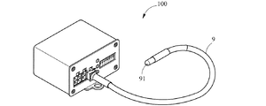
IP/ID編集識別信号処理ユニット213、317で、交差道路の間の信号を識別することによって、誤って交差道路ではない信号受けることを回避する。LEDの表示ユニット212、312のLEDの表示部は、図4に示すように、LEDランプ91を有するLEDインジケータとしてのLED指示器9とすることができる。末端のLEDランプ91は、交通信号灯器411の外側に露出させることができる。そのため、容易に外部から装置動作の状態を観察できる。復号化装置3は、図7に示すように、信号柱の交通信号灯器411に接続された時、復号化装置3のLEDの表示ユニット312を交通信号灯器411の外部に配置すせる。同様に、交通信号制御装置1に接続された符号化装置2は、図6に示すように、その末端のLEDランプ91を露出させる。それによって、技術者が、容易にLEDランプ91の明るさ、暗さ、点滅や、色で、符号化装置2と復号化装置3との関連作動が、正常かどうかが分かる。
The IP / ID editing identification
復号化装置3は、交通信号灯器411中に接続された多芯の電力線6が信号灯器の灯線となる。
In the
符号化装置2と復号化装置3は、さらに、メモリユニット218、318を含む。メモリユニット218、318は、入力および出力信号でCPU演算のPLC中央処理ユニット211、311に接続する。
The
符号化装置2、および、復号化装置3は、交通信号のカウントダウン表示装置412に接続される時、交通信号制御装置1が提供したプロトコル信号111の秒数信号を符号化装置2のプロトコル信号の処理ユニット216に出力させる。そして、CPU演算のPLC中央処理ユニット211、信号変換処理ユニット217、IP/ID編集識別信号処理ユニット213及び電力信号送信処理ユニット215で、電力伝送できる信号に変換し、しかも、交通信号制御装置1の電源供給器113に隠されて、さらに、交通信号制御装置1を介して、制御信号灯器の2芯の電力線に出力して、同時に、復号化装置3の電源供給器314と交通信号灯器411に接続される。交通信号灯器411の多芯の電力線6は、復号化装置3のCPU演算のPLC中央処理ユニット311、IP/ID編集識別信号処理ユニット317、信号変換処理ユニット313及びライト駆動出力の処理ユニット315で、信号を復元する。それによって、交通信号制御装置1が提供したプロトコル信号111の秒数信号を完全に解釈でき、交通設備4の交通信号のカウントダウン表示装置412に接続されて、正しく秒数を読み取り、専用通信回線を設ける必要がない。例えば、赤点灯のカウントダウン表示装置は、学習式を通信式に変える時、専用通信回線を設ける必要がなく、スマートグリッド通信の符号化装置を応用できて、元の多芯電力線からプロトコル信号をコンパイルする。
When the
また、交差点道路の信号は、位相で変動する時、元の3灯式の交通信号灯(青信号、黄信号、赤信号)が、5灯式の交通信号灯(左折矢印の信号、直進の矢印の信号、右折矢印の信号、黄信号、赤信号)の設備に変更するとき、本考案の実施形態によって、元の多芯の電力線からプロトコル信号をコンパイルするため、信号灯が正常に動作して、新しい線路を設ける必要がない、という特徴を有する。 In addition, when the traffic signal on the intersection road changes in phase, the original three-lamp traffic signal lamp (blue signal, yellow signal, red signal) is replaced with the five-lamp traffic signal lamp (left turn arrow signal, straight arrow signal) In order to compile the protocol signal from the original multi-core power line, according to the embodiment of the present invention, the signal light works properly when changing to the equipment of the right turn arrow signal, yellow signal, red signal), the new line It is not necessary to provide.
符号化装置2および復号化装置3の回路基板は、夏の季節によく発生する大雨と熱い太陽が照り付けることがあるため、交通信号制御装置1と交通設備4は、よく湿っぽくしかも高温の暑い環境に置かれると、更に、内部の関連電子装置の使用寿命が短くなる。そのため、スマートグリッド通信の符号化装置2とスマートグリッド通信の復号化装置3の回路基板は、「防湿コート」を使用する。回路基板にとって、良好な接着性を有るため、回路基板は、防湿、防震、防塵、防虫等と特性がある。これにより、符号化装置2および復号化装置3の故障率を低減することができる。
Since the circuit boards of the
(第2実施形態)
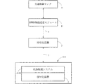
図8に示すように、に示すように、本実施形態の電力線通信装置は、一般の交通制御設備と一体に作られる。本実施形態は、交通信号制御装置1と、符号化装置2と、復号化装置3と、交通信号灯器411と、交通信号のカウントダウン表示装置412と、歩行者用信号機のカウントダウン表示装置413とを含む。交通信号制御装置1は、符号化装置2に接続される。復号化装置3は、交通信号灯器411に接続する。復号化装置3は、交通信号のカウントダウン表示装置412に接続する。復号化装置3は、歩行者用信号機のカウントダウン表示装置413に接続する。
(Second Embodiment)
As shown in FIG. 8, as shown in FIG. 8, the power line communication device of the present embodiment is made integrally with a general traffic control facility. This embodiment includes a traffic signal control device 1, an
符号化装置2は、交通信号制御装置1と一体化されている。復号化装置3は、一般の交通信号灯器411と一体化されている。復号化装置3は、一般の交通信号のカウントダウン表示装置412と一体化されている。復号化装置3は、一般の歩行者用信号機のカウントダウン表示装置413と一体化されている。
The
上述した技術手段と作動原理は、上記実施形態と同様の利点がある以外に、本実施形態による交通制御設備の電力線通信装置は、一般の交通制御設備と一体化させて、即ち、2つを1つに作らせる。それによって、一般の交通制御設備は、本実施形態による技術手段を有して、別に、一般の交通制御設備と外接する必要がなく、一般の交通制御設備の一端を本実施形態に外接する追加の作業を排除できて、より便利となる。 The technical means and operating principle described above have the same advantages as the above embodiment, but the power line communication device of the traffic control facility according to this embodiment is integrated with a general traffic control facility, that is, two Let them make one. Accordingly, the general traffic control facility has the technical means according to the present embodiment, and it is not necessary to circumscribe the general traffic control facility separately, and the general traffic control facility is added to circumscribe one end of the general traffic control facility. This makes it more convenient.
(第3実施形態)
図9〜図11は、本考案の第3実施形態のシステムを示すブロック図である。
(Third embodiment)
9 to 11 are block diagrams showing a system according to a third embodiment of the present invention.
符号化装置2および復号化装置3は、第1実施形態と同様の機能を有している。符号化装置2は、第1実施形態と同様に2芯の電力線を利用して、復号化装置3と通信信号を伝送する。復号化装置3は、また多芯の電力線6を通って、GPRS無線通信モジュール8と通信信号を伝送する。それによって、交通制御センタ7が、GPRS無線通信モジュール8を介して、道路交通監視設備414からの信号を受けて或いは信号を道路交通監視設備414に伝送させる。
The
本実施形態による道路交通監視設備414は、可変情報サインシステム4141、緊急車両支援情報通信システム(Fast Emergency Vehicle Preemption Systems)4142、および、映像監視システム4143のいずれかになる。
The road
本実施形態における符号化装置2および復号化装置3は、プロトコルコードまたはプロトコル信号を転送できる。例えば、RS−232またはRS−485等、プロトコルで信号を伝送する設備は、符号化装置2および復号化装置3を利用して信号を伝送するが、本実施形態にて説明された設備に限定されるものではない。
The
上述した詳細の説明は、本考案の好ましい実施形態のみで、本考案の範囲に限定されるものではない。本考案の効果を発揮する範囲内で同様な実施または変更は、例えば、交通管理は、電子工学技術の進歩により電力通信装置を作って信号を伝送するのが、外観か、サイズか、及び交通制御設備の一端に設けるか、または上記実施形態を交通制御設備と一体化にさせるかに関わらず、即ち、2つを1つに作らせて、交通関連の設備の技術手段を制御することに用いられるのが、本考案の範疇であるものと見なす。
上述したように、本考案の技術思想は、確かに革新であって、しかも伝統的な方法で達さない多種の効果を有しいる。。
The detailed description given above is only a preferred embodiment of the present invention and is not limited to the scope of the present invention. Similar implementations or modifications within the scope of the effect of the present invention include, for example, whether traffic management is the appearance, size, and traffic of transmitting a signal by making a power communication device due to advances in electronic technology. Regardless of whether it is provided at one end of the control facility or the embodiment described above is integrated with the traffic control facility, that is, the two are made into one to control the technical means of the traffic-related facility. It is assumed that what is used is within the scope of the present invention.
As described above, the technical idea of the present invention is certainly an innovation and has various effects that cannot be achieved by a traditional method. .
1・・・交通信号制御装置
111・・・プロトコル信号
112・・・ライト出力の電力信号
113・・・電源供給器
2・・・電力通信装置の符号化装置
211・・・CPU演算のPLC中央処理ユニット
212・・・LEDの表示ユニット
213・・・IP/ID編集識別信号処理ユニット
214・・・電源供給器
215・・・電力信号送信処理ユニット
216・・・プロトコル信号の処理ユニット
217・・・信号変換処理ユニット
218・・・メモリユニット
3・・・電力通信装置の復号化装置
311・・・CPU演算のPLC中央処理ユニット
312・・・LEDの表示ユニット
313・・・信号変換処理ユニット
314・・・電源供給器
315・・・ライト駆動出力の処理ユニット
316・・・プロトコル信号の処理ユニット
317・・・IP/ID編集識別信号処理ユニット
318・・・メモリユニット
4・・・交通設備
411・・・交通信号灯器
412・・・交通信号のカウントダウン秒数表示装置
413・・・歩行者用信号機のカウントダウン秒数表示装置
414・・・道路交通監視設備
4141・・・可変情報サインシステム
4142・・・緊急車両支援情報通信システム
(Fast Emergency Vehicle Preemption Systems)
4143・・・映像監視システム
5・・・2芯の電力線
6・・・多芯の電力線
7・・・交通制御センタ
8・・・GPRS無線通信モジュール
DESCRIPTION OF SYMBOLS 1 ... Traffic
(Fast Emergency Vehicle Preemption Systems)
4143 ...
Claims (17)
前記交通信号制御装置に接続された符号化装置と、
交通設備に接続された復号化装置と、
を含み、
前記符号化装置および前記復号化装置は、
それぞれ回路基板に設けられて、前記2芯の電力線で接続され、
それぞれプロトコル信号の処理ユニットと、電源供給器と、CPU演算のPLC中央処理ユニットと、IP/ID編集識別信号処理ユニットと信号変換処理ユニットと、を含み、
前記CPU演算のPLC中央処理ユニットでそれぞれに前記交通信号制御装置のライト出力の電力信号とプロトコル信号を処理した後、ライト出力の電力信号が、出力する方法で前記2芯の電力線に集められて、前記2芯の電力線を介して、前記符号化装置に伝送されて接続し、前記符号化装置を介して、前記交通信号制御装置に伝送され、それによって、前記交通信号制御装置が電源を出力する時、プロトコル信号のメーセッジを前記交通信号制御装置の電源にコンパイルさせて、それを電源の所に伝送することを特徴とする電力線通信装置。 It is a power line communication device that controls traffic facilities using a two-core power line as a signal from the traffic signal control device.
An encoding device connected to the traffic signal control device;
A decryption device connected to the traffic facility;
Including
The encoding device and the decoding device are:
Each provided on a circuit board, connected by the two-core power line,
Each including a protocol signal processing unit, a power supply, a CPU central processing PLC central processing unit, an IP / ID editing identification signal processing unit, and a signal conversion processing unit,
After processing the light output power signal and the protocol signal of the traffic signal control device in each of the CPU arithmetic PLC central processing unit, the light output power signal is collected on the two-core power line by the output method. , Transmitted to and connected to the encoding device via the two-core power line, and transmitted to the traffic signal control device via the encoding device, whereby the traffic signal control device outputs power A power line communication device, wherein a message of a protocol signal is compiled into a power source of the traffic signal control device and transmitted to the power source.
前記電力信号処理ユニットは、IP/ID編集識別信号処理ユニットの信号を受けたら、出力する方法で信号及び電源とカップリングさせて、前記電源供給器で電源を出力して、前記交通信号制御装置の電源と並列接続することを特徴とする請求項1に記載の電力線通信装置。 The encoding device further includes a power signal processing unit,
When the power signal processing unit receives the signal of the IP / ID editing identification signal processing unit, the power signal processing unit is coupled with a signal and a power source by an output method, and the power supply unit outputs the power source, and the traffic signal control device The power line communication device according to claim 1, wherein the power line communication device is connected in parallel with the power source of the power source.
前記メモリユニットは、入力および出力信号で前記CPU演算のPLC中央処理ユニットに接続することを特徴とする請求項1に記載の電力線通信装置。 The encoding device and the decoding device further include a memory unit,
The power line communication apparatus according to claim 1, wherein the memory unit is connected to a PLC central processing unit for the CPU operation with input and output signals.
前記復号化装置は、前記交通設備と一体化とされることを特徴とする請求項1に記載の電力線通信装置。 The encoding device is integrated with the traffic signal control device,
The power line communication device according to claim 1, wherein the decoding device is integrated with the traffic facility.
前記復号化装置は、前記交通信号灯の多芯の電力線の駆動信号灯の灯線と接続することを特徴とする請求項7に記載の電力線通信装置。 The traffic equipment is a traffic signal light, and a protocol signal is compiled from a multi-core power line of the traffic signal light,
8. The power line communication apparatus according to claim 7, wherein the decoding apparatus is connected to a driving signal lamp lamp line of a multi-core power line of the traffic signal lamp.
前記CPU演算のPLC中央処理ユニットが、DIPのエンコードを識別できて、交差点の道路の間の異なる信号源を識別することに用いられることを特徴とする請求項1に記載の電力線通信装置。 The IP / ID edit identification signal processing unit of the encoding device includes a DIP encoder for signal address decoding,
2. The power line communication device according to claim 1, wherein the PLC central processing unit of the CPU operation can identify the DIP encoding and is used to identify different signal sources between the roads at the intersection.
前記LEDの表示ユニットは、LEDインジケータを駆動し、
前記LEDインジケータは、前記交通設備と前記交通信号制御装置の外部に対応し延伸することで、LEDランプの明るさ、暗さ、点滅、および、色の少なくとも1つに基づき、前記符号化装置と前記復号化装置との関連作動が正常かどうかを判定可能であることを特徴とする請求項1に記載の電力線通信装置。 The encoding device and the decoding device further include an LED display unit,
The LED display unit drives an LED indicator;
The LED indicator extends corresponding to the traffic facility and the outside of the traffic signal control device, and based on at least one of brightness, darkness, blinking, and color of the LED lamp, The power line communication apparatus according to claim 1, wherein it is possible to determine whether or not a related operation with the decoding apparatus is normal.
前記交通信号の秒数カウントダウン表示装置は、前記符号化装置に接続され、
前記符号化装置は、前記交通信号制御装置のプロトコル信号をコンパイルして、当該信号を前記交通信号の秒数カウントダウン表示装置に伝送して表示することを特徴とする請求項1に記載の電力線通信装置。 The traffic facility is a traffic signal seconds countdown display device,
The traffic signal seconds countdown display device is connected to the encoding device;
The power line communication according to claim 1, wherein the encoding device compiles a protocol signal of the traffic signal control device, transmits the signal to a second countdown display device of the traffic signal, and displays the signal. apparatus.
前記歩行者用信号機のカウントダウン表示装置は、前記復号化装置に接続され、
前記復号化装置は、前記交通信号制御装置のプロトコル信号をコンパイルして、当該信号を前記歩行者用信号機のカウントダウン表示装置に伝送して表示することを特徴とする請求項1に記載の電力線通信装置。 The traffic facility is a pedestrian traffic light countdown display device,
The countdown display device of the pedestrian traffic light is connected to the decoding device,
The power line communication according to claim 1, wherein the decoding device compiles a protocol signal of the traffic signal control device, transmits the signal to a countdown display device of the pedestrian traffic light, and displays the signal. apparatus.
前記交通制御センタは、GPRS無線通信モジュールを介して、電力線通信装置の符号化装置と接続し、
前記符号化装置は、
回路基板に設けられて、
CPU演算のPLC中央処理ユニットと、
信号を出力することで前記CPU演算のPLC中央処理ユニットと信号変換処理ユニットとを接続するLEDの表示ユニットと、
入力信号と出力信号で前記CPU演算のPLC中央処理ユニットを接続するIP/ID編集識別信号処理ユニットと、
入力信号と出力信号で前記CPU演算のPLC中央処理ユニットを接続して及び入力信号で電力信号処理ユニットを接続する電源供給器と、
入力信号と出力信号で前記CPU演算のPLC中央処理ユニットを接続するIP/ID編集識別信号処理ユニットと、
入力信号と出力信号で前記CPU演算のPLC中央処理ユニットを接続して及び出力信号で電力信号処理ユニットを接続する電力信号処理ユニットと、
出力信号で信号変換処理ユニットを接続するプロトコル信号の処理ユニットと、
出力信号で前記CPU演算のPLC中央処理ユニットとLEDの表示ユニットとを接続する信号変換処理ユニットと、
入力信号と出力信号で前記CPU演算のPLC中央処理ユニットを接続するメモリユニットと、
を含み、
前記道路交通監視設備の信号は、電力線通信装置の復号化装置に接続されて、
前記復号化装置は、
前記符号化装置と接続され、
回路基板に設けられて、2芯の電力線で前記符号化装置と接続され、
CPU演算のPLC中央処理ユニットと、
入力信号で前記CPU演算のPLC中央処理ユニットと信号変換処理ユニットとを接続するLEDの表示ユニットと、
出力信号で前記CPU演算のPLC中央処理ユニットとLEDの表示ユニットを接続する信号変換処理ユニットと、
入力信号と出力信号で前記CPU演算のPLC中央処理ユニットを接続して及び出力信号で前記信号変換処理ユニットを接続する電源供給器と、
入力信号と出力信号で前記CPU演算のPLC中央処理ユニットを接続して及び入力信号と出力信号で前記電源供給器を接続するライト駆動出力の処理ユニットと、
入力信号で前記CPU演算のPLC中央処理ユニットを接続して及び出力信号で前記ライト駆動出力の処理ユニットを接続するプロトコル信号の処理ユニットと、
入力信号と出力信号で前記CPU演算のPLC中央処理ユニットを接続するIP/ID編集識別信号処理ユニットと、
入力信号と出力信号で前記CPU演算のPLC中央処理ユニットを接続するメモリユニットと、
を含むことを特徴とする電力線通信装置。 It is a power line communication device, and the traffic control center is used to connect signals of road traffic monitoring facilities,
The traffic control center is connected to an encoding device of a power line communication device via a GPRS wireless communication module,
The encoding device includes:
Provided on the circuit board,
PLC central processing unit for CPU operation;
An LED display unit that connects the PLC central processing unit of the CPU computation and the signal conversion processing unit by outputting a signal;
An IP / ID editing identification signal processing unit for connecting the CPU central processing PLC central processing unit with an input signal and an output signal;
A power supply unit for connecting the CPU central processing PLC unit with the input signal and the output signal and for connecting the power signal processing unit with the input signal;
An IP / ID editing identification signal processing unit for connecting the CPU central processing PLC central processing unit with an input signal and an output signal;
A power signal processing unit for connecting the PLC central processing unit of the CPU operation with an input signal and an output signal and for connecting a power signal processing unit with an output signal;
A protocol signal processing unit for connecting the signal conversion processing unit with an output signal; and
A signal conversion processing unit which connects the PLC central processing unit of the CPU computation and the LED display unit with an output signal;
A memory unit for connecting the CPU central processing unit PLC with an input signal and an output signal;
Including
The signal of the road traffic monitoring facility is connected to a decoding device of a power line communication device,
The decoding device
Connected to the encoding device;
Provided on a circuit board and connected to the encoding device by a two-core power line;
PLC central processing unit for CPU operation;
An LED display unit that connects the PLC central processing unit and the signal conversion processing unit of the CPU operation with an input signal;
A signal conversion processing unit that connects the CPU central processing PLC unit and the LED display unit with an output signal;
A power supply unit that connects the CPU central processing PLC unit with an input signal and an output signal and connects the signal conversion processing unit with an output signal;
A write drive output processing unit for connecting the CPU computing PLC central processing unit with an input signal and an output signal and for connecting the power supply unit with an input signal and an output signal;
A protocol signal processing unit that connects the CPU computing PLC central processing unit with an input signal and the write drive output processing unit with an output signal;
An IP / ID editing identification signal processing unit for connecting the CPU central processing PLC central processing unit with an input signal and an output signal;
A memory unit for connecting the CPU central processing unit PLC with an input signal and an output signal;
A power line communication apparatus comprising:
Applications Claiming Priority (2)
| Application Number | Priority Date | Filing Date | Title |
|---|---|---|---|
| TW104123621 | 2015-07-21 | ||
| TW104123621 | 2015-07-21 |
Publications (1)
| Publication Number | Publication Date |
|---|---|
| JP3206702U true JP3206702U (en) | 2016-09-29 |
Family
ID=56997785
Family Applications (1)
| Application Number | Title | Priority Date | Filing Date |
|---|---|---|---|
| JP2016003490U Expired - Fee Related JP3206702U (en) | 2015-07-21 | 2016-07-20 | Power line communication device |
Country Status (3)
| Country | Link |
|---|---|
| JP (1) | JP3206702U (en) |
| CN (1) | CN205788739U (en) |
| TW (2) | TW201705098A (en) |
Cited By (1)
| Publication number | Priority date | Publication date | Assignee | Title |
|---|---|---|---|---|
| CN115578872A (en) * | 2022-09-20 | 2023-01-06 | 扬州市法马智能设备有限公司 | A broadcast ID configuration method for communication countdown |
-
2016
- 2016-06-17 TW TW105119084A patent/TW201705098A/en unknown
- 2016-06-17 TW TW105209084U patent/TWM531631U/en not_active IP Right Cessation
- 2016-06-29 CN CN201620665618.4U patent/CN205788739U/en not_active Expired - Fee Related
- 2016-07-20 JP JP2016003490U patent/JP3206702U/en not_active Expired - Fee Related
Cited By (1)
| Publication number | Priority date | Publication date | Assignee | Title |
|---|---|---|---|---|
| CN115578872A (en) * | 2022-09-20 | 2023-01-06 | 扬州市法马智能设备有限公司 | A broadcast ID configuration method for communication countdown |
Also Published As
| Publication number | Publication date |
|---|---|
| TWM531631U (en) | 2016-11-01 |
| TW201705098A (en) | 2017-02-01 |
| CN205788739U (en) | 2016-12-07 |
Similar Documents
| Publication | Publication Date | Title |
|---|---|---|
| CN103065459B (en) | The intelligent transportation integration control platform system of sing on web geographic information system technology | |
| TW201536108A (en) | Light-emitting diode lamp, power line network system, location information writing method, projector, data processing method and conflict prevention device | |
| CN101739780A (en) | Warning light device having at least two warning lamps | |
| CN103747031A (en) | LED display screen fault network monitor system | |
| KR20140006944A (en) | A led lighting device and a led lighting network system | |
| US8928233B1 (en) | Light emitting diode control circuit with carrier signal control and package structure for the same and system for the same | |
| JP2021528025A (en) | Segmented controller | |
| US9210780B2 (en) | Street lighting system allowing multiple communication | |
| CN205644975U (en) | A system's device for optical reproduction transport information | |
| JP6077310B2 (en) | Tunnel lighting system | |
| JP2015138575A (en) | Illumination control system | |
| CN204859183U (en) | Optical coding system based on visible light communication | |
| JP4848132B2 (en) | Signal control system, signal device and program | |
| CN205788739U (en) | Intelligent power network communication technology device of traffic control equipment | |
| EP1705633A2 (en) | Light emitting device single-cluster lamp control system | |
| RU2474030C2 (en) | Method and system to control electrical equipment, in particular, lighting system | |
| CN103095487A (en) | Indication method and indication device for multiple-internet-access status | |
| CN210488542U (en) | A server front control board based on I2C bus communication | |
| Gowda et al. | Economical Acquisition of Intersection Data to Facilitate CAV Operations | |
| CN208861471U (en) | A kind of traffic signals and prompt information display system | |
| CN207363708U (en) | On professional tunnel ventilation, illumination, traffic zone band management function control machine | |
| CN112312622A (en) | Intelligent stage lighting cloud terminal control system | |
| RU2699460C1 (en) | System for duplicating traffic light signals at an adjustable pedestrian crossing | |
| JPH02141198A (en) | Electronic interlocking device | |
| JPS5937865Y2 (en) | Remote control device for device power supply |
Legal Events
| Date | Code | Title | Description |
|---|---|---|---|
| A711 | Notification of change in applicant |
Free format text: JAPANESE INTERMEDIATE CODE: A711 Effective date: 20160721 |
|
| A521 | Request for written amendment filed |
Free format text: JAPANESE INTERMEDIATE CODE: A821 Effective date: 20160721 |
|
| A521 | Request for written amendment filed |
Free format text: JAPANESE INTERMEDIATE CODE: A523 Effective date: 20160810 |
|
| R150 | Certificate of patent or registration of utility model |
Ref document number: 3206702 Country of ref document: JP Free format text: JAPANESE INTERMEDIATE CODE: R150 |
|
| R250 | Receipt of annual fees |
Free format text: JAPANESE INTERMEDIATE CODE: R250 |
|
| R250 | Receipt of annual fees |
Free format text: JAPANESE INTERMEDIATE CODE: R250 |
|
| R250 | Receipt of annual fees |
Free format text: JAPANESE INTERMEDIATE CODE: R250 |
|
| LAPS | Cancellation because of no payment of annual fees |