JP3242010U - top toy - Google Patents
top toy Download PDFInfo
- Publication number
- JP3242010U JP3242010U JP2023000903U JP2023000903U JP3242010U JP 3242010 U JP3242010 U JP 3242010U JP 2023000903 U JP2023000903 U JP 2023000903U JP 2023000903 U JP2023000903 U JP 2023000903U JP 3242010 U JP3242010 U JP 3242010U
- Authority
- JP
- Japan
- Prior art keywords
- shaft
- main body
- extending
- body portion
- top toy
- Prior art date
- Legal status (The legal status is an assumption and is not a legal conclusion. Google has not performed a legal analysis and makes no representation as to the accuracy of the status listed.)
- Active
Links
Images



Landscapes
- Toys (AREA)
Abstract

【課題】手軽に組み立てて楽しむことができるコマ玩具を提供する。
【解決手段】略平板状であり、且つ中心部に取付孔が形成される本体部10と、本体部の取付孔に挿通した状態で本体部に固定されるとともに、本体部の一面および一面の反対側である他面から突出する軸部20とを有し、軸部は、第1の方向に延在する第1延在部と、第1の方向から所定の角度をなす第2の方向に延在する第2延在部と、第1延在部と第2延在部とを繋ぐとともに第1の方向および第2の方向と略垂直の方向に延在する辺をなす屈曲部とを有する軸構成部材が複数組み合わされてなるものであり、軸部が本体部に固定されたときに、隣接する軸構成部材の第1延在部の外面又は第2延在部の外面同士が接するとともに、各軸構成部材の屈曲部が本体部の取付孔の中心部に配置され且つ屈曲部の辺の延在方向が本体部の回転軸の方向と略平行である。
【選択図】図1
A top toy that can be easily assembled and enjoyed.
A main body portion (10) having a substantially flat plate shape and having a mounting hole formed in the center thereof, a main body portion (10) inserted into the mounting hole of the main body portion and fixed to the main body portion, and one surface of the main body portion and one surface thereof. and a shank 20 projecting from the opposite surface, the shank having a first extension extending in a first direction and a second direction at an angle from the first direction. and a bent portion forming a side connecting the first and second extension portions and extending in a direction substantially perpendicular to the first direction and the second direction When the shaft is fixed to the main body, the outer surfaces of the first extending portions or the outer surfaces of the second extending portions of the adjacent shaft configuring members are aligned with each other. In addition to being in contact with each other, the bent portion of each shaft forming member is disposed at the center of the attachment hole of the main body, and the extending direction of the side of the bent portion is substantially parallel to the direction of the rotation axis of the main body.
[Selection drawing] Fig. 1
Description
本考案は、コマ玩具に関するものである。 The present invention relates to top toys.
子供の遊び用玩具の1つであるコマは、木製、金属製、プラスチック製などさまざまな素材から作られ、その形状も多様なものが知られている。そのようなコマ玩具の中でも、例えば、特許文献1に記載されるような、完成品ではなく、自ら組み立ててコマとして遊ぶものも知られている。 Tops, which are one of children's play toys, are made of various materials such as wood, metal, and plastic, and are known to have various shapes. Among such toy tops, for example, there is known a toy that is not a finished product but is assembled and played as a top, as described in
このような組み立てコマであれば、コマを回して遊ぶ楽しみだけではなく、コマを組み立てる体験をすることができ、コマ本体を白色など無地にしておくとユーザが着色したり絵を書いたりできるなど、子供の教育や学習教材としても活用することができる。 With this type of assembling top, not only can you enjoy spinning the top and playing with it, but you can also experience assembling the top. It can also be used as a child's education and learning material.
しかし、特許文献1のようなコマの場合、コマを構成する部材が多く存在するので、幼児など手や指を起用に動かすことのできない低年齢の子供では容易に組み立てることができず、保護者などに組み立てを手伝ってもらうことが必要となる。 However, in the case of the top as disclosed in
解決しようとする課題は、手軽に組み立てて楽しむことができるコマ玩具を提供することである。 The problem to be solved is to provide a top toy that can be easily assembled and enjoyed.
本考案に係る一の態様は、略平板状であり、且つ中心部に取付孔が形成される本体部と、前記本体部の取付孔に挿通した状態で前記本体部に固定されるとともに、前記本体部の一面および前記一面の反対側である他面から突出する軸部とを有し、前記軸部は、第1の方向に延在する第1延在部と、前記第1の方向から所定の角度をなす第2の方向に延在する第2延在部と、前記第1延在部と前記第2延在部とを繋ぐとともに前記第1の方向および前記第2の方向と略垂直の方向に延在する辺をなす屈曲部とを有する軸構成部材が複数組み合わされてなるものであり、前記軸部が前記本体部に固定されたときに、隣接する軸構成部材の第1延在部の外面又は第2延在部の外面同士が接するともに、各軸構成部材の前記屈曲部が前記本体部の取付孔の中心部に配置され且つ前記屈曲部の辺の延在方向が前記本体部の回転軸の方向と略平行である。 According to one aspect of the present invention, a main body portion having a substantially flat plate shape and a mounting hole formed in the center thereof; The main body has one surface and a shaft projecting from the other surface opposite to the one surface, the shaft having a first extension extending in a first direction and a a second extending portion extending in a second direction forming a predetermined angle; and bending portions forming sides extending in a vertical direction. The outer surface of the extension portion or the outer surface of the second extension portion is in contact with each other, the bent portion of each shaft constituting member is arranged at the center of the mounting hole of the main body, and the extending direction of the side of the bent portion is It is substantially parallel to the direction of the rotation axis of the main body.
本考案の構成によれば、簡単な構成でコマ玩具をつくることができるので、幼児などの低年齢の子供でも手軽に組み立てて楽しむことができる。 According to the configuration of the present invention, a top toy can be made with a simple configuration, so that even young children such as infants can enjoy assembling it easily.
以下、図面を参照して、本考案の実施の形態について説明する。以下の説明では、同一の構成において同一の符号を付して、それらの名称および機能も同じである。 BEST MODE FOR CARRYING OUT THE INVENTION Hereinafter, embodiments of the present invention will be described with reference to the drawings. In the following description, the same reference numerals are given to the same configurations, and their names and functions are also the same.
<実施の形態>
本実施の形態では、ダンボール材で構成されるコマ玩具を例に挙げて説明する。後述するが、ダンボール材製のコマ玩具は一例であり、さまざまな素材で提供することができる。<Embodiment>
In this embodiment, a top toy made of cardboard material will be described as an example. As will be described later, a top toy made of corrugated cardboard is an example, and can be provided in various materials.
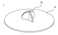
図1および図2に示すように、コマ玩具1は、本体部10と、軸部20とから構成される。 As shown in FIGS. 1 and 2, the
図1および図2に示すように、本体部10は、円形の平板状の部材で構成されており、例えば、ダンボール材から切り出して形成される。本体部10は、コマ玩具1の回転体として機能する。 As shown in FIGS. 1 and 2, the
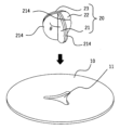
図2(a)(b)および図3に示すように、本体部10の中心部には、軸部20を挿通させるための取付孔11が形成されている。取付孔11は各辺が内側に湾曲した略三角形状に形成されており、その内縁形状が、後述する軸部20を構成する軸構成部材21,22,23の外縁形状に沿ったものとされている。 As shown in FIGS. 2(a), 2(b) and 3, a
図3に示すように、軸部20は、本体部10の取付孔11に挿通された状態で固定されている。軸部20は、コマ玩具1の回転軸として機能するとともに、コマ玩具1を手で回転させるときの持ち手として機能する。 As shown in FIG. 3 , the
図3に示すように、軸部20は、3つの軸構成部材21,22,23を組み合わせて構成されている。各軸構成部材21,22,23は、同一形状を有している。ここでは便宜上、1つの軸構成部材21の構成について説明する。 As shown in FIG. 3, the
軸構成部材21は、略円形の平板状の部材で構成されており、例えば、ダンボール材から切り出して形成される。図4に示すように、軸構成部材21は、第1延在部211と、第2延在部212と、屈曲部213とを有している。 The shaft-constituting
第1延在部211と第2延在部212とは、略半円形状を有しており、屈曲部213を介して、互いの延在方向が所定の角度θをなしている。具体的には、第1延在部211の延在方向(第1の方向)は、第2延在部212の延在方向(第2の方向)に対して所定の角度θとして約120°の角度をなしている。すなわち、本実施の形態では、軸部20が3つの軸構成部材21,22,23で構成されているので、それぞれの軸構成部材が120°の角度をなし、3つの軸構成部材で360°(1周)をなしている。 The first extending
後述するように、軸部20は、軸構成部材を複数組み合わせて構成されている。具体的には、軸部20は、軸構成部材21の第1延在部211の外面211a又は第2延在部212の外面212aを、隣接する他の軸構成部材の第1延在部の外面又は第2延在部の外面と接するように、隣接する軸構成部材同士が組み合わされて構成されている。 As will be described later, the
第1延在部211と第2延在部212のそれぞれの側端部には、凹部214が形成されている。凹部214は、軸部20が本体部10の取付孔11に挿通した状態で本体部10に係合される。 A
屈曲部213は、第1延在部211と第2延在部212とを繋ぐ屈曲する部分に相当し、第1延在部211の延在方向(第1の方向)および第2延在部212の延在方向(第2の方向)と略垂直の方向に延在する辺をなしている。 The
次に、複数の軸構成部材21,22,23を組み合わせて軸部20を構成する態様について説明する。図5に示すように、隣接する軸構成部材21,22,23の第1延在部の外面又は第2延在部の外面同士を接するようにして、一体に組み合わせる。具体的には、第1の軸構成部材21の第1延在部211の外面211aと第2の軸構成部材22の第2延在部222の外面222aを接するように合わせ、同部材21の第2延在部212の外面212aと第3の軸構成部材23の第1延在部231の外面231aを接するように合わせる。さらに、第2の軸構成部材22の第1延在部221の外面221aと第3の軸構成部材23の第2延在部231の外面231aとを接するように合わせる。 Next, a mode of configuring the
このように3つの軸構成部材21,22,23を組み合わせることで軸部20が構成される。この状態において、各軸構成部材21,22,23の屈曲部の辺212,223,233は同一の方向に延在する。また、軸部20が本体部10に固定されたときに、各軸構成部材21,22,23の屈曲部212,223,233の辺は、本体部10の取付孔11の中心部に配置され且つ屈曲部212,223,233の辺の延在方向が本体部10の回転軸の方向と略平行となる。このように構成されることで、3つの屈曲部212,223,233の辺がコマ玩具1の回転軸Cを構成する。 The
次に、コマ玩具1の組み立て方法について説明する。図3に示すように、3つの軸構成部材21,22,23を上記のとおり組み合わせてなる軸部20を、本体部10の上方から本体部10の取付孔11に挿通させる。軸部20を取付孔11に挿通させる際に、軸部20に設けられる3箇所の凹部214が取付孔11の内縁に係合され、これにより軸部20が本体部10に固定される。 Next, a method for assembling the
軸部20が本体部10に固定された状態では、回転軸Cの方向における一方側が本体部10の上面から突出し、回転軸Cの方向における他方側が本体部10の下面から突出する。本体部10の上面から突出した軸部20を構成する各軸構成部材の外面21a,22a,23aは、コマ玩具1を操作する場合の持ち手部分となる。コマ玩具1を遊ぶ際には、ユーザがこの持ち手部分(本体部10の上面から突出した軸部20)を持って回転させる。このように操作することにより、本体部10の下面から突出した軸部20が回転軸となり、コマ玩具1が回転する。 When the
<変形例>
本実施の形態に係るコマ玩具1の変形例を説明する。<Modification>
A modification of the
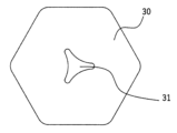
図6に、本実施の形態の第1の変形例に係るコマ玩具を構成する本体部30を表す上面図を示すである。本体部30は略六角形の外形を有しており、方向に0の中心部には取付孔31が形成されている。それ以外の構成は上記実施の形態と同じである。 FIG. 6 is a top view showing a
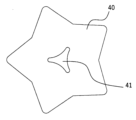
図7に、本実施の形態の第1の変形例に係るコマ玩具を構成する本体部40を表す上面図を示すである。本体部40は、略星形の外形を有しており、方向に0の中心部には取付孔41が形成されている。それ以外の構成は上記実施の形態と同じである。 FIG. 7 is a top view showing a
以上のように、本考案に係るコマ玩具によれば、ダンボール材から切り出して構成される本体部と軸部(3つの軸構成部材)とを組み合わせることによって、簡単にコマ玩具を組み立てることができる。また、コマ玩具を構成する各部材が白色など無地であれば、ユーザが部材の表面に着色したり絵を書いたりすることができる、 As described above, according to the top toy according to the present invention, the top toy can be easily assembled by combining the body portion and the shaft portion (three shaft constituting members) cut out from cardboard material. . In addition, if each member constituting the top toy is plain, such as white, the user can color or draw a picture on the surface of the member.
以上、本考案に係る実施の形態について説明したが、上記実施の形態は、その他の様々な形態で実施されることが可能であり、考案の要旨を逸脱しない範囲で種々の省略、置き換え、変更を行うことができる。 Although the embodiment according to the present invention has been described above, the above embodiment can be implemented in various other forms, and various omissions, replacements, and modifications are possible without departing from the gist of the invention. It can be performed.
例えば、上記実施の形態では、コマ玩具を構成する本体部と軸部(軸構成部材)をダンボール材から切り出して構成される部材を使用したが、これに限られるものではなく、厚手のボール紙や樹脂材、木材、金属材などさまざまな材質からなる部材を適用することができる。 For example, in the above-described embodiment, the main body and the shaft (shaft constituting member) of the top toy are cut out from a cardboard material. A member made of various materials such as resin material, wood, and metal material can be applied.
また上記実施の形態では、コマ玩具を構成する本体部の形状として円形、そしてその変形例として、略六角形、略星形の形状のものを示したが、これらに限定されるものではなく、コマ玩具として回転を担保するものであればいかなる形状のものも適用することができる。 In the above-described embodiment, the shape of the main body constituting the top toy is circular, and as modifications thereof, substantially hexagonal and substantially star-shaped. Any shape can be applied as long as it guarantees rotation as a top toy.
また上記実施の形態では、コマ玩具を構成する軸部として、3つの軸構成部材を組み合わせて構成されるものを示したが、これに限定されるものではない。軸部が4つ以上の軸構成部材から構成されるものも適用することができ、またその形状もコマ玩具として回転を担保するものであればいかなる形状のものも適用することができる。 Further, in the above-described embodiment, the shaft portion constituting the top toy is configured by combining three shaft members, but the present invention is not limited to this. A shaft composed of four or more shaft-constituting members can also be used, and any shape can be used as long as the shape of the top toy ensures rotation.
コマ玩具は、本体部と軸部とから構成され、本体部に形成される取付孔に軸部を挿通させた状態で、軸部を本体部に固定することにより、容易にコマ玩具を組み立てることができる。 The top toy is composed of a body part and a shaft part, and the top toy can be easily assembled by fixing the shaft part to the body part in a state in which the shaft part is inserted into a mounting hole formed in the body part. can be done.
1 コマ玩具
10 本体部
20 軸部
21 軸構成部材(第1の軸構成部材)
22 軸構成部材(第2の軸構成部材)
23 軸構成部材(第3の軸構成部材)
30 本体部(第1の変形例)
40 本体部(第2の変形例)
211 第1延在部
212 第2延在部
213 屈曲部
214 凹部1
22 Shaft constituent member (second shaft constituent member)
23 Shaft constituent member (third shaft constituent member)
30 main body (first modification)
40 main body (second modification)
211
Claims (4)
前記本体部の取付孔に挿通した状態で前記本体部に固定されるとともに、前記本体部の一面および前記一面の反対側である他面から突出する軸部とを有し、
前記軸部は、第1の方向に延在する第1延在部と、前記第1の方向から所定の角度をなす第2の方向に延在する第2延在部と、前記第1延在部と前記第2延在部とを繋ぐとともに前記第1の方向および前記第2の方向と略垂直の方向に延在する辺をなす屈曲部とを有する軸構成部材が複数組み合わされてなるものであり、
前記軸部が前記本体部に固定されたときに、隣接する軸構成部材の第1延在部の外面又は第2延在部の外面同士が接するともに、各軸構成部材の前記屈曲部が前記本体部の取付孔の中心部に配置され且つ前記屈曲部の辺の延在方向が前記本体部の回転軸の方向と略平行であること
を特徴とするコマ玩具。a main body having a substantially flat plate shape and having a mounting hole formed in the center thereof;
a shaft portion fixed to the main body portion while being inserted through a mounting hole of the main body portion and protruding from one surface of the main body portion and the other surface opposite to the one surface;
The shaft portion includes a first extension portion extending in a first direction, a second extension portion extending in a second direction forming a predetermined angle from the first direction, and the first extension portion. A plurality of shaft-constituting members each having a bent portion connecting the extending portion and the second extending portion and forming a side extending in a direction substantially perpendicular to the first direction and the second direction. is a
When the shaft portion is fixed to the main body portion, the outer surfaces of the first extension portions or the outer surfaces of the second extension portions of adjacent shaft constituent members are in contact with each other, and the bent portions of the respective shaft constituent members are in contact with each other. A top toy, characterized in that it is disposed at the center of a mounting hole of a main body, and the direction in which the sides of the bent portion extend is substantially parallel to the direction of the rotation axis of the main body.
Priority Applications (1)
| Application Number | Priority Date | Filing Date | Title |
|---|---|---|---|
| JP2023000903U JP3242010U (en) | 2023-03-08 | 2023-03-08 | top toy |
Applications Claiming Priority (1)
| Application Number | Priority Date | Filing Date | Title |
|---|---|---|---|
| JP2023000903U JP3242010U (en) | 2023-03-08 | 2023-03-08 | top toy |
Publications (1)
| Publication Number | Publication Date |
|---|---|
| JP3242010U true JP3242010U (en) | 2023-05-22 |
Family
ID=86395050
Family Applications (1)
| Application Number | Title | Priority Date | Filing Date |
|---|---|---|---|
| JP2023000903U Active JP3242010U (en) | 2023-03-08 | 2023-03-08 | top toy |
Country Status (1)
| Country | Link |
|---|---|
| JP (1) | JP3242010U (en) |
-
2023
- 2023-03-08 JP JP2023000903U patent/JP3242010U/en active Active
Similar Documents
| Publication | Publication Date | Title |
|---|---|---|
| JP4510051B2 (en) | Rotating magnet coupling device and assembly type toy equipped with the same | |
| US5938497A (en) | Constructional toys | |
| US5489230A (en) | Blank for constructing triangular polyhedra | |
| JP4378661B2 (en) | Assembled toy | |
| WO2006059527A1 (en) | Polyhedral toy | |
| KR200146616Y1 (en) | A game device to be possible throwing and building | |
| US6439945B1 (en) | Octopus-shaped built-up toy | |
| EP1291051A2 (en) | Three-dimensional toy built up with freely connectable parts | |
| US11433317B1 (en) | Building toy set | |
| US6419542B1 (en) | Three-dimensional toy built up with freely connectable parts | |
| JP3196890U (en) | Assembly toys | |
| CN112272582B (en) | Cube element for construction type toy | |
| KR200495487Y1 (en) | block for A play | |
| JP2017200573A (en) | Assembled model toys and their parts | |
| JP7536167B1 (en) | toy | |
| JP7315269B1 (en) | block toy | |
| JP3197374U (en) | Assembly toys | |
| JP3869701B2 (en) | Assembly block | |
| KR100846916B1 (en) | Assembly toy playing house | |
| JP6205540B1 (en) | Freshly assembled toys | |
| JP2006230989A (en) | Assembly toy | |
| KR200376218Y1 (en) | Goods having the multi-amusement | |
| KR200380938Y1 (en) | A solid panel of toy | |
| CN2283501Y (en) | modular doll | |
| KR200316114Y1 (en) | Recombinable toy-top and a Plate carved parts of toy-top |
Legal Events
| Date | Code | Title | Description |
|---|---|---|---|
| R150 | Certificate of patent or registration of utility model |
Ref document number: 3242010 Country of ref document: JP Free format text: JAPANESE INTERMEDIATE CODE: R150 |