【0001】
【発明の属する技術分野】
本発明は、例えば道路トンネル内部の光透過率または吸光係数を光学的に測定する煙霧透過率測定装置に関するものである。
【0002】
【従来の技術】
従来、この種の煙霧透過率測定装置は、投光部と受光部を100m程度離して設け、投光部から煤煙・煤塵などが浮遊する煙霧中に光を透過させて、その透過率を測定していた。
【0003】
そして、従来例では、投光部の光源の光束減衰、受光部素子の経年劣化およびレンズ面の汚れなどによる測定値の低下を補償するために、校正機能が備えられ、一定周期毎に校正を行い、低下分の補償を行っていた。また光透過率の絶対値(100%)の設定は、測定現地にて目視により合わせるか、設定値の記録より、その最高値を合わせるようにしていた。
【0004】
【発明が解決しようとする課題】
しかし、上記の従来技術では下記のような問題があった。
(1)一定周期毎に数%ずつゲインを調整するため、精度的に数%の誤差は避けられない。
(2)絶対値(100%)の設定が目視により合わせられるため、誤差が大きくなるおそれがあった。
(3)投光部と受光部の間が100m離れているため、光軸合わせ、ゲイン調整などの現場調整に時間を要した。
(4)測定処理部のノイズおよび温度による光透過率の変動(温度ドリフト)によって測定精度が悪くなっていた。
(5)投光部、受光部間でのトンネル側面内装板の反射光の影響により不安定になることがあった。
【0005】
このため、本発明は、調整が容易で測定精度が良い煙霧透過率測定装置を提供することを目的とする。
【0006】
【課題を解決するための手段】
上記の目的を達成するため、本発明の煙霧透過率測定装置は、光の投射と受光を行なう投受光部と、前記投受光部からの光を前記投受光部に反射する反射部と、前記反射部と前記投受光部とを対向させ一体的に設ける測定筒と、前記測定筒内外に空気を流通させる絶対値校正手段とを備え、前記投受光部で、通常測定時と絶対値測定時において空気中を透過する光の強さを測定してトンネル内の光透過率を求める煙霧透過率測定装置であって、前記絶対値校正手段は、トンネル内の空気を前記測定筒内に取入れる空気経路に設けた入口電磁弁と、前記測定筒内の空気をトンネル内へ排出する空気経路に前記測定筒側から順に設けた吸引ポンプおよび出口電磁弁と、前記入口電磁弁と前記測定筒間および前記吸引ポンプと前記出口電磁弁間とを結ぶ空気経路に設けた校正電磁弁および空気清浄装置とを備え、通常測定時は、前記入口電磁弁と出口電磁弁とを開、前記校正電磁弁を閉とし、絶対値測定時は、前記入口電磁弁と出口電磁弁とを閉、前記校正電磁弁を開とし、通常測定時および絶対値測定時で別々の流通経路を設け、前記吸引ポンプを共用して用いるものである。
【0011】
【発明の実施の形態】
本発明の構成は、投受光部の光源から発せられた光が反射部で反射されて投受光部に入射し、光電変換部で電気信号(電圧)に変換された後に演算処理部に入り、ここで光透過率または吸光係数が演算されるという作用を有する。
【0012】
また、本発明は、演算処理部が、通常測定および絶対値校正の各測定値と、測定光(校正光)を遮断したときの測定値(0%校正)を用いて誤差のない光透過率または吸光係数を演算することができ、測定値のノイズや温度ドリフトなどを除去することができる作用を有する。
【0013】
さらに、本発明は、絶対値校正手段が、トンネル内の汚れた空気を空気清浄装置で清浄にし測定筒内に満たし、このときの校正光を測定することによって光透過率の絶対値(100%)を演算することができる作用を有する。
【0014】
以下、本発明の実施の形態を図1ないし図6に沿って説明する。
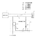
本実施の形態の煙霧透過率測定装置は、図1に示すように、投受光部1と、反射部2とを相対向させて設けるとともに、投受光部1から投射された光により、測定筒3内の反射部2との間に浮遊する煤塵や煤煙などの煙霧粒子層4の透過率または吸光係数を測定するものである。また、測定筒3内を100%の清浄な空気で満たすための絶対値校正手段5を有し、演算処理部6を有した構成である。そして、図2は投受光部1の構成を示すもので、防塵筒ケーシング7、開口7a,7b、光源8、第一対物レンズ9、光学窓用ガラス10、第二対物レンズ11、視野限定用アパーチャ12、拡散板13、光電変換部14、光源点滅回路15、プリアンプ回路16を有するものである。同図2において、投受光部1と反射部2とを相対向させて、しかも測定筒3を介して一体的に設置してあり、投受光部1から投光された光、すなわち測定光aにより、投受光部1と反射部2との間に浮遊する煤煙、煤塵などの煙霧粒子層4の光透過率または吸光係数を演算する。
【0015】
具体的には、投受光部1の防塵筒ケーシング7に、図3の反射部2のプリズム17に対応する位置に光出射用または光入射用開口7a,7bが形成され、光出射用開口7aに対応して第1対物レンズ9が配置されている。また光出射用開口7bに対応する位置には、反射部2からの測定光aが第2対物レンズ11、視野限定用アパーチャー12、拡散板13を介して入射されて、光電気変換をする光電変換部14と、この光電変換部14からの出力電気信号を増幅するプリアンプ回路16が設けられている。
【0016】
図4は自動絶対値構成手段を示すもので、通常測定時はトンネル内の汚れた空気を測定筒3内に入れてVI(Visibility)値測定を行う。絶対値校正時は、測定筒3内をフィルタ18や電気集塵機等の空気清浄装置19により清浄にした空気で満たし、この時のVI値を100%として絶対値校正を行う。つぎに、図4,図5に沿って、絶対値校正手段の動作を説明する。通常測定時は、入口電磁弁20、出口電磁弁21を開にし、校正電磁弁22を閉にすることによって吸引ポンプ23によりトンネル内の汚れた空気を測定筒3内に吸引し測定を行う。絶対値測定時は、校正電磁弁22を開にし、入口電磁弁20と出口電磁弁21を閉にすることによって吸引ポンプ23と空気清浄装置19によって、測定筒3内の空気を清浄にし絶対値校正に使用する。
【0017】
図6はプリアンプ回路16からの電気信号(電圧)VA,VAOの波形を示したものである。そして、前記演算処理部6では、この電気信号(電圧)VA,VAOに基づいて光透過率または吸光係数が演算される。
【0018】
すなわち、一般に煙霧粒子層4などの光透過率TLは次の(1)式で表せる。
【0019】
【数5】
【0020】
しかし上記電気信号(電圧)の値VA,VAOはノイズ、温度ドリフトが入っているため、これらを除去する必要がある。このため、測定光aを遮断したとき(0%校正)の電気信号(電圧)の値VCを使って、VA−VC,VAO−VCを用い、誤差のない光透過率TL1はつぎの(2)式で求める。
【0021】
【数6】
【0022】
また、吸光係数Kはつぎの(3)式で表される。
K=(1/2L)・log(1/TL) ・・・・(3)
ただし、L:投受光部1と反射部2との間の距離。
【0023】
つぎに光透過率または吸光係数の具体的な測定方法を説明する。
光源点滅回路15によって断続光となった光源8の光の一部は、測定光aとして第1対物レンズ9を介して反射部2に投射される。反射部2のプリズム17で反射された測定光aは第2対物レンズ11などを介して光電変換部14へ入り、電気信号(電圧)としてプリアンプ回路部16を経て処理部6に入力される。
【0024】
また、一定周期毎に自動的に絶対値校正が行われ、この時の測定光aも電気信号(電圧)に変換された後、処理部6に入力される。ここで上記(1)ないし(3)式に基づいて光透過率または吸光係数が演算されて、所定の箇所に出力表示(図示せず)される。
【0025】
このように本実施の形態の煙霧透過率測定装置によれば、自動的に絶対値校正手段5により100%の絶対値校正を行うことができる。また、演算処理部6によって光透過率および吸光係数を演算することによって光学窓用ガラスの汚れによる光透過率の低下および温度による光透過率の変動(温度ドリフト)を補正することができるので測定精度の向上を図ることができる。
【0026】
【発明の効果】
以上のように、本発明の構成によれば、投受光部と反射部とが測定筒を介して一体的に設けられているため、光軸合わせなどの現場調整を行う必要がない効果を有する。
【0027】
また、本発明の構成によれば、光透過率および吸光係数の演算をする際に、投受光部形の汚れによる光透過率の低下や温度による透過率を補正することができるので、測定精度の向上を図ることができる効果を有する。
【0028】
さらに、本発明の構成によれば、光透過率の絶対値(100%)を、測定筒内の汚い空気と清浄空気と置換して測定するため、従来の目視による場合と異なり、誤差をほとんどなくすことができる効果を有する。
【図面の簡単な説明】
【図1】本発明の実施の形態における煙霧透過率測定装置の概略構成図
【図2】投受光部の概略構成図
【図3】反射部の概略構成図
【図4】絶対値校正手段の概略構成図
【図5】絶対値校正手段の各電磁弁と吸引ポンプの動作タイミングチャート
【図6】光電変換部の電気信号を増幅して得られる電気信号波形図
【符号の説明】
1 投受光部
2 反射部
3 測定筒
4 煙霧粒子層
5 絶対値構成手段
6 演算処理部
14 光電変換部
a 測定光
19 空気清浄装置
20 入口電磁弁
21 出口電磁弁
22 構成電磁弁
23 吸引ポンプ[0001]
TECHNICAL FIELD OF THE INVENTION
The present invention relates to a fume transmittance measuring device that optically measures, for example, light transmittance or extinction coefficient inside a road tunnel.
[0002]
[Prior art]
Conventionally, this type of fume transmittance measurement device measures the transmittance by providing a light emitting part and a light receiving part at a distance of about 100 m, and transmitting light from the light emitting part into fumes in which soot and dust float. Was.
[0003]
In the conventional example, a calibration function is provided in order to compensate for a decrease in measured values due to attenuated luminous flux of the light source of the light emitting unit, aging of the light receiving unit element, and contamination of the lens surface. And compensated for the decrease. The setting of the absolute value (100%) of the light transmittance was visually adjusted at the measurement site, or the highest value was adjusted by recording the set value.
[0004]
[Problems to be solved by the invention]
However, the above prior art has the following problems.
(1) Since the gain is adjusted by several percents at regular intervals, an error of several percents is unavoidable in accuracy.
(2) Since the setting of the absolute value (100%) is visually adjusted, the error may be increased.
(3) Since the distance between the light projecting unit and the light receiving unit is 100 m, it takes time to perform on-site adjustment such as optical axis alignment and gain adjustment.
(4) The measurement accuracy deteriorated due to the fluctuation of the light transmittance (temperature drift) due to noise and temperature in the measurement processing unit.
(5) There is a case where the light becomes unstable due to the influence of the reflected light of the inner side plate of the tunnel between the light emitting part and the light receiving part.
[0005]
For this reason, an object of the present invention is to provide a fume transmittance measuring device that is easy to adjust and has good measurement accuracy.
[0006]
[Means for Solving the Problems]
In order to achieve the above object, the fume transmittance measuring device of the present invention is a light emitting and receiving unit for projecting and receiving light, a reflecting unit for reflecting light from the light emitting and receiving unit to the light emitting and receiving unit, A measuring tube provided integrally with the reflecting unit and the light emitting and receiving unit facing each other, and an absolute value calibrating unit for flowing air into and out of the measuring tube, wherein the light emitting and receiving unit performs normal measurement and absolute value measurement. A fume transmittance measuring device for measuring the intensity of light passing through the air to determine the light transmittance in the tunnel, wherein the absolute value calibrating means takes the air in the tunnel into the measuring cylinder An inlet solenoid valve provided in an air path, a suction pump and an outlet solenoid valve provided in order from the measurement cylinder side in an air path for discharging air in the measurement cylinder into the tunnel, and between the inlet solenoid valve and the measurement cylinder. And between the suction pump and the outlet solenoid valve. A calibration electromagnetic valve and an air purifying device provided in the air passage, and during normal measurement, the inlet electromagnetic valve and the outlet electromagnetic valve are opened, and the calibration electromagnetic valve is closed. The solenoid valve and the outlet solenoid valve are closed, the calibration solenoid valve is opened, separate flow paths are provided for normal measurement and absolute value measurement, and the suction pump is used in common.
[0011]
BEST MODE FOR CARRYING OUT THE INVENTION
According to the configuration of the present invention, light emitted from the light source of the light emitting and receiving unit is reflected by the reflecting unit, enters the light emitting and receiving unit, is converted into an electric signal (voltage) by the photoelectric conversion unit, and then enters the arithmetic processing unit. Here, the light transmittance or the extinction coefficient is calculated.
[0012]
Further, the present invention provides an arithmetic processing unit that uses each measurement value of normal measurement and absolute value calibration, and a measurement value (0% calibration) obtained when the measurement light (calibration light) is cut off, to use a light transmittance without error. Alternatively, it has the effect of calculating the extinction coefficient and removing noise or temperature drift of the measured value.
[0013]
Further, according to the present invention , the absolute value calibrating means cleans dirty air in the tunnel with an air purifying device and fills the inside of the measuring cylinder, and measures the calibration light at this time to thereby determine the absolute value of the light transmittance (100%). ) Can be calculated.
[0014]
Hereinafter, an embodiment of the present invention will be described with reference to FIGS.
As shown in FIG. 1, the haze transmittance measuring apparatus of the present embodiment is provided with a light emitting and receiving unit 1 and a reflecting unit 2 facing each other, and a measuring tube is provided by light projected from the light emitting and receiving unit 1. The transmissivity or the extinction coefficient of the fume particle layer 4 such as dust and soot floating between the reflecting portion 2 and the reflection portion 2 is measured. Further, it has an absolute value calibrating means 5 for filling the inside of the measuring cylinder 3 with 100% clean air, and has an arithmetic processing unit 6. FIG. 2 shows the configuration of the light emitting and receiving unit 1, and includes a dustproof casing 7, openings 7a and 7b, a light source 8, a first objective lens 9, an optical window glass 10, a second objective lens 11, and a field of view limiting. It has an aperture 12, a diffusion plate 13, a photoelectric conversion unit 14, a light source blinking circuit 15, and a preamplifier circuit 16. In FIG. 2, the light projecting / receiving section 1 and the reflecting section 2 are opposed to each other and are integrally installed via a measuring tube 3, and the light projected from the projecting / receiving section 1, that is, the measuring light a Thus, the light transmittance or extinction coefficient of the fume particle layer 4 of soot and dust floating between the light emitting and receiving unit 1 and the reflecting unit 2 is calculated .
[0015]
More specifically, light emission or light entrance openings 7a and 7b are formed in the dustproof casing 7 of the light emitting and receiving unit 1 at positions corresponding to the prisms 17 of the reflection unit 2 in FIG. The first objective lens 9 is arranged corresponding to. In addition, at a position corresponding to the light exit aperture 7b, the measurement light a from the reflection unit 2 is incident via the second objective lens 11, the aperture 12 for limiting the field of view, and the diffusion plate 13 to perform photoelectric conversion. A conversion unit 14 and a preamplifier circuit 16 for amplifying an output electric signal from the photoelectric conversion unit 14 are provided.
[0016]
FIG. 4 shows an automatic absolute value constructing means. At the time of normal measurement, dirty air in the tunnel is put into the measuring cylinder 3 to measure VI (Visibility) value. At the time of absolute value calibration, the inside of the measuring cylinder 3 is filled with air cleaned by an air cleaning device 19 such as a filter 18 or an electric dust collector, and the absolute value calibration is performed with the VI value at this time set to 100%. Next, the operation of the absolute value calibration means will be described with reference to FIGS. At the time of normal measurement, the inlet solenoid valve 20 and the outlet solenoid valve 21 are opened, and the calibration solenoid valve 22 is closed, so that the suction pump 23 sucks dirty air in the tunnel into the measurement cylinder 3 and performs measurement. At the time of measuring the absolute value, the calibration solenoid valve 22 is opened and the inlet solenoid valve 20 and the outlet solenoid valve 21 are closed to clean the air in the measuring cylinder 3 by the suction pump 23 and the air cleaning device 19, and the absolute value is measured. Used for calibration.
[0017]
FIG. 6 shows waveforms of electric signals (voltages) V A and V AO from the preamplifier circuit 16. Then, the arithmetic processing unit 6 calculates the light transmittance or the extinction coefficient based on the electric signals (voltages) V A and V AO .
[0018]
That is, generally, the light transmittance TL of the fog particle layer 4 and the like can be expressed by the following equation (1).
[0019]
(Equation 5)
[0020]
However, since the values VA and VAO of the electric signals (voltages) include noise and temperature drift, it is necessary to remove them. Thus, using the value V C of the electric signal obtained when cutting off the measuring light a (0% Calibration) (voltage), V A -V C, using a V AO -V C, no error light transmittance TL1 Is obtained by the following equation (2).
[0021]
(Equation 6)
[0022]
The extinction coefficient K is expressed by the following equation (3).
K = (1 / 2L) .log (1 / T L ) (3)
Here, L is the distance between the light emitting / receiving unit 1 and the reflecting unit 2.
[0023]
Next, a specific method for measuring the light transmittance or the extinction coefficient will be described.
A part of the light of the light source 8 which has become the intermittent light by the light source blinking circuit 15 is projected to the reflection unit 2 via the first objective lens 9 as the measurement light a. The measurement light a reflected by the prism 17 of the reflection unit 2 enters the photoelectric conversion unit 14 via the second objective lens 11 and the like, and is input to the processing unit 6 via the preamplifier circuit unit 16 as an electric signal (voltage).
[0024]
Further, absolute value calibration is automatically performed at regular intervals, and the measuring light a at this time is also converted into an electric signal (voltage) and then input to the processing unit 6. Here, the light transmittance or the extinction coefficient is calculated based on the above equations (1) to (3), and is output and displayed (not shown) at a predetermined location.
[0025]
As described above, according to the haze transmittance measuring apparatus of the present embodiment, the absolute value calibration means 5 can automatically perform 100% absolute value calibration. Further, since the light transmittance and the extinction coefficient are calculated by the arithmetic processing unit 6, a decrease in light transmittance due to contamination of the optical window glass and a change (temperature drift) in light transmittance due to temperature can be corrected. Accuracy can be improved.
[0026]
【The invention's effect】
As described above, according to the configuration of the present invention, since the light emitting and receiving unit and the reflecting unit are integrally provided via the measurement tube, there is an effect that it is not necessary to perform on-site adjustment such as optical axis alignment. .
[0027]
Further, according to the configuration of the present invention , when calculating the light transmittance and the extinction coefficient, it is possible to correct the decrease in the light transmittance due to the contamination of the light emitting and receiving unit and the transmittance due to the temperature, so that the measurement accuracy is improved. This has the effect of being able to achieve an improvement.
[0028]
Further, according to the configuration of the present invention , since the absolute value (100%) of the light transmittance is measured by replacing the dirty air and the clean air in the measuring cylinder with each other, the error is almost completely different from the conventional visual observation. It has an effect that can be eliminated.
[Brief description of the drawings]
[1] a schematic configuration diagram 2 is a schematic configuration diagram of a light emitting and receiving unit 3 is a schematic diagram of the reflective portion 4 shows the absolute value calibration means fume transmittance measuring apparatus according to an embodiment of the present invention Schematic configuration diagram [FIG. 5] Operation timing chart of each solenoid valve and suction pump of absolute value calibration means [FIG. 6] Electric signal waveform diagram obtained by amplifying electric signal of photoelectric conversion unit [Description of reference numerals]
DESCRIPTION OF SYMBOLS 1 Emitter / receiver 2 Reflector 3 Measuring cylinder 4 Smoke particle layer 5 Absolute value constructing means 6 Arithmetic processing unit 14 Photoelectric converter a Measurement light 19 Air purifier 20 Inlet solenoid valve 21 Outlet solenoid valve 22 Component solenoid valve 23 Suction pump