JP3550108B2 - Roof structure of building and method of building the same - Google Patents
Roof structure of building and method of building the same Download PDFInfo
- Publication number
- JP3550108B2 JP3550108B2 JP2001171227A JP2001171227A JP3550108B2 JP 3550108 B2 JP3550108 B2 JP 3550108B2 JP 2001171227 A JP2001171227 A JP 2001171227A JP 2001171227 A JP2001171227 A JP 2001171227A JP 3550108 B2 JP3550108 B2 JP 3550108B2
- Authority
- JP
- Japan
- Prior art keywords
- rafter
- purlin
- roof
- roof structure
- fixed
- Prior art date
- Legal status (The legal status is an assumption and is not a legal conclusion. Google has not performed a legal analysis and makes no representation as to the accuracy of the status listed.)
- Expired - Fee Related
Links
- 238000000034 method Methods 0.000 title claims description 34
- 238000005304 joining Methods 0.000 claims description 19
- 238000010276 construction Methods 0.000 description 14
- 239000000463 material Substances 0.000 description 11
- 229910000831 Steel Inorganic materials 0.000 description 10
- 239000011120 plywood Substances 0.000 description 10
- 239000010959 steel Substances 0.000 description 10
- 230000009194 climbing Effects 0.000 description 3
- 238000007796 conventional method Methods 0.000 description 3
- 230000000694 effects Effects 0.000 description 3
- 239000002023 wood Substances 0.000 description 2
- 241000218645 Cedrus Species 0.000 description 1
- 239000010426 asphalt Substances 0.000 description 1
- 230000015572 biosynthetic process Effects 0.000 description 1
- 238000009432 framing Methods 0.000 description 1
- 239000003292 glue Substances 0.000 description 1
- 238000004519 manufacturing process Methods 0.000 description 1
- 239000002184 metal Substances 0.000 description 1
- 238000002360 preparation method Methods 0.000 description 1
Images




Landscapes
- Rod-Shaped Construction Members (AREA)
Description
【0001】
【発明の属する技術分野】
本発明は、湾曲した屋根形状を有する建造物の屋根構造体およびその建造方法に関する。
【0002】
【従来の技術】
図15は、従来の技術の建造物1の構成を妻側から見て示す断面図である。たとえば家屋などの建造物1は、基礎工事を経て、基礎部分2に土台3が敷設される。建造物1は、土台3から上方に延びる通し柱4および管柱が立設され、胴差しが管柱の上端部に取り付けられ、梁5が柱間を架橋される。建造物1は、2階用の根太が梁5および胴差しに架設されて、2階用の根太に2階用の床板が張られる。
【0003】
また建造物1は、小屋組構造を有する。建造物1は、小屋ばり5aが通し柱4の上端部間にほぼ水平に架橋される。小屋ばり5aには、小屋ばり5aから上方に延びる小屋つか6が、間隔をあけて複数固定される。複数の小屋つか6は、長さが多段的に変化されて設けられる。
【0004】
建造物1は、複数の母屋7が各小屋つか6の上端部に固定され、各母屋7の上端部間にわたって垂木8が架設される。母屋間に架設される垂木8は、直線的に傾斜して延びて配置される。垂木8の上部には野地板が貼り付けられ、野地板の上部に瓦などの屋根葺材料が取り付けられる。
【0005】
このような従来の構成を有する屋根構造体は、切妻屋根または寄棟屋根などの直線的に延びる垂木8によって屋根形状が決定する。建造物1の屋根形状の傾斜は、垂木8の傾斜する角度によって決定される。このような垂木8を母屋7に架設する屋根構造体は、垂木8がほぼ直線的に延びるので、湾曲した屋根形状に形成することが難しく、建造することができる屋根形状が制限されてしまう。したがって多様な屋根形状を形成することができず、居住者が望む屋根形状を形成することができないという問題がある。
【0006】
図16は、他の従来の技術の屋根構造体20の一部を示し、妻側から見た断面図である。屋根構造体20は、湾曲した湾曲部22を有する構造用合板21を含んで構成される。湾曲部22は、建造される屋根構造体の屋根形状とほぼ同一形状の形状を有する。構造用合板21は、柱16間に嵌め込まれて、棟木24と軒けた25とによって固定される。湾曲部22は、屋根構造体20の外方に向かっ湾曲形状を有する。
【0007】
母屋17は、構造用合板21の湾曲部22に取り付けられ、母屋17の上端部に野地板23が取り付けられる。このように垂木の代用として湾曲部22を有する構造用合板21を用いることによって、屋根構造体20は、湾曲した屋根形状を形成する。
【0008】
図17は、さらに他の従来の技術の屋根構造体30の一部を示し、妻側から見た断面図である。屋根構造体30は、屋根形状に応じて湾曲した梁集成材31を有する。梁集成材31は、湾曲した板状に形成される。梁集成材31は、小屋ばり35aから上方に延びる複数のトラス部材32によって支持され、小屋ばり35の上端部に固定される。このように任意の形状に湾曲させた梁集成材31を、トラス部材32によって支持することによって、屋根構造体30は、湾曲した屋根形状を形成する。
【0009】
図18は、さらに他の従来の技術の屋根構造体40の一部を示し、妻側から見た断面図である。屋根構造体40は、柱46の上端部間にアーチ状に湾曲させたH型鋼41が架橋される。H型鋼41は、屋根形状に応じて形成される。また母屋47がH型鋼41に固定され、母屋47の上端部に野地板43が取り付けられる。このようにアーチ状に柱間を架橋するH型鋼41を用いることによって、屋根構造体40は、湾曲した屋根形状を形成する。
【0010】
【発明が解決しようとする課題】
図16に示す従来の技術の屋根構造体20では、湾曲した屋根形状に応じて構造用合板21を加工する必要がある。したがって屋根形状が異なった場合は、新たに構造用合板21を製作しなければならず、構造用合板21は、その生産コストが高くなる。したがって構造用合板21が用いられる屋根構造体20は、建造に費やされる費用が増加するという問題がある。
【0011】
図17に示す従来の技術の屋根構造体30では、図16に示す屋根構造体30と同様に、梁集成材31を屋根形状に応じて加工する必要があるので、建造に費やされる費用が増加するという問題がある。
【0012】
図18に示す従来の技術の屋根構造体40でも、図16および図17に示す屋根構造体20,30と同様にH型鋼41を屋根形状に応じてアーチ状に加工するので、建造に費やされる費用が増加するという問題がある。さらに鉄骨梁を用いた建造物は、通常の大工工事では建造することができない。したがってH型鋼41を屋根構造体に用いる場合、大工工事以外の別業種者によって施工されるので、よりコスト高になるとともに納期がかかるという問題がある。また図16〜図18に示す従来の屋根構造体20,30,40では、従来よく行われている切妻屋根の小屋組構造とは異なり、小屋組構造を工夫する必要があり、屋根形状が直線的である場合に比べて手間がかかるという問題がある。
【0013】
したがって本発明の目的は、湾曲した屋根形状を、容易かつ安価に建造することができる建造物の屋根構造体およびその建造方法を提供することである。
【0017】
【課題を解決するための手段】
本発明は、上端部の高さ位置が、屋根形状に応じて多段に異ならせて配置される複数の母屋と、
各母屋の上端部間にわたって張架される垂木と、
垂木を各母屋の上端部に固定する固定部材とを含み、
垂木は、弾発的に湾曲された状態で、固定部材によって母屋に固定され、
前記垂木は、はり間方向に延び、複数の母屋の上端部間にわたって張架される複数の垂木部材によって構成され、相互に隣接する2つの垂木部材のうち、上方側に配置される垂木部材の下端部には、垂木部材厚み方向に傾斜する第1接合面が形成され、
前記隣接する2つの垂木部材のうち、下方側に配置される垂木部材の上端部には、垂木部材厚み方向に傾斜する第2接合面が形成され、
前記上方側に配置される垂木部材の下端部と前記下方側に配置される垂木部材の上端部とは、第1接合面上に第2接合面を重ねた状態で当接されて継ぎ手部分を構成し、この継ぎ手部分が、前記固定部材によって母屋に固定されることを特徴とするの建造物の屋根構造体である。
【0018】
本発明に従えば、垂木が弾発的に湾曲された状態で、固定部材によって母屋に固定される。したがって垂木は、弾発的に変形することによって、屋根形状に応じた形状になるので、湾曲した屋根形状であっても、各屋根形状に応じて垂木の形状を加工する必要がない。すなわち弾発性を有する垂木を、上端部の高さが多段的に異なって配置される母屋に固定することによって、任意の屋根形状を有する屋根構造体を容易に形成することができる。またこのように屋根形状に応じて垂木の形状を加工する必要がないので、垂木として用いられる垂木部材を、屋根形状にかかわらず共通化することができる。
【0019】
また母屋の高さ位置および母屋間の間隔を、屋根形状に応じて適切に調整して、垂木を母屋に固定することによって、所定の湾曲した屋根形状に垂木を容易に変形させることができる。また建造物の建造現場で、母屋の高さ位置を微調整することによって、寸法誤差および取付誤差を修正し、正確な屋根形状を有する屋根構造体を形成することができる。
また複数の垂木部材によって垂木が構成され、上方側に配置される垂木部材の第1接合面と下方側に配置される垂木部材の第2接合面とが重なって継ぎ手部分を形成する。この継ぎ手部分が固定部材によって母屋に固定される。また固定部材は、垂木を厚み方向に挿通して、垂木を母屋に結合する。したがって固定部材は、厚み方向に垂木を挿通することによって、継ぎ手部分では、一方の垂木部材と他方の垂木部材とを挿通して、互いの垂木部材を連結することができる。
さらに継ぎ手部分を母屋上で固定することによって、継ぎ手部分上方から荷重が加えられた場合、継ぎ手部分が母屋に固定されるので、継ぎ手部分が下方に変形することを防止することができる。これによって接合部分である継ぎ手部分の変形を防ぎ、継ぎ手部分の強度を向上させることができる。
【0020】
また本発明は、ほぼ垂直に延びる柱に固定され、ほぼ水平に延びる小屋ばりと、
小屋ばりからほぼ垂直かつ上方に延び、小屋ばりに間隔をあけて固定される複数の小屋つかと、
けた行方向に延び、各小屋つかの上端部に固定される複数の母屋と、
各母屋の上端部間にわたって張架される垂木と、
垂木を各母屋の上端部に固定する固定部材とを含み、
複数の小屋つかの上端部は、その高さ位置が屋根形状に応じて多段的に変化し、垂木は弾発的に湾曲された状態で、固定部材によって各母屋に固定され、
前記垂木は、はり間方向に延び、複数の母屋の上端部間にわたって張架される複数の垂木部材によって構成され、相互に隣接する2つの垂木部材のうち、上方側に配置される垂木部材の下端部には、垂木部材厚み方向に傾斜する第1接合面が形成され、
前記隣接する2つの垂木部材のうち、下方側に配置される垂木部材の上端部には、垂木部材厚み方向に傾斜する第2接合面が形成され、
前記上方側に配置される垂木部材の下端部と前記下方側に配置される垂木部材の上端部とは、第1接合面上に第2接合面を重ねた状態で当接されて継ぎ手部分を構成し、この継ぎ手部分が、前記固定部材によって母屋に固定されることを特徴とするの建造物の屋根構造体である。
【0021】
本発明に従えば、小屋つかの高さ位置は、小屋つかの長さを変化することによって、容易に調整することができる。したがって複数の小屋つかの高さ位置を多段に異ならせて設けることによって、小屋つかごとに固定される母屋の高さ位置を多段に設けることができる。このように高さ位置が多段的に設けられた母屋間を、垂木が弾発的に湾曲されて、張架されることによって、湾曲した屋根形状を有する屋根構造体を形成することができる。
またこのような構成は、切妻屋根または寄棟屋根などの湾曲しない屋根形状を有する屋根構造体と類似している。したがって湾曲しない屋根構造体とほぼ同様の小屋組構造によって建造を行うことができる。すなわち従来の小屋組構造とほぼ同様の建造工程において、小屋つかの長さおよびピッチを、任意の屋根形状に応じて、調整するだけで垂木の湾曲具合を整えることができ、湾曲した屋根形状を有する屋根構造体を容易に形成することができる。
また複数の垂木部材によって垂木が構成され、2つの垂木部材の各接合面とが重なって継ぎ手部分を形成する。この継ぎ手部分が固定部材によって母屋に固定される。固定部材は、垂木を厚み方向に挿通して、垂木を母屋に結合する。したがって固定部材は、継ぎ手部分において、一方の垂木部材と他方の垂木部材とを挿通して、互いの垂木部材を連結することができる。
さらに継ぎ手部分を母屋上で固定することによって、継ぎ手部分上方から荷重が加えられた場合、継ぎ手部分が母屋に固定されるので、継ぎ手部分が変形することを防止することができる。これによって接合部分である継ぎ手部分の変形を防ぎ、継ぎ手部分の強度を向上させることができる。
【0031】
また本発明は、地面から所定の高さ位置に、ほぼ水平に延びる小屋ばりを設け、多段的に長さの異なる小屋つかを、屋根形状に応じて複数準備し、該小屋つかを小屋ばりに対してほぼ垂直に立設し、
けた行方向に延びる複数の母屋を、各小屋つか上に配置し、
相互に隣接する2つの垂木部材によって構成される垂木の継ぎ手部分を、はり間方向一方側から母屋に固定して、湾曲した第1の垂木を形成し、
前記第1の垂木の上面に、相互に隣接する2つの垂木部材によって構成される垂木の継ぎ手部分を、はり間方向他方側から母屋に固定して、前記第1の垂木に対して、ずれた位置に継ぎ手部分を配置して、湾曲した第2の垂木を形成し、
第2の垂木の上面に、野地板を弾発的に湾曲させて固定することを特徴とする建造物の屋根構造体の建造方法である。
【0032】
本発明に従えば、屋根形状に応じて多段的に長さを変化させた複数の小屋つかを準備し、この複数の小屋つかを小屋ばりに対してほぼ垂直に立設する。次に小屋つか上に、各母屋を配置する。このような建造方法は、従来の小屋組工法とほぼ同様の工法であるので、湾曲した屋根形状にするために特別な構造を行う必要がない。
【0033】
また小屋ばりの延びる方向であるはり間方向一方側から、第1の垂木を湾曲させて、固定部材によって母屋に固定して、湾曲した第1の垂木を形成する。次に前記第1の垂木の上面に、はり間方向他方側から、第2の垂木を湾曲させて、固定部材によって母屋に固定して、前記第1の垂木に対して、ずれた位置に継ぎ手部分を配置して湾曲した第2の垂木を形成する。このとき第1および第2の垂木の継ぎ手部分を母屋に固定する。
【0034】
したがって垂木部材が連結されて垂木を形成する場合、垂木部材を連結する方向が異なる。これによってほぼ同一形状の垂木部材が使用される場合、各層を成す垂木の継ぎ手部分を、はり間方向に、位置を違えて容易に配置することができる。これによって上述のように、上層の垂木は、継ぎ手部分による凹凸の影響を少なくし、上面を滑らかに形成することができる。
【0035】
さらに野地板を弾発的に湾曲した状態で、垂木の上面に固定することによって、垂木による凹凸を低減し、上面がより滑らかな屋根形状を形成することができる。
また相互に隣接する垂木部材によって構成される継ぎ手部分を、母屋に固定する。継ぎ手部分が母屋に固定されるので、継ぎ手部分上方から荷重が加えられた場合、継ぎ手部分が変形することを防止することができる。これによって接合部分である継ぎ手部分の変形を防ぎ、継ぎ手部分の強度を向上させることができる。
【0036】
【発明の実施の形態】
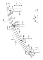
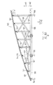
図1は、本発明の実施の一形態の建造物の屋根構造体50の主要な構成を示し、妻側から見た断面図である。また図2は、図1の屋根構造体50をより広範囲に示した断面図である。屋根構造体50は、建造物の屋根部分の構造である。屋根構造体50は、湾曲した屋根形状に形成される。屋根構造体50は、複数の母屋51と垂木52と固定部材53と野地板54とを含んで構成される。
【0037】
垂木52は、複数の母屋51間にわたって張架され、弾発的に湾曲した状態で、固定部材53によって各母屋51と固定される。また野地板54が、張架された垂木52の上方A1に貼り付けられる。野地板54は、弾発的に湾曲した状態で、垂木52に固定される。さらに建造物50は、野地板54に瓦などの屋根葺材料55が取り付けられて屋根が形成される。
【0038】
屋根構造体50は、さらに小屋ばり58および小屋つか57を含む。ほぼ水平に延びる小屋ばり58は、柱56の上端部に固定される。小屋ばり58は、地面からほぼ垂直に延びる柱56に対して直行する方向に延びる。この小屋ばり58が延びる方向が、はり間方向Bとなる。小屋つか57は、小屋ばり58に固定され、小屋ばり58から上方A1に延びる。小屋つか57は、はり間方向Bに並んで複数設けられ、屋根形状に応じてその長さが段階的に異なって形成される。したがって小屋ばり58に取り付けられた状態の小屋つか57は、その上端部の高さ位置が各小屋つか57ごとに異なって段階的に設けられる。
【0039】
各母屋51は、各小屋つか57の上端部ごとに設けられる。各小屋つか57は、その高さ位置が段階的に異なるので、各母屋51の高さ位置は、小屋つか57に応じて多段に配置される。母屋51は、けた行方向C、すなわち小屋つか57の軸線と小屋ばり58の軸線とを含む仮想一平面に対してほぼ垂直な方向に延びる角材である。また建造物において、小屋つか57の軸線と小屋ばり58の軸線とを含む仮想一平面に平行な面を妻側とする。また高さ位置は、地面から上端部までの位置である。
【0040】
本実施の形態では、はり間方向一方側B1の母屋51は、はり間方向他方側B2の母屋51に比べて、下方A2に配置される。垂木52は、各母屋51に当接するように弾発的に積極的に湾曲される。垂木52は、はり間方向一方側B1になるにつれて、下方A2に傾斜して延びる。垂木52は、この積極的に曲げられた状態で、各母屋51に固定部材53によって固定される。したがって垂木52は、各母屋51の高さ位置および母屋間のはり間方向Bの間隔に応じて、所定の形状に曲げられる。固定部材53は、弾発的に湾曲された状態の垂木52が延びる方向Dに対して法線方向E、すなわち垂木52の厚み方向に、垂木52を挿通して、垂木52を母屋51に固定する。また屋根構造体50は、複数の小屋つか57を連結する小屋筋かい59が設けられる。小屋筋かい59と小屋つか57とは、斜めに連結されてトラス構造を形成する。
【0041】
本実施の形態の屋根構造体50は、木造建造物の屋根部分の構造である。母屋51、垂木52および野地板54は木材から成る。垂木52は、母屋51に弾発的に湾曲させるために、その厚さが薄く形成される。具体的には垂木52は、厚さ30mm、幅60mm、長さ約4mの角材が用いられる。特に垂木52は、やわらかい杉材が用いられる。また母屋51は、断面の一辺が90mmの方形角材が用いられる。野地板54は、たとえば耐水合板が2枚重ねられ、厚さ9mm以上12mmの曲げ性を有するベニヤ合板などが用いられる。また屋根葺材料として、アスファルトルーフィングが葺かれ、その上面に瓦またはガルバリウム鋼板金属板等が設けられる。
【0042】
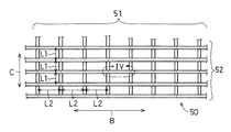
図3は、母屋51および垂木52の一部を示す屋根構造体50の平面図である。複数の母屋51が、けた行方向Cに延び、はり間方向Bに並んで配置される。この複数の母屋51の上端部に、はり間方向Bに延びる垂木52がけた行方向Cに並んで配置される。したがって屋根構造体は、各母屋51と各垂木52とによって格子状に形成される。屋根構造体50は、垂木間52に野地板54が架設されて、屋根面を形成し、屋根葺材料が屋根面に貼り付けられることによって、屋根が形成される。たとえば湾曲した屋根形状を形成する場合、垂木52のけた行方向Cの間隔L1は400mmであり、母屋間のはり間方向Bの間隔L2は約900mmmである。
【0043】
図4は、図3のセクションIVを拡大して示す平面図である。垂木52と母屋51とは、固定部材53によって固定され、上方A1から垂木52を厚み方向に挿通して母屋51と連結される。母屋51と垂木52とを連結する箇所には、2本以上の固定部材53が、けた行方向Cに並んで配置される。固定部材53は、たとえば外ねじ部材であり、すりわり付きさら木ねじ(以下ビス53とする)が用いられ、具体的には、長さ約65mm、ねじ部のよび径3mm、さら部最大直径8mmの亜鉛めっきビスが用いられる。このようなビスを固定部材53に用いることによって、ビスに形成されるねじ山によって、垂木52と母屋51との結合力を高めることができる。
【0044】
図5は、図1のセクションVを拡大して垂木52と母屋51との近傍を示す断面図である。ビス53は、弾発的に湾曲された状態の垂木52が延びる方向Dに対して法線方向E、すなわち垂木52を厚み方向に挿通して、垂木52を母屋51に固定する。垂木52がはり間方向Bに対して傾斜している部分では、垂木52は、母屋51の隅部60に当接する。垂木52と当接する母屋51の隅部60は、垂木52の湾曲具合によって異なる。図5に示すように、垂木52が屋根構造体外方に向かって突出して湾曲する場合は、母屋51の軒側上方の隅部60で垂木52と当接する。ビス53の先端部は、垂木52の上面から垂木52を厚み方向Eに螺進し、母屋51の隅部60付近から母屋52に螺着する。ビス53は、母屋51の中心に向かって延び、母屋に形成される複数の年輪を直交する方向に延びることが望ましい。
【0045】
また母屋51は、断面が方形の角材であるとしたが、母屋51の隅部60を、垂木52の湾曲具合に応じて削ってもよい。これによって垂木52は、母屋51と面接触することができる。垂木51が母屋51と面接触することによって、垂木52にかかる集中荷重を分散することができる。またビス53が、垂木52と母屋51との当接面から母屋51に挿入することによって、垂木52と母屋51との間に露出するビス53部分がなく、垂木52と母屋51とを好適に固定することができる。さらに垂木52が母屋51の削られた面に沿って湾曲することで、より滑らかな湾曲形状を有する屋根形状を形成することができる。
【0046】
図6は、図1のセクションVIを拡大して垂木52の継ぎ手部分64の近傍を示す断面図である。垂木52は、はり間方向Bに延びる複数の垂木部材52a,52bによって構成される。相互に隣接する2つの垂木部材52a,52bは、上方側と下方側とに配置される。本実施の形態では、上方側に配置される垂木部材52aは、上方A1かつはり間方向他方側B2側に位置する棟部寄りに配置され、下方側に配置される垂木部材52bは、下方A2かつはり間方向一方側B1側に位置する軒部寄りに配置される。
【0047】
相互に隣接する2つの垂木部材52a,52bのうち、棟部寄りに配置される垂木部材52aの下端部61には、下方A2になるにつれて下面61aに近接する方向に傾斜する第1接合面61bが形成される。第1接合面61bは、棟部寄りに配置される垂木部材52aの上面から下面にわたって傾斜して形成される。
【0048】
また前記隣接する2つの垂木部材52a,52bのうち、軒部寄りに配置される垂木部材52bの上端部62には、上方A1になるにつれて上面62aに近接する方向に傾斜する第2接合面62bが形成される。第2接合面62bは、軒部寄りに配置される垂木部材52aの上面から下面にわたって傾斜して形成される。
【0049】
棟部寄りに配置される垂木部材52aの最下端63、すなわち下面61aと第1接合面61bとの交差する端部が、母屋51の隅部60と当接する。隅部60は、母屋51の上端部かつ、はり間方向一方側B1の部分である。このように母屋51の隅部60に最下端63が当接される状態で、棟部寄りに配置される垂木部材52aの下端部61と軒部寄りに配置される垂木部材52bの上端部62とが、母屋51上で第1接合面61b上に第2接合面62bが重ねられ、継ぎ手部分64を構成する。
【0050】
この継ぎ手部分64が、ビス53によって母屋51に固定される。継ぎ手部分64では、ビス53の先端部は、軒部寄りの垂木部材52bの上面から螺進し、垂木52の厚み方向に挿通する。またビス53の先端部は、第1および第2の接合面61b,62bを通過し、母屋51のはり間方向B中央位置51aから母屋51に螺着する。ビス53が棟部寄りに配置される垂木部材52aを挿通する長さh1と、ビス53が軒部寄りに配置される垂木部材52bを挿通する長さh2とがほぼ均等になる位置に挿入されることが好ましい。
【0051】
また上述のように母屋51の隅部60が、湾曲屋根形状に沿って削られている場合、棟部寄りに配置される垂木部材52aと軒部寄りに配置される垂木部材52bとが、ともに隅部60で部分的に当接することが望ましい。これによって棟部寄りの垂木部材52aの最下端63が、母屋51と一箇所で当接することを防止し、垂木52が、継ぎ手部分64から破損することを防止することができる。
【0052】
さらに棟部寄りに配置される垂木部材52aの下面61aの一部を隅部60に当接させることが好ましい。これによって棟部寄りに配置される垂木部材52aを母屋51に当接させた状態で、軒部寄りに配置される垂木部材52bを重ねることによって、ビス53によって下方A2に押し付けて、母屋51に固定することができる。これによって第1の接合面と第2の接合面との隙間を無くして、垂木部材同士を連結することができる。
【0053】
また相互に隣接する2つの垂木部材52a,52bにおいて、棟部寄りに配置される垂木部材52aの下端部61に第2の接合面が形成され、軒部寄りに配置される垂木部材52bの上端部62に第1の接合面が形成されてもよい。このような相互に隣接する2つの垂木部材52a,52bは、棟部寄りに配置される垂木部材52aの下端部61には、上方A1になるにつれて上面に近接する方向に傾斜する第2接合面が形成される。第2接合面は、棟部寄りに配置される垂木部材52aの上面から下面にわたって傾斜して形成される。また前記隣接する2つの垂木部材52a,52bのうち、軒部寄りに配置される垂木部材52bの上端部62には、下方A2になるにつれて下面に近接する方向に傾斜する第1接合面が形成される。第2接合面は、軒部寄りに配置される垂木部材52aの上面から下面にわたって傾斜して形成される。
【0054】
以上のように本実施の形態によれば、垂木51を弾発的に湾曲させた状態で、母屋52に固定するので、小屋つか57の長さおよびピッチを変更することによって、垂木52の湾曲具合を容易に調整することができる。したがって従来のように、屋根形状に合わせて特別に、垂木52を加工する必要がなく、安価に屋根構造体を形成することができる。野地板54を湾曲させた状態で、垂木51に固定することによって、さらに滑らかな湾曲形状を有する屋根形状を得ることができる。
【0055】
またビス53が厚み方向に垂木52を挿通することによって、垂木52から突出するビス53の部分を多くすることができ、母屋51に螺着するビス部分を増やすことができる。母屋51に螺着するビス53部分を増やすことによって、母屋51と垂木52との結合をより強力にすることができる。またビス53が隅部60付近から母屋15に挿入することによって、垂木52と母屋51との間の部分に露出するビス53部分を減らすことができる。これによって母屋51に螺着するビス53部分を増やすことができる。さらにビス53は、ねじ山が形成されるので、螺着されるビス53と母屋51との摩擦抵抗を増やすことができる。したがってビス53は、垂木52が湾曲された状態から復元しようとする復元力に抗して、垂木52を母屋51に確実に固定することができる。このようなビス53をけた行方向Cに複数配置することによって、さらに確実に垂木52を母屋51に確実に固定することができる。
【0056】
図7は、本発明の実施の他の形態の建造物の屋根構造70の主要な構成を示し、妻側から見た断面図である。また図8は、図7の屋根構造体70をより広範囲に示した断面図である。図7および図8に示す屋根構造体70は、図1に示す屋根構造体50と類似しており、同様の構成については説明を省略し、図1に示す屋根構造体50と同様の参照符号を付す。屋根構造体70は、はり間方向Bに並んで、上方に延びる小屋つか57ごとに、けた行方向Cに延びる母屋51が固定される。母屋51の上端部には、上下方向A1,A2に2層の垂木71,72が積層されて設けられる。
【0057】
2層の垂木71,72は、弾発的に湾曲した状態で、ビス53b,53cによって母屋51に固定される。上方側の垂木71の上面には、野地板54が屋根構造体70を上部からふさぐように配置される。野地板54に、瓦などの屋根葺材料55が設けられることによって、屋根が形成される。前述の屋根構造体50と同様に、垂木71,72が湾曲されて母屋51に固定されるので、屋根形状に応じた垂木を加工する必要がなく、容易に湾曲した屋根形状を有する屋根構造体70を形成することができる。
【0058】
下方側の垂木72は、前述の屋根構造体50と同様に、ビス53cによって、母屋51に固定される。また下方側の垂木72の上面に、上方側の垂木71が固定される。上方側の垂木71も下方側の垂木72と同様にビス53bによって、母屋51に固定される。
【0059】
下方側の垂木72は、複数の母屋間にわたって架橋される複数の垂木部材72a,72bによって構成される。複数の垂木部材72a,72bは、第1接合面および第2接合面が形成され、第1接合面および第2接合面が重なる継ぎ手部分74が構成される。ビス53cは、継ぎ手部分74を挿通して母屋51に螺着する。これによって垂木部材72a,72bが互いに連結された状態で、下方側の垂木72が母屋51に固定される。
【0060】
上方側の垂木71も同様に、複数の母屋間にわたって架橋される複数の垂木部材71a,71bによって構成される。複数の垂木部材71a,71bは、上述の屋根構造体50の垂木52と同様に、第1接合面および第2接合面が形成され、第1接合面および第2接合面が重なる継ぎ手部分73が構成される。ビス53bは、継ぎ手部分73を挿通し、さらに下方側の垂木72を挿通して、母屋51に螺着する。これによって垂木部材71a,71bが互いに連結した状態で、上方側の垂木71と下方側の垂木72および母屋51とが固定される。
【0061】
上方側の垂木71は、下方側の垂木72と固定するための垂木連結ビス53aが螺着されて、下方側の垂木72に固定される。垂木連結ビス53aは、はり間方向Bにおいて、隣接する2つの母屋51の間にほぼ等間隔に2つ設けられる。垂木連結ビス53aは、上方側の垂木71の上面から上方側の垂木71を厚み方向に挿通し、下方側の垂木72に螺着する。これによって上下方向に積層される2つの垂木71,72は、上下方向に隙間なく固定される。
【0062】
下方側の垂木72の継ぎ手部分74の上方A1には、上方側の垂木71の垂木部材が配置される。これによって下方側の垂木72の継ぎ手部分74に生じる凹凸を、上方側の垂木部材が覆い、下方側の垂木72の継ぎ手部分74の凹凸の影響を低減することができる。
【0063】
また上方側の垂木71の継ぎ手部分73の下方には、下方側の垂木72の垂木部材が配置される。これによって上方側の垂木71の継ぎ手部分73は、下方側の垂木部材の滑らかな面に面接触して固定されるので、上方側の垂木71の継ぎ手部分73に生じる凹凸を低減することができる。このように継ぎ手部分の位置を違えて配置することによって、上層の垂木は、継ぎ手部分による凹凸の影響を少なくし、滑らかな面を有することができる。
【0064】
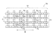
図9は、母屋51および垂木72の一部を示す屋根構造体70の平面図である。屋根構造体70は、複数の母屋51が、けた行方向Cに延び、はり間方向Bに並んで配置される。下方側の垂木72は、複数の母屋51の上端部に固定される。また下方側の垂木72は、はり間方向Bに延び、けた行方向Cに並んで配置される。下方側の垂木72の上方には、上方側の垂木71が積層される。上方側の垂木71は、下方側の垂木72と同様に、はり間方向Bに延び、けた行方向Cに並んで配置される。図9に示すように、各層を成す垂木71,72の継ぎ手部分73,74は、はり間方向Bに位置を違えて配置される。
【0065】
また下方側の垂木72を母屋51に固定するビス53cは、けた行方向Cに2列以上並んで配置される。上方側の垂木71を母屋51および下方の垂木72に固定するビス53bおよび垂木連結用ビス53aも同様に、けた方向Cに2列以上並んで配置される。ビス53b,53cは、母屋上に配置され、そのはり間方向の間隔は、約900mmである。また垂木連結用ビス53aは、たとえば約300mm間隔で設けられる。
【0066】
図10は、図7の屋根構造体70のセクションXを拡大して示す断面図である。母屋51には、下方側の垂木72を母屋に固定するための下方側のビス53cと、上方側の垂木71を母屋51に固定するための上方側のビス53bとの2つのビス53b,53cが螺着される。下方側のビス53cと上方側のビス53bとは、それぞれ挿通する垂木71,72を厚み方向に挿通し、はり間方向Bにずれた位置に配置される。下方側のビス53cは、母屋51の隅部60付近に螺着される。また上方側のビス53bは、下方側のビス53cよりも棟部側B2部分に螺着される。母屋51は、図1に示す屋根構造体50と同様に、湾曲形状に応じて一部が削られている。
【0067】
以上のように本実施の形態によれば、上述の図1に示す屋根構造体50と同様の効果を得ることができる。さらに垂木71,72を上下に積層することによって、瓦などの重量の大きい材質の屋根葺材料が積載された場合でも、屋根構造体が耐えうる強度を向上することができる。また垂木連結ビス53aが、上下の垂木71,72を複数の箇所で結合することによって、垂木間に上下方向の隙間をなくすることができる。これによって上方側の垂木71に作用する荷重を、分散して下方側の垂木72に伝えることができ、垂木全体の強度を向上することができる。また垂木を2層に積層することによって、継ぎ手部分に生じる凹凸の影響を少なくして、より滑らかな屋根形状を有する屋根構造体を建造することができる。
【0068】
図11は、本発明の屋根構造体70の建造工程を示す断面図であり、図11(1)から図11(8)の順に建造工程が行われる。図11(1)は土台81が敷き込まれた状態を示し、図11(2)は柱が立設された状態を示し、図11(3)は、2階の床組構造が形成された状態を示し、図11(4)は、小屋つか57および母屋51が取り付けられた状態を示し、図11(5),11(6),11(7)は、垂木部材が取り付けられる状態を順に示し、図11(8)は、建造された屋根構造体70を示す。また図12は、屋根構造体70の建造工程を示すフローチャートである。
【0069】
屋根構造体70の建造工程は、まずステップs0において、建造者が、屋根構造体70に用いられる小屋つか57、垂木52および母屋52などの屋根構造体70を建造するための部材を調達するなどの準備を行う。このとき小屋つか57は、その長さが屋根形状に応じて予め加工される。このような準備工程が完了するとステップs1に進む。
【0070】
ステップs1では、建造者が、屋根構造を建造するための基礎工事と土台敷き込みとを行う。これによって図11(1)に示すように、屋根構造体70は、建造者によって、基礎部分80が形成され、基礎部分80に土台81および火打ち土台が敷き込まれる。土台81が敷きこまれるとステップs2に進む。
【0071】
ステップs2では、建造者によって、図11(2)に示すように、柱が立設される。建造者は、通し柱56を立設し、次に管柱を立設する。次にステップs3に進む。ステップs3では、建造者が、管柱の上端部に胴差しを取り付ける。胴差しが取り付けた後に、梁および火打ち梁が取り付け、いわゆる軸組構造を形成する。このように軸組構造が形成した後、根太を取り付け、2階の床板82を張り、図11(3)に示すように、2階の床組構造を形成する。建造者が床板82を形成した後、ステップs4に進む。
【0072】
ステップs4では、図11(4)に示すように、屋根構造体70は、小屋組構造の形成が行われる。建造者によって、通し柱56の上端部に軒けた83が、けた行方向に延びて配置される。また軒けた83の延びる方向と直行する方向に延びる小屋ばり58が、通し柱56の上端部に配置される。次に小屋ばり58の上部に、小屋つか57が立設される。各小屋つか57は、屋根形状に応じて上端部の高さ位置が多段的になるように配置される。次に母屋51が、小屋つか57の上端部に取り付けられる。また小屋つか57の最も上端部に位置する部分には、けた行方向Cに延びる棟木84が取り付けられ、ステップs5に進む。
【0073】
ステップs5では、建造者が、母屋51の上端部に第1の垂木72を取り付ける。第1の垂木72は、複数の垂木部材から構成される。まず図11(5)に示すように、垂木部材72bを、複数の母屋51間に張架させ、はり間方向一方側B1の軒けた83aからはり間方向他方側B2にむけて、各母屋51に沿って湾曲させる。このとき垂木部材72bの上端部、すなわちはり間方向他方側B2の端部を母屋上に位置させる。
【0074】
次に湾曲された状態の垂木部材72bの上端部以外の部分を、ビス53によって母屋51に固定する。次に軒寄りに配置される垂木部材72bに対して、はり間方向他方B2側に、別の垂木部材72aを配置する。したがって前記別の垂木部材72aは、軒寄りに配置される垂木部材72bに比べて棟寄りに配置される。
【0075】
次に上述の2つの隣接して配置される垂木部材72a,72bのうち、棟寄りに配置される垂木部材72aの下端部と、軒寄りに配置される垂木部材72bの上端部とを重ねて、図6に示す垂木72の継ぎ手部分74を構成する。軒寄りに配置される垂木部材72bの上端部が母屋51上に配置されるので、継ぎ手部分74は、母屋51上に配置される。また本実施の形態では、棟寄りに配置される垂木部材72aの下端部は、はり間方向一方側B1端部であり、軒寄りに配置される垂木部材72bの上端部は、はり間方向他方側B2端部となる。
【0076】
次にビス53cによって継ぎ手部分74を母屋51に固定する。次に2つの隣接して配置される垂木部材72a,72bのうち、棟寄りに配置される垂木部材72aを複数の母屋51間に張架させ、母屋51に沿って湾曲させる。このとき垂木部材72aのはり間方向他方側B2の端部を母屋上に位置させ、湾曲された状態の垂木部材72aのはり間方向他方側B2の端部以外を、ビス53cによって母屋51に固定する。
【0077】
次に、さらに別の垂木部材を前述の垂木部材72aに隣接させて前述と同様に連結する。このように複数の垂木部材を順に連結し、はり間方向他方側B2の軒けた83bまで形成し、図11(6)に示すように、湾曲した第1の垂木72を形成する。湾曲した垂木72を形成した後、ステップs6に進む。
【0078】
ステップs6では、第1の垂木72の上面に第2の垂木71を取り付ける。第2の垂木71は、複数の垂木部材から構成される。まず図11(7)に示すように、はり間方向他方側B2の軒けた83b上方から、はり間方向一方側B1に垂木部材71aを配置する。このとき垂木部材71aのはり間方向他方側B2の端部を母屋51上に配置する。
【0079】
次に建造者は、前述の垂木部材71aを第1の垂木の形状に沿わせて湾曲させ、湾曲させた状態でビス53bによって固定する。ビス53bは、母屋上で第1の垂木72を厚み方向に挿通して、母屋51に螺着する。また建造者は、母屋間に垂木連結ビス53aを挿入し、第1の垂木72と垂木部材71aとを固定する。垂木連結ビス53aは、垂木部材71aを挿通して、第1の垂木72に螺着する。
【0080】
次にステップs5と同様に、複数の垂木部材によって形成される継ぎ手部分をビス53cによって連結し、湾曲した第2の垂木71を形成する。このとき第1の垂木72と第2の垂木71とは、異なった方向から連結されて形成されることによって、はり間方向Bに対して、第1の垂木72と第2の垂木71とで、継ぎ手部分を異なった位置に配置することができる。次にステップs7に進む。
【0081】
ステップs7では、野地板54が弾発的に湾曲した状態で、第2の垂木71に取り付けられる。また屋根構造体70を補強するために、トラス部材である筋かい84および小屋筋かい59が取り付けられる。次に野地板54に瓦などの屋根葺材料55が取り付けられ、ステップs8に進み、ステップs8で屋根構造体70の建造工程が終了する。
【0082】
以上のように、屋根構造体70を建造することによって、従来の小屋組構造とほぼ同様な建造工程および建造方法を用いることができる。したがって湾曲した屋根形状を有する屋根構造体70を建造するために、特別な構造を必要とせず、容易に建造することができる。また第1の垂木を構成する垂木部材を固定する方向と、第2の垂木を構成する垂木部材を固定する方向を異ならせることによって、垂木の継ぎ手部分を上下の垂木において容易に異ならせることができる。
【0083】
図13は、さらに本発明の実施の他の形態の屋根構造体90の構成を示し、妻側から見た断面図である。図13に示す屋根構造体90において、図1に示す屋根構造体50と同様の構成については、同様の符号を付し、説明を省略する。図13に示すように、屋根構造体90は、上方に傾斜して延びる登り梁91が柱56間に設けられる。この登り梁91に複数の小屋つか57が固定される。小屋つか57は、はり間方向Bに並んで配置される。また小屋つか57の上端部の高さ位置は、屋根形状に応じて多段的になるように固定される。
【0084】
小屋つか57は、その上端部に母屋51が、各小屋つか57ごとに固定される。母屋51は、けた行方向Cに延びる。屋根構造体90は、図1に示す屋根構造体50と同様に、垂木92a、92bが弾発的に湾曲させた状態で、母屋51の上端部に、ビス53によって固定される。このように湾曲された垂木92a、92bに野地板および屋根葺材料が取り付けられることによって、屋根が形成される。
【0085】
屋根構造体90の垂木92a、92bは、はり間方向Bに2つに分割されて形成され、はり間方向一方側B1の垂木92aと、はり間方向他方B2側の垂木92bとは、異なった湾曲形状を有する。また、はり間方向一方側B1の垂木92aと、はり間方向他方B2側の垂木92bとは、上端部の高さ位置が異なって形成される。これによって屋根構造体90の屋根形状は、上下方向に段差が形成される。
【0086】
図14は、さらに本発明の実施の他の形態の屋根構造体の屋根形状100,101,102,103の概略を示す正面図である。本実施の形態によって用いられる屋根構造体は、外方に向かって突出して湾曲される屋根形状のほかに、湾曲する屋根形状を有する建造物全般に用いることができる。たとえば屋根構造体の屋根形状は、外方に向かって突出して湾曲されるほかに、図14(1)に示すように、屋根構造体の屋根形状100は、内方に向かって突出して湾曲して形成されてもよい。また図14(2)に示すように、屋根構造体の屋根形状101は、上下方向A1,A2に段差hが形成されるとともに、はり間方向一方側B1の屋根101Aが直線状に延び、はり間方向他方側B2側の屋根101Bが外方に湾曲して延びてもよい。また図14(3)に示すように、屋根形状102は、上端部102Cが、はり間方向Bの中央でなくてもよく、はり間方向一方側B1の屋根102Aが内方に向かって突出して湾曲し、はり間方向他方側B2の屋根102Bが外方に湾曲して延びてもよい。また図14(4)に示すように、屋根形状103は、上方側A1の屋根103Aと下方側A2の屋根103Bとで湾曲形状が異なり、鏡餅の断面形状のように、上方側の屋根103Aよりも下方側の屋根103Bの曲率が大きく形成されてもよい。また垂木が屋根構造体内方に向かって突出して湾曲する場合は、図5に示す棟側上方の隅部65で当接することが好ましい。これによって垂木は、滑らかに湾曲することができる。以上のような図13および図14に示す屋根構造体であっても、図1および図7に上述した屋根構造体50,70と同様の効果を得ることができる。
【0087】
また上述の発明の実施の形態は、発明の例示に過ぎず、発明の範囲内で構成を変更することができる。たとえば屋根構造体は、特に木造が好ましいが、木造でなくてもよく、一部が鉄骨構造であってもよい。また小屋組構造は、和小屋でなくてもよく洋小屋であってもよい。
【0088】
また母屋51の隅部60に垂木52,71が延びる方向に、垂木52,71と同等の幅を有する切り欠きを設けてもよい。これによって垂木52,71は、切り欠きに嵌め込むことによって、けた行方向Cに容易に位置決めすることができる。垂木52,71を容易に位置決めすることができるので、垂木52,71を湾曲させた状態で、母屋51に結合することが容易に行うことができる。
【0089】
また母屋間のピッチを縮めることによって屋根構造体の強度をさらに高めることができる。たとえば母屋間のはり間方向Bのピッチを900mmから600mmにすることによって、屋根葺材料に対する十分な強度を得ることができる。また、垂木の厚さを厚くしてもよく、たとえば厚さ30mm、幅90mmである垂木の断面形状を、厚さ45mm、幅90mmとすることによって屋根構造体の強度を高めることができる。また野地板の厚みを増してもよく、たとえば厚さ12mmである野地板の厚さを15mmないし18mmにしてもよい。また垂木を3層にしてもよい。
【0090】
【発明の効果】
請求項1記載の本発明によれば、各屋根形状に応じて特別に垂木の形状を加工する必要がなく、屋根形状にかかわらず、共通な垂木を用いることができる。これによって共通化された垂木を用いることができるので、垂木の材料コストを削減し、屋根構造体建造に必要な建造費用を低減させることができる。
また継ぎ手部分では、一方の垂木部材と他方の垂木部材とを挿通して、互いの垂木部材を1つの固定部材によって連結することができる。また継ぎ手部分を母屋に固定することによって、継ぎ手部分の上下移動を規制し、継ぎ手部分での強度を向上させることができる。このように垂木において強度が低下する継ぎ手部分を母屋上に配置することによって、強度低下を防ぐことができる。
【0093】
また請求項2記載の本発明によれば、従来の小屋組工法とほぼ同様の工法において、小屋つかの長さおよびピッチを、任意の屋根形状に応じて調整するだけで、垂木の湾曲形状を整えることができ、湾曲した屋根形状を有する屋根構造体を容易に形成することができる。これによって湾曲した屋根形状を有する屋根構造体を複雑な登り梁および鉄骨梁などを有する複雑な構造にする必要がなく、屋根構造体建造に必要な建造費用を低減させることができる。
【0098】
また請求項3記載の本発明によれば、屋根構造体の建造方法が従来の小屋組工法とほぼ同様の工法であるので、湾曲した屋根形状にするために特別な構造を行う必要がなく、容易にかつ安価に屋根構造体を建造することができる。また第1の垂木と第2の垂木の固定する方向を異ならせることによって、各層を成す垂木の継ぎ手部分を、はり間方向に位置を違えて容易に配置することができる。
【0099】
これによって上層の垂木は、継ぎ手部分による凹凸の影響を少なくし、上面を滑らかに形成することができる。さらに野地板を弾発的に湾曲した状態で、垂木の上面に固定することによって、垂木による凹凸を低減し、上面がより滑らかな屋根形状を形成することができる。
また継ぎ手部分では、一方の垂木部材と他方の垂木部材とを挿通して、互いの垂木部材を1つの固定部材によって連結することができる。また継ぎ手部分を母屋に固定することによって、継ぎ手部分の上下移動を規制し、継ぎ手部分での強度を向上させることができる。このように垂木において強度が低下する継ぎ手部分を母屋上に配置することによって、強度低下を防ぐことができる。
【図面の簡単な説明】
【図1】本発明の実施の一形態の建造物の屋根構造体50の主要な構成を示し、妻側から見た断面図である。
【図2】図1の屋根構造体50をより広範囲に示した断面図である。
【図3】母屋51および垂木52の一部を示す屋根構造体50の平面図である。
【図4】図3のセクションIVを拡大して示す平面図である。
【図5】図1のセクションVを拡大して示す断面図である。
【図6】図1のセクションVIを拡大して垂木52の継ぎ手部分64の近傍を示す断面図である。
【図7】本発明の実施の他の形態の建造物の屋根構造70の主要な構成を示し、妻側から見た断面図である。
【図8】図7の屋根構造体70をより広範囲に示した断面図である。
【図9】母屋51および垂木72の一部を示す屋根構造体70の平面図である。
【図10】図7の屋根構造体70のセクションXを拡大して示す断面図である。
【図11】本発明の屋根構造体70の建造工程を示す断面図である。
【図12】屋根構造体70の建造工程を示すフローチャートである。
【図13】さらに本発明の実施の他の形態の屋根構造体90の構成を示し、妻側から見た断面図である。
【図14】さらに本発明の実施の他の形態の屋根構造体の屋根形状100,101,102,103の概略を示す正面図である。
【図15】従来の技術の建造物1の構成を妻側から見て示す断面図である。
【図16】他の従来の技術の屋根構造体20の一部を示し、妻側から見た断面図である。
【図17】さらに他の従来の技術の屋根構造体30の一部を示し、妻側から見た断面図である。
【図18】さらに他の従来の技術の屋根構造体40の一部を示し、妻側から見た断面図である。
【符号の説明】
50,70,90 屋根構造体
51 母屋
52 垂木
52a 上方側に配置される垂木部材
52b 下方側に配置される垂木部材
53 ビス
54 野地板
55 屋根葺材料
56 柱
57 小屋つか
58 小屋ばり
59 小屋筋かい
60 母屋51の隅部
61 上方側に配置される垂木部材の下端部
62 下方側に配置される垂木部材の上端部
63 上方側に配置される垂木部材52aの最下端
64 継ぎ手部分
A1 上方
A2 下方
B1 はり間方向一方向
B2 はり間方向他方向
C けた行方向[0001]
TECHNICAL FIELD OF THE INVENTION
The present invention relates to a roof structure of a building having a curved roof shape and a method of building the same.
[0002]
[Prior art]
FIG. 15 is a cross-sectional view showing the configuration of a
[0003]
The
[0004]
In the
[0005]
In the roof structure having such a conventional configuration, the roof shape is determined by a linearly extending
[0006]
FIG. 16 is a cross-sectional view showing a part of a
[0007]
The
[0008]
FIG. 17 is a cross-sectional view showing a part of a
[0009]
FIG. 18 is a cross-sectional view showing a part of a
[0010]
[Problems to be solved by the invention]
In the
[0011]
In the
[0012]
In the
[0013]
Therefore, an object of the present invention is to provide a roof structure of a building and a method of building the same, which can easily and inexpensively construct a curved roof shape.
[0017]
[Means for Solving the Problems]
The present invention provides a plurality of purlins in which the height position of the upper end portion is arranged in different stages according to the roof shape,
Rafters stretched across the upper end of each purlin,
A fixing member for fixing the rafter to the upper end of each purlin,
The rafter is fixed to the purlin by a fixing member in a state of being elastically curved,
The rafter is formed by a plurality of rafter members extending in a direction between beams and stretched between upper ends of a plurality of purlins, of two rafter members adjacent to each other, of a rafter member arranged on an upper side. At the lower end, a first joining surface inclined in the rafter member thickness direction is formed,
Of the two adjacent rafter members, a second joining surface that is inclined in the rafter member thickness direction is formed at an upper end portion of the rafter member arranged on the lower side,
The lower end of the rafter member arranged on the upper side and the upper end of the rafter member arranged on the lower side are brought into contact with the second joint surface being superimposed on the first joint surface to form a joint portion. This joint portion is fixed to the main building by the fixing member, and is a roof structure of a building.
[0018]
According to the present invention, the rafter is fixed to the purlin by the fixing member in a state of being elastically curved. Therefore, the rafters are resiliently deformed into a shape corresponding to the roof shape, so that it is not necessary to process the rafter shape according to each roof shape, even if the roof shape is curved. That is, a roof structure having an arbitrary roof shape can be easily formed by fixing a rafter having elasticity to a purlin in which the height of an upper end portion is differently arranged in multiple stages. In addition, since it is not necessary to process the shape of the rafter according to the roof shape, the rafter member used as the rafter can be shared regardless of the roof shape.
[0019]
In addition, by adjusting the height position of the purlin and the interval between the purlins appropriately according to the roof shape and fixing the rafter to the purlin, the rafter can be easily deformed into a predetermined curved roof shape. Further, by finely adjusting the height position of the purlin at the building site of the building, the dimensional error and the mounting error can be corrected, and a roof structure having an accurate roof shape can be formed.
In addition, a rafter is formed by the plurality of rafter members, and the first joint surface of the rafter member arranged on the upper side and the second joint surface of the rafter member arranged on the lower side overlap to form a joint portion. This joint portion is fixed to the purlin by a fixing member. Further, the fixing member penetrates the rafter in the thickness direction and couples the rafter to the purlin. Therefore, by inserting the rafter in the thickness direction of the fixing member, one rafter member and the other rafter member can be inserted at the joint portion, and the rafter members can be connected to each other.
Further, by fixing the joint portion on the purlin, when a load is applied from above the joint portion, the joint portion is fixed to the purlin, so that the joint portion can be prevented from being deformed downward. This prevents deformation of the joint portion, which is the joint portion, and improves the strength of the joint portion.
[0020]
The invention also provides a shed beam fixed to a substantially vertically extending column and extending substantially horizontally,
A plurality of sheds that extend substantially vertically and upward from the shed and are fixed at intervals to the shed;
A plurality of purlins extending in the row direction and fixed to the upper end of each cabin;
Rafters stretched across the upper end of each purlin,
A fixing member for fixing the rafter to the upper end of each purlin,
The upper end of a plurality of huts, the height position of which changes in multiple stages according to the roof shape, the rafters are elastically curved, and are fixed to each purlin by a fixing member,
The rafter is formed by a plurality of rafter members extending in a direction between beams and stretched between upper ends of a plurality of purlins, of two rafter members adjacent to each other, of a rafter member arranged on an upper side. At the lower end, a first joining surface inclined in the rafter member thickness direction is formed,
Of the two adjacent rafter members, a second joining surface that is inclined in the rafter member thickness direction is formed at an upper end portion of the rafter member arranged on the lower side,
The lower end of the rafter member arranged on the upper side and the upper end of the rafter member arranged on the lower side are brought into contact with the second joint surface being superimposed on the first joint surface to form a joint portion. This joint portion is fixed to the main building by the fixing member, and is a roof structure of a building.
[0021]
According to the present invention, the height position of the shed can be easily adjusted by changing the length of the shed. Therefore, by providing the height positions of the plurality of sheds differently in multiple stages, the height position of the purlin fixed for each shed can be provided in multiple stages. The roof structure having a curved roof shape can be formed by the rafters being resiliently curved and stretched between the purlins where the height positions are provided in multiple stages.
Such a configuration is similar to a roof structure having an uncurved roof shape such as a gable roof or a ridge roof. Therefore, the building can be constructed with a roof structure almost similar to the roof structure that does not bend. That is, in the construction process almost the same as the conventional hut structure, the length and pitch of the shed can be adjusted by simply adjusting the length and pitch of the hut according to any roof shape, and the curved roof shape can be adjusted. A roof structure having the same can be easily formed.
Further, a rafter is formed by a plurality of rafter members, and each joint surface of the two rafter members overlaps to form a joint portion. This joint portion is fixed to the purlin by a fixing member. The fixing member penetrates the rafter in the thickness direction and couples the rafter to the purlin. Therefore, the fixing member can connect the rafter members by inserting one rafter member and the other rafter member at the joint portion.
Further, by fixing the joint portion on the purlin, when a load is applied from above the joint portion, the joint portion is fixed to the purlin, so that the joint portion can be prevented from being deformed. This prevents deformation of the joint portion, which is the joint portion, and improves the strength of the joint portion.
[0031]
Further, the present invention provides a hut beam extending substantially horizontally at a predetermined height position from the ground, preparing a plurality of huts having different lengths in multiple stages according to the roof shape, and using the hut beams as the hut beams. Standing almost perpendicular to the
A plurality of purlins extending in the direction of the girder are placed on each shed or above,
A rafter joint portion formed by two mutually adjacent rafter members is fixed to the purlin from one side between the beams to form a curved first rafter;
On the upper surface of the first rafter, a joint portion of the rafter composed of two rafter members adjacent to each other is fixed to the purlin from the other side in the direction between beams, and is shifted with respect to the first rafter. Placing the joint portion in position to form a curved second rafter;
A method for constructing a roof structure of a building, characterized in that a field board is elastically curved and fixed to an upper surface of a second rafter.
[0032]
According to the present invention, a plurality of huts whose lengths are changed in multiple stages according to the roof shape are prepared, and the plurality of huts are erected substantially perpendicular to the hut beams. Next, each purlin is placed on the hut or above. Since such a construction method is almost the same as the conventional hut assembly method, it is not necessary to perform a special structure to obtain a curved roof shape.
[0033]
Also, the first rafter is curved from one side in the direction between the beams, which is the direction in which the hut beam extends, and is fixed to the purlin by a fixing member to form a curved first rafter. Next, the second rafter is curved on the upper surface of the first rafter from the other side in the direction between the beams, and is fixed to the purlin by a fixing member, and the joint is located at a position shifted with respect to the first rafter. The portions are arranged to form a curved second rafter. At this time, the joint portions of the first and second rafters are fixed to the purlin.
[0034]
Therefore, when the rafter members are connected to form a rafter, the directions in which the rafter members are connected are different. Accordingly, when rafter members having substantially the same shape are used, the joint portions of the rafters forming each layer can be easily arranged at different positions in the direction between the beams. As a result, as described above, the rafters in the upper layer can reduce the influence of unevenness due to the joint portion and form the upper surface smoothly.
[0035]
Further, by fixing the field board to the upper surface of the rafter in a state of being elastically curved, unevenness due to the rafter can be reduced, and a roof shape having a smoother upper surface can be formed.
In addition, a joint portion constituted by rafter members adjacent to each other is fixed to the purlin. Since the joint portion is fixed to the purlin, it is possible to prevent the joint portion from being deformed when a load is applied from above the joint portion. This prevents deformation of the joint portion, which is the joint portion, and improves the strength of the joint portion.
[0036]
BEST MODE FOR CARRYING OUT THE INVENTION
FIG. 1 is a cross-sectional view showing a main configuration of a
[0037]
The
[0038]
The
[0039]
Each
[0040]
In the present embodiment, the
[0041]
The
[0042]
FIG. 3 is a plan view of the
[0043]
FIG. 4 is an enlarged plan view showing section IV of FIG. The
[0044]
FIG. 5 is an enlarged sectional view of section V in FIG. 1 showing the vicinity of the
[0045]
Although the
[0046]
FIG. 6 is an enlarged sectional view of section VI of FIG. 1 showing the vicinity of the
[0047]
Of the two
[0048]
Also, of the two
[0049]
The lowermost end 63 of the
[0050]
The
[0051]
When the
[0052]
Further, it is preferable that a part of the
[0053]
In the two
[0054]
As described above, according to the present embodiment, the
[0055]
In addition, by inserting the
[0056]
FIG. 7 is a cross-sectional view showing a main structure of a
[0057]
The two layers of
[0058]
The
[0059]
The
[0060]
Similarly, the
[0061]
The
[0062]
The rafter member of the
[0063]
Below the
[0064]
FIG. 9 is a plan view of the
[0065]
The
[0066]
FIG. 10 is a cross-sectional view showing an enlarged section X of the
[0067]
As described above, according to the present embodiment, the same effects as those of the
[0068]
FIG. 11 is a cross-sectional view showing a construction process of the
[0069]
In the construction process of the
[0070]
In step s1, the builder performs foundation work and foundation laying for building a roof structure. As a result, as shown in FIG. 11A, the
[0071]
In step s2, the erection column is erected by the builder, as shown in FIG. The builder erects the through
[0072]
In step s4, as shown in FIG. 11 (4), the
[0073]
In step s5, the builder attaches the
[0074]
Next, portions other than the upper end portion of the
[0075]
Next, of the two
[0076]
Next, the
[0077]
Next, another rafter member is connected adjacent to the
[0078]
In step s6, the
[0079]
Next, the builder curves the
[0080]
Next, similarly to step s5, the joint portions formed by the plurality of rafter members are connected by
[0081]
In step s7, the
[0082]
As described above, by constructing the
[0083]
FIG. 13 is a cross-sectional view showing the configuration of a
[0084]
The
[0085]
The
[0086]
FIG. 14 is a front view schematically showing roof shapes 100, 101, 102, and 103 of a roof structure according to another embodiment of the present invention. The roof structure used in the present embodiment can be used for all buildings having a curved roof shape in addition to a roof shape that protrudes outward and curves. For example, in addition to the roof shape of the roof structure protruding outward and being curved, as shown in FIG. 14A, the
[0087]
Further, the above-described embodiments of the invention are merely examples of the invention, and the configuration can be changed within the scope of the invention. For example, the roof structure is particularly preferably made of a wooden structure, but need not be a wooden structure, and may have a partially steel structure. The hut structure may not be a Japanese hut but may be a Western hut.
[0088]
A cutout having a width equivalent to that of the
[0089]
Further, the strength of the roof structure can be further increased by reducing the pitch between the purlins. For example, by setting the pitch in the beam direction B between the purlins from 900 mm to 600 mm, sufficient strength for the roofing material can be obtained. Further, the thickness of the rafter may be increased. For example, by setting the cross-sectional shape of the rafter having a thickness of 30 mm and a width of 90 mm to a thickness of 45 mm and a width of 90 mm, the strength of the roof structure can be increased. Further, the thickness of the field board may be increased, for example, the thickness of the field board having a thickness of 12 mm may be set to 15 mm to 18 mm. Also, the rafters may have three layers.
[0090]
【The invention's effect】
According to the first aspect of the present invention, it is not necessary to specially process the shape of the rafter according to each roof shape, and a common rafter can be used regardless of the roof shape. As a result, a common rafter can be used, so that the material cost of the rafter can be reduced and the construction cost required for building the roof structure can be reduced.
In the joint portion, one rafter member and the other rafter member can be inserted and the rafter members can be connected by one fixing member. Further, by fixing the joint portion to the purlin, the vertical movement of the joint portion can be restricted, and the strength at the joint portion can be improved. Thus, by arranging the joint portion of the rafter, whose strength is reduced, on the main roof, the strength can be prevented from being reduced.
[0093]
Further, according to the present invention as set forth in
[0098]
According to the third aspect of the present invention, since the method of constructing the roof structure is substantially the same as the conventional hut assembly method, it is not necessary to perform a special structure to obtain a curved roof shape. The roof structure can be easily and inexpensively constructed. Further, by making the directions in which the first rafter and the second rafter are fixed differently, it is possible to easily arrange the rafter joints forming the respective layers at different positions in the direction between the beams.
[0099]
As a result, the upper rafter can be formed with a smooth upper surface by reducing the influence of unevenness due to the joint portion. Further, by fixing the field board to the upper surface of the rafter in a state of being elastically curved, unevenness due to the rafter can be reduced, and a roof shape having a smoother upper surface can be formed.
In the joint portion, one rafter member and the other rafter member can be inserted and the rafter members can be connected by one fixing member. Further, by fixing the joint portion to the purlin, the vertical movement of the joint portion can be restricted, and the strength at the joint portion can be improved. Thus, by arranging the joint portion of the rafter, whose strength is reduced, on the main roof, the strength can be prevented from being reduced.
[Brief description of the drawings]
FIG. 1 is a cross-sectional view showing a main structure of a
FIG. 2 is a sectional view showing the
3 is a plan view of a
FIG. 4 is an enlarged plan view showing a section IV of FIG. 3;
FIG. 5 is an enlarged sectional view showing a section V of FIG. 1;
FIG. 6 is an enlarged sectional view of section VI of FIG. 1 showing the vicinity of a
FIG. 7 is a cross-sectional view showing a main structure of a
FIG. 8 is a cross-sectional view showing the
9 is a plan view of a
FIG. 10 is an enlarged sectional view showing a section X of the
FIG. 11 is a cross-sectional view illustrating a construction process of the
FIG. 12 is a flowchart showing a construction process of the
FIG. 13 is a sectional view showing the configuration of a
FIG. 14 is a front view schematically showing roof shapes 100, 101, 102, and 103 of a roof structure according to another embodiment of the present invention.
FIG. 15 is a cross-sectional view showing the configuration of a
FIG. 16 is a cross-sectional view showing a part of a
FIG. 17 is a cross-sectional view showing a part of a
FIG. 18 is a cross-sectional view showing a part of a
[Explanation of symbols]
50, 70, 90 roof structure
51 Purlin
52 rafters
52a A rafter member arranged on the upper side
52b rafter members arranged on the lower side
53 screws
54 Field Board
55 Roofing material
56 pillars
57 Tsukasa Haya
58 Shed
59 Oyasuji Kai
60 Corner of
61 Lower end of rafter member arranged on upper side
62 Upper end of rafter member arranged below
63 Lowermost end of
64 joint part
A1 Above
A2 below
B1 One direction between beams
B2 Beam direction other direction
C Digit line direction
Claims (3)
各母屋の上端部間にわたって張架される垂木と、
垂木を各母屋の上端部に固定する固定部材とを含み、
垂木は、弾発的に湾曲された状態で、固定部材によって母屋に固定され、
前記垂木は、はり間方向に延び、複数の母屋の上端部間にわたって張架される複数の垂木部材によって構成され、相互に隣接する2つの垂木部材のうち、上方側に配置される垂木部材の下端部には、垂木部材厚み方向に傾斜する第1接合面が形成され、
前記隣接する2つの垂木部材のうち、下方側に配置される垂木部材の上端部には、垂木部材厚み方向に傾斜する第2接合面が形成され、
前記上方側に配置される垂木部材の下端部と前記下方側に配置される垂木部材の上端部とは、第1接合面上に第2接合面を重ねた状態で当接されて継ぎ手部分を構成し、この継ぎ手部分が、前記固定部材によって母屋に固定されることを特徴とするの建造物の屋根構造体。A plurality of purlins in which the height position of the upper end portion is arranged in different stages according to the roof shape,
Rafters stretched across the upper end of each purlin,
A fixing member for fixing the rafter to the upper end of each purlin,
The rafter is fixed to the purlin by a fixing member in a state of being elastically curved,
The rafter is formed by a plurality of rafter members extending in a direction between beams and stretched between upper ends of a plurality of purlins, of two rafter members adjacent to each other, of a rafter member arranged on an upper side. At the lower end, a first joining surface inclined in the rafter member thickness direction is formed,
Of the two adjacent rafter members, a second joining surface that is inclined in the rafter member thickness direction is formed at an upper end portion of the rafter member arranged on the lower side,
The lower end of the rafter member arranged on the upper side and the upper end of the rafter member arranged on the lower side are brought into contact with the second joint surface being superimposed on the first joint surface to form a joint portion. A roof structure for a building, wherein the joint portion is fixed to the purlin by the fixing member.
小屋ばりからほぼ垂直かつ上方に延び、小屋ばりに間隔をあけて固定される複数の小屋つかと、
けた行方向に延び、各小屋つかの上端部に固定される複数の母屋と、
各母屋の上端部間にわたって張架される垂木と、
垂木を各母屋の上端部に固定する固定部材とを含み、
複数の小屋つかの上端部は、その高さ位置が屋根形状に応じて多段的に変化し、垂木は弾発的に湾曲された状態で、固定部材によって各母屋に固定され、
前記垂木は、はり間方向に延び、複数の母屋の上端部間にわたって張架される複数の垂木部材によって構成され、相互に隣接する2つの垂木部材のうち、上方側に配置される垂木部材の下端部には、垂木部材厚み方向に傾斜する第1接合面が形成され、
前記隣接する2つの垂木部材のうち、下方側に配置される垂木部材の上端部には、垂木部材厚み方向に傾斜する第2接合面が形成され、
前記上方側に配置される垂木部材の下端部と前記下方側に配置される垂木部材の上端部とは、第1接合面上に第2接合面を重ねた状態で当接されて継ぎ手部分を構成し、この継ぎ手部分が、前記固定部材によって母屋に固定されることを特徴とするの建造物の屋根構造体。A shed that is fixed to a column that extends almost vertically and that extends almost horizontally,
A plurality of sheds that extend substantially vertically and upward from the shed and are fixed at intervals to the shed;
A plurality of purlins extending in the row direction and fixed to the upper end of each cabin;
Rafters stretched across the upper end of each purlin,
A fixing member for fixing the rafter to the upper end of each purlin,
The upper end of a plurality of huts, the height position of which changes in multiple stages according to the roof shape, the rafters are elastically curved, and are fixed to each purlin by a fixing member,
The rafter is formed by a plurality of rafter members extending in a direction between beams and stretched between upper ends of a plurality of purlins, of two rafter members adjacent to each other, of a rafter member arranged on an upper side. At the lower end, a first joining surface inclined in the rafter member thickness direction is formed,
Of the two adjacent rafter members, a second joining surface that is inclined in the rafter member thickness direction is formed at an upper end portion of the rafter member arranged on the lower side,
The lower end of the rafter member arranged on the upper side and the upper end of the rafter member arranged on the lower side are brought into contact with the second joint surface being superimposed on the first joint surface to form a joint portion. A roof structure for a building, wherein the joint portion is fixed to the purlin by the fixing member.
けた行方向に延びる複数の母屋を、各小屋つか上に配置し、
相互に隣接する2つの垂木部材によって構成される垂木の継ぎ手部分を、はり間方向一方側から母屋に固定して、湾曲した第1の垂木を形成し、
前記第1の垂木の上面に、相互に隣接する2つの垂木部材によって構成される垂木の継ぎ手部分を、はり間方向他方側から母屋に固定して、前記第1の垂木に対して、ずれた位置に継ぎ手部分を配置して、湾曲した第2の垂木を形成し、
第2の垂木の上面に、野地板を弾発的に湾曲させて固定することを特徴とする建造物の屋根構造体の建造方法。At a predetermined height position from the ground, a hut beam extending substantially horizontally is provided, and a plurality of huts having different lengths are prepared in multiple stages according to the roof shape, and the huts are provided almost vertically to the hut beams. Erect,
A plurality of purlins extending in the direction of the girder are placed on each shed or above,
A rafter joint portion formed by two mutually adjacent rafter members is fixed to the purlin from one side between the beams to form a curved first rafter;
On the upper surface of the first rafter, a joint portion of the rafter composed of two rafter members adjacent to each other is fixed to the purlin from the other side in the direction between beams, and is shifted with respect to the first rafter. Placing the joint portion in position to form a curved second rafter;
A method for constructing a roof structure of a building, wherein a field board is elastically curved and fixed to an upper surface of a second rafter.
Priority Applications (1)
| Application Number | Priority Date | Filing Date | Title |
|---|---|---|---|
| JP2001171227A JP3550108B2 (en) | 2001-06-06 | 2001-06-06 | Roof structure of building and method of building the same |
Applications Claiming Priority (1)
| Application Number | Priority Date | Filing Date | Title |
|---|---|---|---|
| JP2001171227A JP3550108B2 (en) | 2001-06-06 | 2001-06-06 | Roof structure of building and method of building the same |
Publications (2)
| Publication Number | Publication Date |
|---|---|
| JP2002364114A JP2002364114A (en) | 2002-12-18 |
| JP3550108B2 true JP3550108B2 (en) | 2004-08-04 |
Family
ID=19013030
Family Applications (1)
| Application Number | Title | Priority Date | Filing Date |
|---|---|---|---|
| JP2001171227A Expired - Fee Related JP3550108B2 (en) | 2001-06-06 | 2001-06-06 | Roof structure of building and method of building the same |
Country Status (1)
| Country | Link |
|---|---|
| JP (1) | JP3550108B2 (en) |
-
2001
- 2001-06-06 JP JP2001171227A patent/JP3550108B2/en not_active Expired - Fee Related
Also Published As
| Publication number | Publication date |
|---|---|
| JP2002364114A (en) | 2002-12-18 |
Similar Documents
| Publication | Publication Date | Title |
|---|---|---|
| US10570614B2 (en) | Shear transfer system | |
| JP2020007827A (en) | Wooden unit type building structure and its assembly method | |
| US20200123763A1 (en) | Building and construction method for same | |
| JP4614151B1 (en) | Wooden truss beam structure | |
| JP3550108B2 (en) | Roof structure of building and method of building the same | |
| JP3657432B2 (en) | Roof roof structure and construction method | |
| JP2024157437A (en) | building | |
| US4091582A (en) | Trussed roof structure for prefabricated buildings | |
| JPH01315541A (en) | Roof truss | |
| US10385583B2 (en) | Shear transfer system | |
| JP2535656B2 (en) | Building structure | |
| JP4772428B2 (en) | Method for assembling roof truss members | |
| JP2514578B2 (en) | Mansard roof hut structure and construction method | |
| JP3391916B2 (en) | Ceiling panels and roof units | |
| JPH10169088A (en) | Roof structure and roof unit including the structure | |
| JP2535658B2 (en) | Building structure | |
| JP2003013538A (en) | Roof frame structure | |
| JPS645145B2 (en) | ||
| JP2024157434A (en) | building | |
| JP2000096758A (en) | Frame structure and construction method of the ridge roof | |
| JP2021147982A (en) | Ridge roof unit | |
| JPH0124246Y2 (en) | ||
| JP2004124397A (en) | Roof structure of house by roof panel | |
| JPH03271446A (en) | Roof truss structure | |
| JP2021165496A (en) | Roof structure and roof structure construction method |
Legal Events
| Date | Code | Title | Description |
|---|---|---|---|
| A521 | Written amendment |
Free format text: JAPANESE INTERMEDIATE CODE: A523 Effective date: 20040213 |
|
| TRDD | Decision of grant or rejection written | ||
| A01 | Written decision to grant a patent or to grant a registration (utility model) |
Free format text: JAPANESE INTERMEDIATE CODE: A01 Effective date: 20040406 |
|
| A61 | First payment of annual fees (during grant procedure) |
Free format text: JAPANESE INTERMEDIATE CODE: A61 Effective date: 20040422 |
|
| R150 | Certificate of patent or registration of utility model |
Free format text: JAPANESE INTERMEDIATE CODE: R150 |
|
| R250 | Receipt of annual fees |
Free format text: JAPANESE INTERMEDIATE CODE: R250 |
|
| FPAY | Renewal fee payment (event date is renewal date of database) |
Free format text: PAYMENT UNTIL: 20080430 Year of fee payment: 4 |
|
| FPAY | Renewal fee payment (event date is renewal date of database) |
Free format text: PAYMENT UNTIL: 20090430 Year of fee payment: 5 |
|
| LAPS | Cancellation because of no payment of annual fees |