JP3551994B2 - Multi-conductor transmission line - Google Patents
Multi-conductor transmission line Download PDFInfo
- Publication number
- JP3551994B2 JP3551994B2 JP31615095A JP31615095A JP3551994B2 JP 3551994 B2 JP3551994 B2 JP 3551994B2 JP 31615095 A JP31615095 A JP 31615095A JP 31615095 A JP31615095 A JP 31615095A JP 3551994 B2 JP3551994 B2 JP 3551994B2
- Authority
- JP
- Japan
- Prior art keywords
- conductor
- transmission line
- marker
- conductors
- striated body
- Prior art date
- Legal status (The legal status is an assumption and is not a legal conclusion. Google has not performed a legal analysis and makes no representation as to the accuracy of the status listed.)
- Expired - Fee Related
Links
Images



Landscapes
- Catching Or Destruction (AREA)
- Suspension Of Electric Lines Or Cables (AREA)
Description
【0001】
【発明の属する技術分野】
本発明は、標識部材を取付けた多導体送電線路に関するものである。
【0002】
【従来の技術】
多導体送電線路が鳥、特に保護鳥の生息地を通過する場合があり、このような多導体送電線路においては、鳥が衝突するのを防止する必要がある。また多導体送電線路にヘリコプターが衝突するのを防止する必要がある。さらに導電性の釣り竿等が多導体送電線路に接触すると感電事故が生じるのでこれを防止する必要がある。
【0003】
そこで従来は、図5(a)(b)に示すような標識部材3を多導体送電線路に取付けることが行われている。
この標識部材3は、導体を把持するリング部31と、該リング部31の下部に吊り下げられた円板状の標識片32とから構成されている。リング部31および標識片32はプラスチック等で形成されている。
【0004】
この標識部材3は、風によって標識片32がヒラヒラと動くことによって、鳥や人間に多導体送電線路の存在を知らしめ、これによって鳥やヘリコプターが多導体送電線路に衝突するのを防止すると共に釣り竿等が多導体送電線路に接触するのを防止するものである。
【0005】
【発明が解決しようとする課題】
しかしながら、従来の標識部材は、導体に吊り下げる構造であり、送電電圧が、例えば275KV以上の超高圧である場合、コロナ放電が発生し易いという問題があった。
【0006】
すなわち、送電電圧が275KV等と超高圧である場合、1相の導体は複数本の導体で構成されており、かかる多導体の各導体に標識リングを取付けると、特に多導体の下側に取付けた標識リングからコロナ放電が発生し易く、このためにラジオやテレビの電波障害を起こすという問題があった。
またコロナ放電の微小アーク放電により、標識片が損傷し落下してしまうという問題があった。
【0007】
【課題を解決するための手段】
本発明は上記問題点に鑑みてなされたもので、275KV以上の超高圧の多導体送電線路に使用してもコロナ放電を生じさせることなく、また鳥等の衝突や釣り竿等の接触を防止できる多導体送電線路を提供するものである。
【0008】
本発明の多導体送電線路は、多導体に沿わせて、標識部材を取付けた線条体を配置してなり、前記標識部材は、多導体を構成する各導体の外周面と接する円内に位置していることを特徴とするものである。
【0009】
多導体に沿わせて、標識部材を取付けた線条体を配置してなり、前記標識部材を、多導体を構成する各導体の外周面と接する円内に位置させることにより、標識部材を電位傾度の低い部分に設置することができるので、コロナ放電の発生を防止できる。また、標識体によって鳥や人間に送電線の存在を知らしめることができるので、鳥やヘリコプター等の衝突や釣り竿等の接触を防止することができる。
【0010】
【発明の実施の形態】
以下、本発明を図面を参照して詳細に説明する。
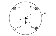
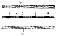
図1および図2は本発明を4導体送電線路に適用した場合であり、1A、1B、1C、1Dは4導体送電線路を構成する各導体、2は各導体1A、1B、1C、1Dの略中央部に位置しかつ各導体に沿って配置された線条体、3は線条体2の長手方向に所定間隔毎に取付けた標識部材である。
【0011】
4導体送電線路を構成する各導体1A、1B、1C、1Dは、鋼心上にアルミ素線を撚合わせた鋼心アルミ撚線や、インバ線上にアルミ素線を撚合わせた低弛度型の撚線導体が使用される。
【0012】
また、線条体2としては、アルミや鋼等の金属素線を撚合わせた金属撚線やプラスチック素線を撚合わせたプラスチック撚線の他、アルミや鋼等のロッド、グラスファイバーやカーボンファイバー等のロッドが使用できる。
この線条体2は、4導体送電線路を構成する各導体1A、1B、1C、1Dの略中央部に位置しておりかつ各導体に沿って配置されている。
【0013】
標識体3は、線条体2の長手方向に所定間隔をおいて取付けられており、その形状は図5(a)(b)に示したものと同じものである。
この標識体3は、図2に示すように、多導体を構成する各導体1A、1B、1C、1Dの外周面と接する円Xの内側に配置されている。
多導体を構成する各導体1A、1B、1C、1Dの外周面と接する円Xの内側は電位傾度が低いために、かかる位置に標識体3を配置しておけば、標識体3からコロナ放電が生じることがない。
【0014】
上記構成の多導体送電線路を構成するには、まず線条体2に標識体3を取付け、しかる後に線条体2を送電線路を構成する各導体1A、1B、1C、1Dの略中央部位置にかつ各導体に沿って配置すればよい。
このように、まず線条体2に標識体3を取付け、これを各導体1A、1B、1C、1Dの略中央部位置にかつ各導体に沿って配置すると、線条体2と標識体3を同時に所定位置に配置できるので、工事が簡単になるという利点がある。
なお、まず線条体2を所定位置に配置ししかる後に該線条体2に標識体3を取付けるようにしてもよいことは勿論である。
【0015】
図3は本発明に係る多導体送電線路の他の実施の形態を示すもので、前記実施の形態と異なる点は、各導体1A、1B、1C、1Dの外周および線条体2の外周にスパイラル状に線4を巻き付けたものである。
【0016】
このように、各導体1A、1B、1C、1Dの外周および線条体2の外周にスパイラル状に線4を巻き付けると、各導体1A、1B、1C、1Dおよび線条体2に生じる風騒音を減少させることができるという効果がある。
なお、スパイラル状の線4は、各導体1A、1B、1C、1Dの外周または線条体2の外周のいづれか一方のみに巻き付けるようにしてもよい。
【0017】
図4は本発明に係る多導体送電線路の他の実施の形態を示すもので、前記実施の形態と異なる点は、標識体3として、プラスチック筒を使用した点である。
このプラスチック筒は、線条体2に熱溶着や接着等で固定しておくものである。またプラスチック筒の取付け間隔は適宜選定するものである。
【0018】
なお上記の実施の形態においては、4導体の多導体送電線路に本発明を適用した場合について説明したが、本発明は、2導体、6導体、8導体等の多導体送電線路に適用できるものである。
【0019】
また、上記の実施の形態においては、線条体2を送電線路を構成する各導体1A、1B、1C、1Dの略中央部位置にかつ各導体に沿って配置したが、線条体2の位置は、特に限定するものではなく、各導体1A、1B、1C、1Dの外周面と接する円Xの内側または外側であってもよい。好ましくは、線条体2の位置は、各導体1A、1B、1C、1Dの外周面と接する円Xの内側である。かかる位置は電位傾度が低いからである。
【0020】
さらに、標識体3の形状やその取付け間隔等は特に限定するものではない。例えば標識体3は、テープ状のものを線条体2に巻き付けて形成してもよい。また標識体3には、光線を反射するアルミ箔を張り付けたり、目立つように赤色を塗ったり、蛍光発色塗料を塗ったりしておくことが好ましい。標識体3の形状の例としては、吊り凧のようなモービル的な動きをするもの、ストロボ・フラッシュのような閃光的発光をするもの、周囲の磁場を乱す強力磁石等であってもよい。
【0021】
【発明の効果】
以上のように、本発明にかかる多導体送電線路は、多導体に沿わせて、標識部材を取付けた線条体を配置してなり、前記標識部材は、多導体を構成する各導体の外周面と接する円内に位置していることを特徴とするものであるために、標識部材を電位傾度の低い部分に設置することができる。したがって標識部材からのコロナの発生を防止できる。また、標識体によって鳥や人間に送電線の存在を知らしめることができるので、鳥やヘリコプター等の衝突や釣り竿等の接触を有効に防止することができる。
【図面の簡単な説明】
【図1】本発明の第1の実施の形態を示す正面図である。
【図2】図1の側面図である。
【図3】本発明の第2の実施の形態を示す正面図である。
【図4】本発明の第3の実施の形態を示す正面図である。
【図5】標識リングを示すのもで、(a)は側面図、(b)は正面図である。
【符号の説明】
1A、1B、1C、1D 4導体送電線路を構成する各導体
2 線条体
3 標識部材
4 スパイラル状の線[0001]
TECHNICAL FIELD OF THE INVENTION
TECHNICAL FIELD The present invention relates to a multiconductor power transmission line to which a sign member is attached.
[0002]
[Prior art]
Multi-conductor power lines may pass through bird habitats, especially protected birds, and it is necessary to prevent birds from colliding in such multi-conductor power lines. It is also necessary to prevent the helicopter from colliding with the multiconductor transmission line. Further, if a conductive fishing rod or the like comes into contact with the multi-conductor transmission line, an electric shock accident occurs, and it is necessary to prevent this.
[0003]
Therefore, conventionally, a
The marking
[0004]
The
[0005]
[Problems to be solved by the invention]
However, the conventional sign member has a structure in which it is hung on a conductor, and has a problem that corona discharge is likely to occur when the transmission voltage is an extremely high voltage of, for example, 275 KV or more.
[0006]
That is, when the transmission voltage is as high as 275 KV or the like, the one-phase conductor is composed of a plurality of conductors. There is a problem that corona discharge is easily generated from the sign ring, which causes radio wave interference of radio and television.
In addition, there was a problem that the marker piece was damaged and dropped by the minute arc discharge of the corona discharge.
[0007]
[Means for Solving the Problems]
The present invention has been made in view of the above problems, and does not cause corona discharge even when used in an ultrahigh-voltage multiconductor transmission line of 275 KV or more, and can prevent collision of birds and the like and contact of fishing rods and the like. A multi-conductor transmission line is provided.
[0008]
The multi-conductor power transmission line of the present invention is arranged with a striated body attached with a sign member along the multi-conductor, and the sign member is located in a circle in contact with the outer peripheral surface of each conductor constituting the multi-conductor. It is characterized by being located.
[0009]
A striatum to which a marker member is attached is arranged along the multiconductor, and the marker member is positioned within a circle in contact with the outer peripheral surface of each conductor constituting the multiconductor, thereby causing the marker member to have a potential. Since it can be installed in a portion with a low inclination, the occurrence of corona discharge can be prevented. In addition, since the presence of the transmission line can be notified to birds and humans by the marker, collision of birds and helicopters and contact of fishing rods and the like can be prevented.
[0010]
BEST MODE FOR CARRYING OUT THE INVENTION
Hereinafter, the present invention will be described in detail with reference to the drawings.
1 and 2 show a case where the present invention is applied to a four-conductor power transmission line, where 1A, 1B, 1C, and 1D are conductors constituting a four-conductor power transmission line, and 2 is each of conductors 1A, 1B, 1C, and 1D. The
[0011]
Each of the conductors 1A, 1B, 1C, and 1D constituting the four-conductor power transmission line is a steel core aluminum stranded wire obtained by twisting an aluminum wire on a steel core, or a low sag type wire obtained by twisting an aluminum wire on an invar wire. Is used.
[0012]
The
The
[0013]
The
As shown in FIG. 2, the
Since the potential gradient is low inside the circle X in contact with the outer peripheral surface of each of the conductors 1A, 1B, 1C, and 1D constituting the multiconductor, if the
[0014]
In order to configure the multi-conductor power transmission line having the above-described configuration, first, the
As described above, first, the
Note that it is a matter of course that the
[0015]
FIG. 3 shows another embodiment of the multi-conductor power transmission line according to the present invention. The difference from the above-described embodiment is that the outer peripheries of the conductors 1A, 1B, 1C, 1D and the outer perimeter of the
[0016]
When the
The
[0017]
FIG. 4 shows another embodiment of the multi-conductor power transmission line according to the present invention. The difference from the above embodiment is that a plastic cylinder is used as the
The plastic tube is fixed to the
[0018]
In the above-described embodiment, the case where the present invention is applied to a four-conductor multi-conductor transmission line is described. However, the present invention can be applied to a two-conductor, six-conductor, eight-conductor, etc. multi-conductor transmission line. It is.
[0019]
In the above-described embodiment, the
[0020]
Further, the shape of the
[0021]
【The invention's effect】
As described above, the multi-conductor power transmission line according to the present invention has a striated body to which a sign member is attached along the multi-conductor, and the sign member has an outer periphery of each conductor constituting the multi-conductor. Since it is characterized by being located in a circle in contact with the surface, the marker member can be installed in a portion with a low potential gradient. Therefore, generation of corona from the sign member can be prevented. In addition, since the presence of the transmission line can be notified to birds and humans by the sign, the collision of birds and helicopters and the like and the contact of fishing rods and the like can be effectively prevented.
[Brief description of the drawings]
FIG. 1 is a front view showing a first embodiment of the present invention.
FIG. 2 is a side view of FIG.
FIG. 3 is a front view showing a second embodiment of the present invention.
FIG. 4 is a front view showing a third embodiment of the present invention.
5 (a) is a side view and FIG. 5 (b) is a front view showing a sign ring.
[Explanation of symbols]
1A, 1B, 1C, 1D Four conductors constituting a four-
Claims (1)
Priority Applications (1)
| Application Number | Priority Date | Filing Date | Title |
|---|---|---|---|
| JP31615095A JP3551994B2 (en) | 1995-12-05 | 1995-12-05 | Multi-conductor transmission line |
Applications Claiming Priority (1)
| Application Number | Priority Date | Filing Date | Title |
|---|---|---|---|
| JP31615095A JP3551994B2 (en) | 1995-12-05 | 1995-12-05 | Multi-conductor transmission line |
Publications (2)
| Publication Number | Publication Date |
|---|---|
| JPH09163563A JPH09163563A (en) | 1997-06-20 |
| JP3551994B2 true JP3551994B2 (en) | 2004-08-11 |
Family
ID=18073837
Family Applications (1)
| Application Number | Title | Priority Date | Filing Date |
|---|---|---|---|
| JP31615095A Expired - Fee Related JP3551994B2 (en) | 1995-12-05 | 1995-12-05 | Multi-conductor transmission line |
Country Status (1)
| Country | Link |
|---|---|
| JP (1) | JP3551994B2 (en) |
Families Citing this family (1)
| Publication number | Priority date | Publication date | Assignee | Title |
|---|---|---|---|---|
| JP6239702B1 (en) * | 2016-08-10 | 2017-11-29 | 古河電気工業株式会社 | Overhead electric wire and method for manufacturing the same |
-
1995
- 1995-12-05 JP JP31615095A patent/JP3551994B2/en not_active Expired - Fee Related
Also Published As
| Publication number | Publication date |
|---|---|
| JPH09163563A (en) | 1997-06-20 |
Similar Documents
| Publication | Publication Date | Title |
|---|---|---|
| US5687271A (en) | Shielded fiber optics cable for compatibility with high voltage power lines | |
| EP0489805B1 (en) | Retractable coiled electrical cable | |
| US6353177B1 (en) | Vibration resistant overhead electrical cable | |
| ES2090069T3 (en) | AIRLINE ELECTRIC CABLE WITH FIBROOPTICAL CONDUCTORS. | |
| CA2251500C (en) | Limiting electrical degradation of all-dielectric self supporting cables | |
| US4474133A (en) | Aircraft warning marker | |
| JPH09163563A (en) | Multi-conductor transmission line | |
| YU45996A (en) | INDUCTIVE ABSORPTION INJECTION FOR MICROWAVE RADIATION REMOVAL | |
| ES2304937T3 (en) | SPIRAL OF BALIZAJE FOR ELECTRICAL NETWORK. | |
| US4818825A (en) | Insulating spacers for use in gas-insulated electric apparatus | |
| JPH09200933A (en) | Multi-conductor transmission line | |
| JPH09117045A (en) | Multi-conductor sign and its mounting method | |
| JPS58355Y2 (en) | Overhead transmission line jumper device | |
| US4121045A (en) | Corona shielding by jumper assembly | |
| JPH0135571B2 (en) | ||
| JPH038018Y2 (en) | ||
| SU1660092A1 (en) | AIRLINE TRANSMISSION | |
| JPS58162911A (en) | Optical communication line for joint use of overhead line | |
| JP2949537B2 (en) | Reinforced lightning coil | |
| JPS6356114A (en) | Arc-resistant overhead grounding wire | |
| JPH038025Y2 (en) | ||
| JPH09247829A (en) | Overhead transmission line to prevent bird collision | |
| JPH038019Y2 (en) | ||
| JPS6329490B2 (en) | ||
| JPS591048B2 (en) | Low wind noise overhead power transmission line |
Legal Events
| Date | Code | Title | Description |
|---|---|---|---|
| A61 | First payment of annual fees (during grant procedure) |
Free format text: JAPANESE INTERMEDIATE CODE: A61 Effective date: 20040420 |
|
| R250 | Receipt of annual fees |
Free format text: JAPANESE INTERMEDIATE CODE: R250 |
|
| FPAY | Renewal fee payment (prs date is renewal date of database) |
Free format text: PAYMENT UNTIL: 20090514 Year of fee payment: 5 |
|
| FPAY | Renewal fee payment (prs date is renewal date of database) |
Free format text: PAYMENT UNTIL: 20100514 Year of fee payment: 6 |
|
| FPAY | Renewal fee payment (prs date is renewal date of database) |
Free format text: PAYMENT UNTIL: 20110514 Year of fee payment: 7 |
|
| FPAY | Renewal fee payment (prs date is renewal date of database) |
Free format text: PAYMENT UNTIL: 20110514 Year of fee payment: 7 |
|
| FPAY | Renewal fee payment (prs date is renewal date of database) |
Free format text: PAYMENT UNTIL: 20120514 Year of fee payment: 8 |
|
| LAPS | Cancellation because of no payment of annual fees |