JP3552012B2 - Variable buildings - Google Patents
Variable buildings Download PDFInfo
- Publication number
- JP3552012B2 JP3552012B2 JP06155697A JP6155697A JP3552012B2 JP 3552012 B2 JP3552012 B2 JP 3552012B2 JP 06155697 A JP06155697 A JP 06155697A JP 6155697 A JP6155697 A JP 6155697A JP 3552012 B2 JP3552012 B2 JP 3552012B2
- Authority
- JP
- Japan
- Prior art keywords
- movable frame
- main body
- variable building
- variable
- wall
- Prior art date
- Legal status (The legal status is an assumption and is not a legal conclusion. Google has not performed a legal analysis and makes no representation as to the accuracy of the status listed.)
- Expired - Fee Related
Links
Images

Landscapes
- Buildings Adapted To Withstand Abnormal External Influences (AREA)
Description
【0001】
【発明の属する技術分野】
本発明は、用途や規模、形態を容易に変更し得る可変建築物、たとえば平常時には通常の用途の建築物として使用しながら災害時等には避難施設として使用可能な可変建築物に関する。
【0002】
【従来の技術】
大災害が発生した際には多くの被災者を収容するための避難施設がそのつど確保されるが、避難所としては各種の公共施設、なかでも地域に密着している小学校や中学校の建物が使用されることが多い。しかし、学校等の公共施設は避難所としての機能を本来的に備えているものではないし、それら公共施設を避難所として使用している間は当然にその施設本来の機能が犠牲となり、それがきわめて長期間に及ぶ場合には問題が生じる。
【0003】
【発明が解決しようとする課題】
上記の場合のように、従来一般の建築物はその用途や規模、形態を自由に変更するようなことを想定しておらず、またそのようなことが可能なものでもなく、それを可能ならしめる有効な手段の開発が望まれていた。
【0004】
【課題を解決するための手段】
請求項1の発明は、それ自体が独立した建築物として機能する本体部の外側に、該本体部を覆うとともに側方に移動可能な可動フレームを設けておき、該可動フレームを必要に応じて前記本体部の側方に移動せしめてその内側に空間を確保しかつ該可動フレームを外壁により覆うとともにその内部にスラブを設置することにより、該可動フレームの内部を使用可能とし、その可動フレームを覆う外壁を折り畳み可能としておいてそれを折り畳んだ状態で収納しておく庇を可動フレームに設けたことを特徴とする。請求項2の発明は可動フレームの内部空間の用途を災害発生時の避難施設とするものである。請求項3の発明は本体部の用途を学校としたものである。請求項4の発明は、可動フレームに設置されるスラブを予め本体部に引き出し可能に収納しておくようにしたものである。請求項5の発明は可動フレームを定置しておく際にはそれを免震装置により支持し、可動フレームを移動させる際には免震装置に代えて車輪を装着可能としたものである。
【0007】
【発明の実施の形態】
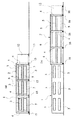
以下、本発明の可変建築物の具体的な実施形態を説明する。図1〜図4は第1実施形態を示すもので、図中符号1は本体部、2は可動フレームである。本体部1はそれ自体が独立して学校として機能する2階建ての建築物であり、その外壁には窓3が設けられ、内部には図示は省略しているが教室、職員室、放送室、保健室、給食室等の学校として本来的に必要な諸施設や諸設備が備えられている。また、可動フレーム2は柱4と梁5およびその全体を覆う屋根6を有する構造体であって、平常時には図1(a)、図2(a)、図3(a)に示すように本体部1を覆うようにその外側に設けられてそこに定置されているが、大災害発生時等には必要に応じて本体部1の側方に移動し得るように走行可能に設けられている。なお、可動フレーム2を移動させるための駆動源や駆動機構は適宜で良いが、いずれにしても災害発生時に支障なく移動可能なように自家発電設備等の非常用動力源を備えておく必要がある。
【0008】
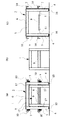
そして、大災害発生時等においては、図1(b)、図2(b)、図3(b)および(c)に示すように、可動フレーム2を本体部1の側方に移動させるとその内部には空間が確保されるから、図2(b)、図3(c)に示すように可動フレーム2に外壁7を取り付けるとともにその内部にスラブ8を設置することにより、可動フレーム2は本体部1に隣接する2階建ての仮設建築物となり、それを避難施設として使用し得るものとなっている。
【0009】
なお、図3(a)に示すように、上記のスラブ8は本体部1に設けた二重スラブ9内に引き出し可能に収納されており、また、上記外壁7は折り畳み可能とされてそれを折り畳んだ状態で収納しておく庇10が可動フレーム2に設けられている。したがって、可動フレーム2を移動させる際にはスラブ8が本体部1の二重スラブ9から自ずと引き出されるから、それを支持部材11により適宜支持することのみで速やかにスラブ8を設置することができ、かつ、折り畳んでおいた外壁7を引き降ろすことのみでその外壁7を速やかに取り付けることができ、これにより直ちに2階建ての避難施設を確保することができる。そして、そのようにして設けた避難施設内に床や間仕切を設けることにより、プライバシーを確保しかつある程度の避難生活レベルを確保することができる。
【0010】
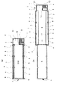
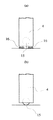
なお、図2に示すように可動フレーム2の一端側には共用部12が設けられてそこには外壁が設けられており、その内部には階段室13および倉庫14が設けられ、その階段室13は平常時においても本体部1の用に供され、倉庫14には避難施設において必要となる各種の資材たとえば間仕切パネル等を収納しておくと良い。また、図4に示すように可動フレーム2の柱4の脚部には車輪15を図示しない昇降機構により引き込み可能に組込んでおいて、可動フレーム2を移動させる際には(b)に示すように車輪15を引き出すようにし、かつ平常時および避難施設として使用する際には(a)に示すように車輪15を引き上げて積層ゴム等の免震装置16により支持して定置すれば良い。図3(a)に示す符号17は可動フレーム2の移動をガイドするためのガイドローラである。
【0011】
上記構成の可変建築物は、平常時はその全体が通常の学校として支障なく機能することはもとより、災害発生時等においては可動フレーム2を移動させてスラブ8および外壁7を設置することで多数の被災者を収納し得る避難施設として直ちに機能し得る。そして、その際にも本体部1は本来の学校としての機能をほぼそのまま維持できるし、本体部1に備えられている校内放送設備、保健室、給食室等の諸施設は避難施設に対してもそのまま有効に利用可能である。
【0012】
なお、上記第1実施形態の可変建築物の規模や平面形状は任意であり、たとえば図5に示すように全体として円弧状をなすものとして、その中央部に位置する円弧状の本体部1の両端部にそれぞれ円弧状の可動フレーム2,2を移動可能に設けておく等、適宜の形態が考えられる。また、平常時の用途としては学校とすることが最も好適であるが、たとえば公民館、集会場の類の他の用途の公共施設に対して適用することも可能である。
【0016】
以上で本発明の実施形態を説明したが、本発明の可変建築物を単なる避難施設としてのみならず、地域の防災拠点として機能させるべく以下に列挙するような機能を付加することがより好ましい。すなわち、本発明の可変建築物は十分な耐震性能を有するものとしてたとえば震度7に耐え得る免震設計を行うべきである。また、耐火性能も十分に考慮し、延焼防止対策として建物を敷地境界から十分に離して配置するとともに敷地周辺には防火帯を設ける。熱エネルギーとしては石油やガスの使用を避け全電化とすることが好ましい。自家発電設備は不可欠であるし、さらに太陽電池やソーラー発電設備を設置することが好ましい。非常時の水や食料を備蓄しておくための水槽や倉庫を十分に確保し、雨水やプール水を雑用水として利用したり、あるいは浄化設備により飲料水化して使用可能とすることが好ましい。また、水洗便所や排水設備が使用不能となることを考慮して便槽や浄化槽を備えることが好ましい。防災無線設備やネットワーク通信システム、非常時専用電話回線を確保しておく。グラウンドは緊急ヘリポートとして使用可能としておき、避難施設として使用可能な地下駐車場を設けておく。保健室には最低限度の医療設備や十分な量の医療品を確保しておく。
【0017】
さらに、上記実施形態はいずれも災害発生時に避難施設として使用するものとしたが、本発明の可変建築物は非常時に避難施設として使用することに限るものではなく、必要であれば平常時においてもその形態を自由に変更してたとえばセミナールームや展示場等の用途として使用することも可能である。
【0018】
【発明の効果】
本発明の可変建築物によれば、必要に応じてその用途や規模、形態を容易に変更できるものであり、たとえば災害発生時等には速やかに避難施設に転換することが可能である。特に、本体部を覆うように可動フレームを設けておき、その可動フレームを本体部の側方に移動させて外壁およびスラブを設けるように構成することにより、本体部をほぼそのまま本来の用途に使用しつつ可動フレームの内側をたとえば避難施設として使用することができる。その場合、本体部の用途を学校とすればそこに備えられている諸設備を他の用途にも有効に活用可能であって特に好適である。また、可動フレームに設置するべきスラブを本体部に引き出し可能に収納しておいたり、可動フレームを覆う外壁を折り畳んで庇に収納しておくことにより他の用途たとえば避難施設への転換をより速やかにかつ簡便に行うことができ、可動フレームを免震装置により支持して定置するとともにその移動の際には車輪を装着することで耐震性能を確保できるとともに移動を容易に行うことができる。
【図面の簡単な説明】
【図1】本発明の第1実施形態である可変建築物の立面図である。
【図2】同、平面図である。
【図3】同、各部の断面図である。
【図4】同、要部拡大図である。
【図5】第1実施形態の可変建築物の他の例を示す図である。
【符号の説明】
1 本体部
2 可動フレーム
7 外壁
8 スラブ
10 庇
15 車輪
16 免震装置[0001]
TECHNICAL FIELD OF THE INVENTION
The present invention relates to a variable building whose use, scale, and form can be easily changed, for example, a variable building that can be used as an evacuation facility during a disaster or the like while being used as a building for normal use in normal times.
[0002]
[Prior art]
In the event of a major disaster, evacuation facilities for accommodating many victims are secured each time, but evacuation shelters include various public facilities, especially elementary and junior high school buildings that are closely connected to the area. Often used. However, public facilities such as schools do not inherently function as shelters, and while these public facilities are used as shelters, the natural functions of the facilities are naturally sacrificed. For very long periods, problems arise.
[0003]
[Problems to be solved by the invention]
As in the case above, conventional buildings are not designed to change their use, scale, or form freely, nor are such things possible, and if it is possible, The development of effective means for tightening was desired.
[0004]
[Means for Solving the Problems]
According to the first aspect of the present invention, a movable frame that covers the main body and is movable sideways is provided outside the main body that functions as an independent building itself, and the movable frame is provided as necessary. By moving to the side of the main body to secure a space inside the movable frame and covering the movable frame with an outer wall and installing a slab inside the movable frame, the inside of the movable frame can be used , and the movable frame can be used. The movable wall is provided with an eave for making the outer wall covering the foldable and storing it in a folded state . According to a second aspect of the present invention, an internal space of the movable frame is used as an evacuation facility in the event of a disaster. The invention according to
[0007]
BEST MODE FOR CARRYING OUT THE INVENTION
Hereinafter, specific embodiments of the variable building of the present invention will be described. 1 to 4 show a first embodiment, wherein
[0008]
When a major disaster occurs, the
[0009]
As shown in FIG. 3A, the
[0010]
As shown in FIG. 2, a
[0011]
In the variable building having the above-described configuration, not only does the entire building function normally as a normal school without any trouble, but also, in the event of a disaster or the like, the
[0012]
The scale and plan shape of the variable building of the first embodiment are arbitrary. For example, as shown in FIG. 5, the variable building may be formed into an arc shape as a whole, and An appropriate form is conceivable, for example, in which arc-shaped
[0016]
Although the embodiment of the present invention has been described above, it is more preferable to add the functions listed below so that the variable building of the present invention can function not only as a mere evacuation facility but also as a regional disaster prevention base. That is, the variable building of the present invention should have a seismic isolation design capable of withstanding a
[0017]
Further, in each of the above-described embodiments, the variable building of the present invention is used as an evacuation facility in the event of a disaster, but it is not limited to using the variable building of the present invention as an evacuation facility in an emergency. The form can be freely changed and used, for example, for a seminar room or an exhibition hall.
[0018]
【The invention's effect】
ADVANTAGE OF THE INVENTION According to the variable building of this invention, the use, a scale, a form can be easily changed as needed, for example, when a disaster arises, etc., it is possible to switch to an evacuation facility immediately. In particular, a movable frame is provided so as to cover the main body, and the movable frame is moved to the side of the main body to provide an outer wall and a slab, so that the main body can be used as it is for its intended use. The inside of the movable frame can be used as an evacuation facility, for example. In this case, if the use of the main body is a school, various facilities provided therein can be effectively utilized for other uses, which is particularly preferable. Moreover, the slab should be placed on the movable frame or had been pulled out can be accommodated in the main body, faster conversion to other uses e.g. shelters by previously housed eaves fold the outer wall covering the movable frame In addition, the movable frame can be supported and fixed by the seismic isolation device, and at the time of the movement, the wheels can be mounted to secure the seismic performance and the movement can be easily performed.
[Brief description of the drawings]
FIG. 1 is an elevation view of a variable building according to a first embodiment of the present invention.
FIG. 2 is a plan view of the same.
FIG. 3 is a sectional view of each part.
FIG. 4 is an enlarged view of a main part of the same.
FIG. 5 is a diagram showing another example of the variable building of the first embodiment.
[Explanation of symbols]
DESCRIPTION OF
Claims (5)
Priority Applications (1)
| Application Number | Priority Date | Filing Date | Title |
|---|---|---|---|
| JP06155697A JP3552012B2 (en) | 1997-03-14 | 1997-03-14 | Variable buildings |
Applications Claiming Priority (1)
| Application Number | Priority Date | Filing Date | Title |
|---|---|---|---|
| JP06155697A JP3552012B2 (en) | 1997-03-14 | 1997-03-14 | Variable buildings |
Publications (2)
| Publication Number | Publication Date |
|---|---|
| JPH10252151A JPH10252151A (en) | 1998-09-22 |
| JP3552012B2 true JP3552012B2 (en) | 2004-08-11 |
Family
ID=13174511
Family Applications (1)
| Application Number | Title | Priority Date | Filing Date |
|---|---|---|---|
| JP06155697A Expired - Fee Related JP3552012B2 (en) | 1997-03-14 | 1997-03-14 | Variable buildings |
Country Status (1)
| Country | Link |
|---|---|
| JP (1) | JP3552012B2 (en) |
Families Citing this family (1)
| Publication number | Priority date | Publication date | Assignee | Title |
|---|---|---|---|---|
| JP6030427B2 (en) * | 2012-12-10 | 2016-11-24 | 鹿島建設株式会社 | A multipurpose facility that combines a show stage with sea lions and a concert stage |
-
1997
- 1997-03-14 JP JP06155697A patent/JP3552012B2/en not_active Expired - Fee Related
Also Published As
| Publication number | Publication date |
|---|---|
| JPH10252151A (en) | 1998-09-22 |
Similar Documents
| Publication | Publication Date | Title |
|---|---|---|
| US6981347B1 (en) | Modular emergency shelter system | |
| AU2007227250A1 (en) | Rapidly deployable modular building and methods | |
| KR101873707B1 (en) | Emergency relief house on the disaster | |
| US20180128038A1 (en) | Storm Shield for Bathing Structure | |
| JP3552012B2 (en) | Variable buildings | |
| JP6083775B1 (en) | Disaster evacuation equipment | |
| KR101923445B1 (en) | Structure for temporary residential | |
| JPWO2007063651A1 (en) | Temporary room | |
| JPH09125718A (en) | Simplified dwelling house | |
| KR20020005102A (en) | Folding container for compact housing | |
| JP3983262B1 (en) | Shed, restroom toilet kit | |
| RU2024699C1 (en) | Portable container home | |
| JP5308095B2 (en) | Storage box for disaster prevention | |
| JP2008025294A (en) | Shed used during disaster | |
| JP2006283405A (en) | Simple frame house | |
| US3908557A (en) | Mobile housing system | |
| JP2003239552A (en) | Simple toilet booth for emergency | |
| JP3562776B2 (en) | Foldable home module | |
| JPH11190149A (en) | Seismic isolation complex building | |
| JP5974138B1 (en) | building | |
| JP2017065672A (en) | Method for manufacturing levitation-type home care disaster prevention shelter | |
| JP2026017821A (en) | Disaster prevention temporary housing | |
| JP2014189964A (en) | Local disaster prevention warehouse | |
| JPH04136339A (en) | Stowage type simplified house | |
| JPH1193263A (en) | Simple dwelling |
Legal Events
| Date | Code | Title | Description |
|---|---|---|---|
| A977 | Report on retrieval |
Free format text: JAPANESE INTERMEDIATE CODE: A971007 Effective date: 20031128 |
|
| A131 | Notification of reasons for refusal |
Free format text: JAPANESE INTERMEDIATE CODE: A131 Effective date: 20031216 |
|
| A521 | Written amendment |
Free format text: JAPANESE INTERMEDIATE CODE: A523 Effective date: 20040205 |
|
| TRDD | Decision of grant or rejection written | ||
| A01 | Written decision to grant a patent or to grant a registration (utility model) |
Free format text: JAPANESE INTERMEDIATE CODE: A01 Effective date: 20040406 |
|
| A61 | First payment of annual fees (during grant procedure) |
Free format text: JAPANESE INTERMEDIATE CODE: A61 Effective date: 20040420 |
|
| R150 | Certificate of patent or registration of utility model |
Free format text: JAPANESE INTERMEDIATE CODE: R150 |
|
| LAPS | Cancellation because of no payment of annual fees |