JP3552573B2 - Control device for intake air volume of internal combustion engine - Google Patents
Control device for intake air volume of internal combustion engine Download PDFInfo
- Publication number
- JP3552573B2 JP3552573B2 JP06032799A JP6032799A JP3552573B2 JP 3552573 B2 JP3552573 B2 JP 3552573B2 JP 06032799 A JP06032799 A JP 06032799A JP 6032799 A JP6032799 A JP 6032799A JP 3552573 B2 JP3552573 B2 JP 3552573B2
- Authority
- JP
- Japan
- Prior art keywords
- engine
- internal combustion
- combustion engine
- fuel injection
- opening
- Prior art date
- Legal status (The legal status is an assumption and is not a legal conclusion. Google has not performed a legal analysis and makes no representation as to the accuracy of the status listed.)
- Expired - Fee Related
Links
Images





Classifications
-
- Y—GENERAL TAGGING OF NEW TECHNOLOGICAL DEVELOPMENTS; GENERAL TAGGING OF CROSS-SECTIONAL TECHNOLOGIES SPANNING OVER SEVERAL SECTIONS OF THE IPC; TECHNICAL SUBJECTS COVERED BY FORMER USPC CROSS-REFERENCE ART COLLECTIONS [XRACs] AND DIGESTS
- Y02—TECHNOLOGIES OR APPLICATIONS FOR MITIGATION OR ADAPTATION AGAINST CLIMATE CHANGE
- Y02T—CLIMATE CHANGE MITIGATION TECHNOLOGIES RELATED TO TRANSPORTATION
- Y02T10/00—Road transport of goods or passengers
- Y02T10/10—Internal combustion engine [ICE] based vehicles
- Y02T10/40—Engine management systems
Landscapes
- Control Of Throttle Valves Provided In The Intake System Or In The Exhaust System (AREA)
- Electrical Control Of Air Or Fuel Supplied To Internal-Combustion Engine (AREA)
Description
【0001】
【発明の属する技術分野】
本発明は内燃機関の吸気制御装置に関し、特に、アクセルペダルの踏込量とは独立に開度設定が行われる電子制御スロットル弁を備え、機関の始動時にこの電子制御スロットル弁の閉弁制御が行われる内燃機関の吸気制御装置に関する。
【0002】
【従来の技術】
近年、コンピュータの発達に伴い、内燃機関の回転数を電子的に最適に制御しようとする電子制御式の内燃機関が実用化されている。このような内燃機関の電子制御化としては、例えば、燃料噴射量制御、点火時期制御、吸排気弁の開弁時期の制御等が先行しており、これらに続いてスロットル弁の電子制御も実用段階に入っている。スロットル弁の開度を電子制御する内燃機関では、アクセルペダルの踏込量に関係なくスロットル弁の開度を設定することができる。
【0003】
このため、電子制御スロットル弁を使用して機関の始動時に吸気通路を閉じることにより、始動時の吸気量を減少させると共に、吸気管負圧を高めて燃料の気化促進を図ることが提案されている。これは、電子制御式の内燃機関では各燃焼室近傍の吸気通路内に燃料噴射弁が装着されているために、始動時に燃料が十分に微粒化しないことがあり、このときに始動性が悪化するのを防止するためである。
【0004】
このように機関の始動時に電子制御スロットル弁を閉じることにより、吸入空気量を減少させると共に、吸気管負圧を高めて燃料の気化促進性を図るものとしては、特開平9−324677号公報に開示のものがある。
一方、機関の始動初期には各気筒毎に最初だけは多量の燃料を噴射して機関がスムーズに始動するようにすることが行われる。これは始動噴射モードと呼ばれており、この後に通常の計算式で計算される燃料に切り換えられる。
【0005】
【発明が解決しようとする課題】
しかしながら、スロットル弁の閉弁制御が終了した後の気筒判別がされていない状態でスロットル弁を開く場合に、スロットル弁を開くタイミングが始動初期の始動噴射モード中に重なってしまうと、スロットル弁が開く前と開いた後の気筒では空燃比に大きな隔たりができてしまい、現在の気筒が不明であるために空燃比の補正が行えず、空燃比の気筒間差が大きくなって始動性に影響を与えるおそれがあるという問題点があった。
【0006】
そこで、本発明は、電子制御式の開閉弁が吸気通路に設けられた多気筒内燃機関であって機関の始動時に電子制御開閉弁の閉弁制御を行うものにおいて、電子制御開閉弁の閉弁制御中の開度変更制御の前後の内燃機関の空燃比が気筒間でばらつかないようにして、機関の始動性を向上させることができる内燃機関の吸気制御装置を提供することを目的としている。
【0007】
【課題を解決するための手段】
前記目的を達成する本発明の構成上の特徴は、以下に第1から第4の発明として示される。
第1の発明の構成上の特徴は、始動時に電子制御開閉弁を作動させて吸気通路を閉鎖する始動時の閉弁制御を行う内燃機関の吸気制御装置において、イグニッションスイッチがオンされた時に、電子制御開閉弁の開度を吸気通路との間に僅かな隙間を残すだけの全閉状態に近い第1の開度に制御する第1の開度制御手段と、開閉弁が第1の開度になった状態で機関のクランキングが行われた時に、燃料噴射弁からの燃料噴射回数を計数する燃料噴射回数計数手段と、噴射回数が機関の気筒数よりも少ない所定の回数に達したか否かを判定する噴射気筒数判定手段と、内燃機関のアイドル時のISC流量の学習値、大気圧、大気圧補正係数、内燃機関に搭載された補機の運転状態パラメータを読み込む運転状態パラメータの読み込み手段と、アイドル時のISC流量の学習値を、読み込んだ運転状態パラメータに基づいて補正して、内燃機関のISC流量を算出するISC流量の算出手段と、算出したISC流量を流す電子制御開閉弁の第2の開度を設定する第2の開度設定手段と、噴射回数が機関の気筒数よりも少ない所定の回数に達した時に、前記開閉弁の開度を前記第2の開度に制御する第2の開度制御手段と、開閉弁が第2の開度に制御された時に、燃料噴射弁からの燃料噴射量を増量補正する燃料噴射量の始動時補正手段とを設けたことにある。
【0008】
第1の発明によれば、機関の始動時に閉弁されている電子制御開閉弁を開弁する際に、開弁前に燃料が噴射された気筒数が分かると共に、燃料が噴射された気筒数が分かった時点において流れるISC流量が分かるので、これらの気筒に吸入された混合気の空燃比が分かり、開弁後の空燃比を燃料噴射量の調整で開弁前の気筒の空燃比に合わせることができるので始動性が向上する。
第2の発明の構成上の特徴は、第1の発明において、機関が偶数気筒の場合に、噴射回数が多気筒内燃機関の半分の気筒数と同数に達した時に、第2の開度制御手段が開閉弁の開度を第2の開度に制御することにある。
【0009】
第2の発明によれば、開閉弁を開くタイミングが多気筒内燃機関の気筒数の半分の気筒に燃料が噴射されたタイミングとなるので、開閉弁を開弁した後の燃料噴射量の補正が容易になる。
第3の発明の構成上の特徴は、第1または第2の発明において、第1の開度における開閉弁と吸気通路との隙間が、最小のアイドル空気流量値が確保できる隙間であることにある。
【0010】
第3の発明によれば、開閉弁の閉弁効果を損なうことなくスムーズな始動が可能になる。
第4の発明の構成上の特徴は、第1の発明から第3の発明のいずれかにおいて、第2の開度制御手段と燃料噴射量の始動時補正手段が、機関始動開始後の経過時間が所定時間を越えた時に動作を停止することにある。
【0011】
第4の発明によれば、機関始動時の閉弁制御から通常の制御にスムーズに切り換わることができる。
【0012】
【発明の実施の形態】
以下添付図面を用いて本発明の実施形態を具体的な実施例に基づいて詳細に説明する。
図1には本発明の一実施例の吸気制御装置を備えた電子制御燃料噴射式の多気筒内燃機関1が概略的に示されている。図1において、内燃機関1の吸気通路2には図示しないエアクリーナの下流側にスロットル弁3が設けられている。このスロットル弁3の軸の一端にはこのスロットル弁3を駆動するアクチュエータであるスロットルモータ4が設けられており、他端にはスロットル弁3の開度を検出するスロットル開度センサ5が設けられている。即ち、この実施例のスロットル弁3は、アクセルペダル14の開度をアクセル開度センサ15で検出し、その開度や機関に取り付けられた電子制御機器の各制御信号と合わせて後述するECU(エンジン・コントロール・ユニット)10で最適なスロットル開度を決定し、スロットルモータ4によって開閉駆動される電子制御スロットル(以後、単に電子スロットルと記す)に組み込まれたものである。電子スロットルでは、スロットル弁3の開度指令値がECU10から入力された時に、スロットルモータ4がこの指令値に応答してスロットル弁3を指令開度に追従させる。
【0013】
吸気通路2のスロットル弁3の上流側には大気圧センサ18があり、下流側にはサージタンク6がある。このサージタンク6内には吸気の圧力を検出する圧力センサ7が設けられている。更に、サージタンク6の下流側には、各気筒毎に燃料供給系から加圧燃料を吸気ポートへ供給するための燃料噴射弁8が設けられている。スロットル開度センサ5の出力と圧力センサ7の出力は、マイクロコンピュータを内蔵したECU10に入力される。
【0014】
また、内燃機関1のシリンダブロックの冷却水通路9には、冷却水の温度を検出するための水温センサ11が設けられている。水温センサ11は冷却水の温度に応じたアナログ電圧の電気信号を発生する。排気通路12には、排気ガス中の3つの有害成分HC,CO,NOxを同時に浄化する三元触媒コンバータ(図示せず)が設けられており、この触媒コンバータの上流側の排気通路12には、空燃比センサの一種であるO2 センサ13が設けられている。O2 センサ13は排気ガス中の酸素成分濃度に応じて電気信号を発生する。これら水温センサ11及びO2 センサ13の出力はECU10に入力される。
【0015】
更に、このECU10には、アクセル開度センサ15からのアクセルペダルの踏込量信号(アクセル開度信号)、バッテリ16に接続されたイグニッションスイッチ17からのキー位置信号(アクセサリ位置、オン位置、スタータ位置)、クランクシャフトの一端に取り付けられたクランクシャフトタイミングプーリと一体型のタイミングロータ24に近接して設けられたクランク位置センサ21からの上死点信号TDCや所定角度毎のクランク角信号CAや、油温センサ22からの潤滑油の温度が入力される。また、クランクシャフトの他端に設けられたリングギヤ23は機関1の始動時にスタータ19によって回転させられる。
【0016】
機関回転数Neは、所定クランク角信号CAの間隔(時間)を計測することにより得られる。タイミングロータ24には信号歯が設けられており、上死点の検出用に2枚の欠歯部を備えた34歯となっている。クランク位置センサ21は電磁ピックアップから構成することができ、10°毎のクランク回転信号を出力する。クランク位置センサ21は欠歯部の箇所の信号を検出することにより、正確な上死点を検出することができる。また、内燃機関の燃料噴射が実行される気筒は、このクランク位置センサ21からの信号と、図示しないカム位置センサからの信号により判別することができる。
【0017】
従来の内燃機関では、一般に直流直巻モータから構成されるスタータ19はイグニッションスイッチ17がスタータ位置にされた時にオンするスタータスイッチを介してバッテリ16に接続されている。従って、イグニッションスイッチ17がオンされ、その後にイグニッションスイッチ17がスタータ位置にされた時にスタータ19が起動されて機関1が起動する。そして、機関1が稼働を開始すると、ECU10が通電されてプログラムが起動し、各センサからの出力を取り込み、スロットル弁3を開閉するスロットルモータ4や燃料噴射弁8、或いはその他のアクチュエータを制御する。ECU10には、各種センサからのアナログ信号をディジタル信号に変換するA/D変換器が含まれ、各種センサからの入力ディジタル信号や各アクチュエータを駆動する信号が出入りする入出力インタフェース101、演算処理を行うCPU102、ROM103やRAM104等のメモリや、クロック105等が設けられており、これらはバス106で相互に接続されている。ECU10の構成については公知であるので、これ以上の説明を省略する。
【0018】
一方、この実施例では、スタータ19が直接バッテリ16に接続されておらず、スタータ駆動回路20を介してバッテリ16に接続されている。そして、このスタータ駆動回路20は、ECU10からのスタータ信号STが入力されないとスタータ19をバッテリ16に接続しないようになっている。
この実施例では、機関1の始動時にスロットル弁3を一時的に閉弁して吸気通路2をほぼ閉塞し、スロットル弁3の下流側に負圧を発生させて機関の始動性を向上させている。一方、機関1が停止している時には、スロットル弁3は全閉位置にはなく、僅かにあいている。従って、機関1が停止している状態では、スロットル弁3の吸気通路2内は大気圧になっている。
【0019】
従って、機関1を始動させる時には、スロットルモータ4を駆動してスロットル弁3を全閉位置に制御する必要がある。なお、ここでいうスロットル弁3の全閉位置3は、スロットル弁3と吸気通路2とが衝突した状態ではなく、僅かに隙間が開いている位置のことであり、この実施例では、この隙間は最小限の空気流量が流れる程度の隙間である。このため、ECU10には、前述のようにイグニッションスイッチ17からのキー位置信号とスロットル開度センサ5からのスロットル開度信号が入力されている。
【0020】
ここで、以上のように構成された機関1の始動時に、ECU10が実行するスロットル弁3の駆動制御の手順、および燃料の噴射制御について、その実施例を図2から図6のフローチャートを用いて説明する。
図2は電子制御スロットル弁3の閉制御を実行するフラグFTHVCの設定手順を示すフローチャートである。図2に示すルーチンは機関1の始動時にのみイニシャルルーチンにおいて所定時間毎、例えば、数ms毎に実行される。
【0021】
この制御では、まずステップ201において図1で説明した水温センサ11によって検出された機関水温THWを読み込む。続くステップ202では、この水温が所定温度A℃〜B℃の範囲にあるか否かを判定する。水温THWがこの範囲にない時にはステップ204に進み、スロットル弁閉制御実行フラグFTHVCを“0”にしてこのルーチンを終了する。一方、水温THWがこの範囲に入っている時にはステップ203に進み、スロットル弁閉制御実行フラグFTHVCを“1”にしてこのルーチンを終了する。このスロットル弁閉制御実行フラグFTHVCは“1”の時に、スロットル弁の閉弁制御が行われることを示す。
【0022】
なお、この実施例では、水温THWが極低温のA℃未満と、極高温のB℃を越えた温度においてはスロットル弁閉制御実行フラグFTHVCを“0”にして、スロットル弁閉制御を実行しないようにしているが、これは現時点における機関の始動性の信頼性を高めるためであり、コストをかけて制御精度を高めるようにすれば、始動時のスロットル弁閉制御は、機関の水温条件に無関係に実行することも可能である。
【0023】
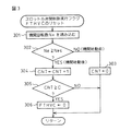
このようにして機関1の始動時に水温THWがA≦THW≦Bの範囲にある時に“1”に設定されるスロットル弁閉制御実行フラグFTHVCは、機関1が始動してから所定時間後にリセットされる。スロットル弁閉制御実行フラグFTHVCのリセット時間は、例えば、スロットル弁を閉弁した時のスロットル弁下流側の空気量が機関の始動後になくなる時間を考慮して設定することができる。この制御を図3に示すフローチャートを用いて説明する。図3に示すルーチンも機関1の始動時にのみイニシャルルーチンにおいて所定時間毎、例えば、数ms毎に実行される。
【0024】
この制御では、まず、ステップ301において機関回転数Neを読み込む。機関回転数Neは図1に示したクランク位置センサ21からのクランク位置信号から算出することができるものである。続くステップ302ではステップ301で読み込んだ機関回転数Neが設定回転数Nes以上か否か、例えば400rpm以上か否かを判定する。機関回転数Neが設定回転数Nes未満の時は、機関が未だ始動していないと判定してステップ303に進み、機関始動後経過時間カウンタCNTの値をクリアしてこのルーチンを終了する。
【0025】
一方、ステップ302において、機関回転数Neが設定回転数Nes以上の場合は機関が始動したと判定してステップ304に進み、始動後経過時間カウンタCNTの値を1だけインクリメントしてステップ305に進む。ステップ305では始動後経過時間カウンタCNTの値が所定時間を示す基準計数値Cに達したか否かを判定する。そして、始動後経過時間カウンタCNTの値が基準計数値Cに達していない時はこのままこのルーチンを終了し、始動後経過時間カウンタCNTの値が基準計数値Cに達した時はステップ306に進んでスロットル弁閉制御実行フラグFTHVCを“0”にしてこのルーチンを終了する。このようにして、機関の始動時に“1”になっていたスロットル弁閉制御実行フラグFTHVCは、機関が始動してから所定時間が経過すると“0”に設定される。
【0026】
図4は始動時に閉弁制御されたスロットル弁3の開度を、始動直後に設定し直すためのフラグFHSIJを設定するための手順を示すフローチャートである。この実施例では、フラグFHSIJは本発明が適用される多気筒内燃機関1の気筒数(偶数)の半分の気筒に対して燃料噴射が行われた時点で“1”に設定されるものとしている。従って、この実施例では、フラグFHSIJは半分の気筒の燃料噴射完了フラグを示すことになる。
【0027】
この半分の気筒の燃料噴射完了フラグFHSIJの設定においては、まず、ステップ401においてクランキング中か否かを判定する。そして、イグニッションスイッチ17はオンにされたが、まだスタータ位置にされていない場合、或いは、クランキングが終了した場合はステップ402に進む。ステップ402では後述する燃料噴射回数カウンタNの値をクリアすると共に、半分の気筒の燃料噴射完了フラグFHSIJもクリアしてこのルーチンを終了する。
【0028】
一方、ステップ401の判定がクランキング中の場合はステップ403に進み、ここで、燃料噴射弁8から燃料が噴射されたか否かを判定する。そして、燃料噴射が行われていない時にはこのルーチンを終了し、燃料噴射が行われた時にはステップ404に進む。ステップ404では半分の気筒の燃料噴射完了フラグFHSIJが“1”か否かを判定し、FHSIJが“1”の場合は既に機関の半分の気筒に対して燃料噴射が行われたと判定してこのルーチンを終了するが、FHSIJが“1”でない場合はステップ405に進む。
【0029】
ステップ405では燃料噴射が実行された回数を計数する燃料噴射回数カウンタNの値を1だけインクリメントしてステップ406に進む。ステップ406ではこの燃料噴射回数カウンタNの値が機関1の気筒の半分の数に達したか否かを判定する。そして、燃料噴射回数カウンタNの値が機関1の気筒の半分の数に達していない場合はこのルーチンを終了するが、燃料噴射回数カウンタNの値が機関1の気筒の半分の数に達した場合はステップ407に進んで半分の気筒の燃料噴射完了フラグFHSIJの値を“1”にしてこのルーチンを終了する。
【0030】
このようにして、この実施例では機関1のクランキング中に所定の気筒に燃料が噴射された回数が機関1の気筒数の半分に達した時に、半分の気筒の燃料噴射完了フラグFHSIJの値が“1”に設定される。
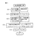
図5は機関1の始動時の電子制御スロットル弁3の開度設定の手順の一実施例を示すフローチャートである。図5に示すルーチンは所定時間毎、例えば、数ms毎に実行される。この実施例では、まず、ステップ501においてスロットル弁閉制御実行フラグFTHVCの値と半分の気筒の燃料噴射完了フラグFHSIJの値を読み込む。続くステップ502ではスロットル弁閉制御実行フラグFTHVCの値が“1”か否かを判定する。
【0031】
ステップ502でスロットル弁閉制御実行フラグFTHVCの値が“0”であると判定した場合は、機関1の始動が完了していると判定してステップ510に進む。ステップ510ではISC流量を通常の算出式によって計算し、続くステップ511ではステップ511で算出されたISC流量に応じたスロットル弁開度θthv をスロットル弁開度として設定し、ステップ512で後述する燃料噴射量補正係数Xの値を1にしてこのルーチンを終了する。機関の始動が完了している際の制御は本発明の主旨ではないので、これ以上の説明を省略する。
【0032】
一方、ステップ502においてスロットル弁閉制御実行フラグFTHVCの値が“1”であると判定した場合は、機関1の始動時であると判定してステップ503に進む。ステップ503ではステップ501で読み込んだ半分の気筒の燃料噴射完了フラグFHSIJの値が“1”であるか否かを判定する。そして、半分の気筒の燃料噴射完了フラグFHSIJの値が“0”の時はステップ504に進み、“1”の時はステップ506に進む。
【0033】
半分の気筒の燃料噴射完了フラグFHSIJの値が“0”の時、即ち、機関1の気筒数の半分の数の気筒に燃料噴射が未だ行われていない時には、ステップ504において、最小のISC流量ISCmin を流すスロットル弁開度θth1 をスロットル弁開度として設定し、ステップ505で後述する燃料噴射量補正係数Xの値を1にしてこのルーチンを終了する。このスロットル弁開度θth1 はスロットル弁3と吸気通路2とが接触しない程度の全閉に近い開度である。
【0034】
一方、ステップ503で気筒判別が終了したと判定した場合はステップ506に進み、ECU10のRAM104に格納されているアイドル時のISC流量の学習値ISCG、大気圧センサ18によって検出された大気圧AP、ECU10のROM103に格納されている大気圧補正係数AH、エアコン(空気調和装置)や電気負荷等の機関1に搭載された補機の運転状態パラメータを読み込む。続くステップ507では読み込んだアイドル時のISC流量の学習値ISCGを、大気圧AP、大気圧補正係数AH、補機の動作状態等の運転状態パラメータに基づいて補正してISC流量ISCHを算出する。
【0035】
次のステップ508ではステップ507で算出したISC流量ISCHを流すスロットル弁開度θth2 を設定し、続くステップ509で後述する燃料噴射量補正係数Xの値をZ(>0)にしてこのルーチンを終了する。
図6は以上説明した実施例における燃料噴射量の計算手順を示すフローチャートである。ステップ601では吸入空気量Qと機関回転数Neが読み込まれ、続くステップ602では基本噴射時間TPがKを定数として下式で計算される。
【0036】
TP = K×Q/Ne
そして、次のステップ603では、ECU10のROM103に記憶された始動増量補正係数S、暖機増量補正係数D、及び吸気温補正係数TMPAを読み込む。そして、ステップ604において始動時燃料噴射時間TAU*が次の式によって計算される。
【0037】
TAU* = TP×〔1+(1+TMPA+S)×(1+D)〕
この実施例では、以上のようにして算出された始動時燃料噴射時間TAU*に燃料噴射量補正係数Xをステップ605で乗算してこのルーチンを終了する。ステップ605で始動時燃料噴射時間TAU*に乗算する燃料噴射量補正係数Xは、図5のフローチャートで説明したように、機関1の始動時にスロットル弁閉制御実行フラグFTHVCの値が“0”の時と、スロットル弁閉制御実行フラグFTHVCの値は“1”で、かつ、半分の気筒の燃料噴射完了フラグFHSIJの値が“0”の時に1にされ、機関1の始動時にスロットル弁閉制御実行フラグFTHVCの値が“1”で、かつ、半分の気筒の燃料噴射完了フラグFHSIJの値が“1”の時に所定値Z(>0)にされる。
【0038】
これは、機関1の始動時にスロットル弁閉制御実行フラグFTHVCの値が“1”で、かつ、半分の気筒の燃料噴射完了フラグFHSIJの値が“1”の時に、機関の始動時の燃料噴射量TAU*が増量されることを示している。
図7は前述の実施例におけるスタータ信号ST、スロットル弁閉制御実行フラグFTHVC、半分の気筒の燃料噴射完了フラグFHSIJ、機関始動後カウンタCNT、機関回転数Ne、ISC流量、スロットル弁開度θth、及び、始動時燃料噴射量TAU*の補正係数Xの値の推移を示すタイムチャートである。
【0039】
スロットル弁閉制御実行フラグFTHVCが“1”の状態の時に、時刻T0でスタータ信号の値が1になって機関が始動状態となると、この時点では半分の気筒の燃料噴射完了フラグFHSIJは“0”であるので、スロットル弁開度θthは第1の開度θth1 に設定される。その後、時刻T1までのクランキング中は、スロットル弁3が略全閉の開度θth1 のまま必要最小限のISC流量ISCmin が流れる。
【0040】
機関のクランキング中に燃料噴射が行われ、その回数が時刻T1において内燃機関1の気筒数の半分に達すると、半分の気筒の燃料噴射完了フラグFHSIJが“1”なり、アイドル時のISC流量の学習値ISCGがRAM104から読み出されて機関の運転状態パラメータで補正されてISC流量ISCHが計算される。そして、このISC流量ISCHを流すためにスロットル弁3の開度θthが開度θth2 に設定されると共に、始動時燃料噴射量TAU*の補正係数Xの値が所定値Zに設定されて燃料噴射量の増量が行われる。その後、所定時間クランキングが続行された後に機関の回転数Neが次第に増大し始める。この後の時刻T2において機関回転数Neが所定回転数Nesに達すると、機関始動後カウンタCNTがカウントを開始する。この状態ではスロットル弁3が略全閉の開度θth2 のままISC流量ISCHが流れる。
【0041】
この後、時刻T3において機関始動後カウンタCNTが所定値Cに達すると、スロットル弁閉制御実行フラグFTHVCが“0”にされ、ISC流量は通常の算出式で計算され、スロットル弁開度θthは、算出された通常のISC流量に応じたスロットル弁開度θthv に設定される。また、この時、始動時燃料噴射量TAU*の補正係数Xの値が1に設定されて燃料噴射量の増量が終了する。
【0042】
このように、本発明では実施例において説明したように、機関の始動時にスロットル弁の閉弁制御を行う多気筒内燃機関において、始動クランキング中に燃料噴射が行われた気筒数を計数し、燃料噴射が行われた気筒数が多気筒内燃機関の半分の気筒に達した時に、略全閉状態のスロットル弁を僅かに開いて吸気量を増大させると共に、増大した吸気量に応じて燃料噴射量を増大する。これより、多気筒内燃機関の始動時の気筒間の空燃比のばらつきを抑えることができるので、始動性を良好にすることができる。
【0043】
なお、以上説明した実施例では、燃料噴射が行われた気筒数が多気筒内燃機関の半分の気筒に達した時に、スロットル弁を僅かに開いて吸気量を増大させると共に、増大した吸気量に応じて燃料噴射量を増大することによって多気筒内燃機関の始動時の気筒間の空燃比のばらつきを抑える制御について説明したが、この制御を実行する際の燃料噴射が行われた気筒数の判定は多気筒内燃機関の半分の気筒でなくても良い。例えば、8気筒内燃機関であれば、3気筒、或いは5気筒への燃料噴射が終了した時点でスロットル弁を僅かに開いて吸気量を増大させると共に、増大した吸気量に応じて燃料噴射量を増大するようにしても良い。
【0044】
また、以上説明した実施例では、内燃機関の吸気通路の閉鎖を電子制御スロットル弁3により行うものについて説明を行ったが、電子制御スロットル弁3の代わりに、電子制御される吸気制御弁が吸気通路に別に設けられているものについても本発明を有効に適用することができる。
【0045】
【発明の効果】
以上説明したように、本発明の内燃機関の吸気制御装置によれば、電子制御式の開閉弁が吸気通路に設けられた多気筒内燃機関であって機関の始動時に電子制御開閉弁の閉弁制御を行うものにおいて、機関の始動時に閉弁されている電子制御開閉弁を開弁する際に、開弁前に燃料が噴射された気筒数が分かると共に、燃料が噴射された気筒数が分かった時点において流れるISC流量が分かるので、電子制御開閉弁の閉弁制御中の開度変更制御の前後の内燃機関の空燃比が気筒間でばらつかないようにすることができ、機関の始動性を向上させることができるという効果がある。
【図面の簡単な説明】
【図1】本発明の一実施例の吸気制御装置が搭載された電子制御式多気筒内燃機関の構成を示す構成図である。
【図2】スロットル弁の閉制御を実行するフラグの設定手順を示すフローチャートである。
【図3】スロットル弁の閉制御を実行するフラグのリセットを示すフローチャートである。
【図4】多気筒内燃機関の所定数の気筒の燃料噴射完了フラグの設定手順を示すフローチャートである。
【図5】本発明の始動時の電子制御スロットル弁の開度設定の手順の一実施例を示すフローチャートである。
【図6】本発明の始動時の燃料噴射量の計算手順を示すフローチャートである。
【図7】本発明の実施例におけるスタータ信号、スロットル弁閉制御実行フラグ、半分の気筒への燃料噴射完了フラグ、機関始動開始後カウンタ、機関回転数、ISC流量、スロットル弁開度、及び、始動時燃料噴射量の補正計数の推移を示すタイムチャートである。
【符号の説明】
2…吸気通路
3…スロットル弁
4…スロットルモータ
5…スロットル開度センサ
8…燃料噴射弁
10…ECU
17…イグニッションスイッチ
18…大気圧センサ
19…スタータ
20…スタータ駆動回路
21…クランク位置センサ
23…リングギヤ
24…タイミングロータ[0001]
TECHNICAL FIELD OF THE INVENTION
The present invention relates to an intake control device for an internal combustion engine, and more particularly, to an intake control device provided with an electronically controlled throttle valve whose opening degree is set independently of the amount of depression of an accelerator pedal, and controls the closing of the electronically controlled throttle valve when the engine is started. The present invention relates to an intake control device for an internal combustion engine.
[0002]
[Prior art]
In recent years, with the development of computers, electronically controlled internal combustion engines that attempt to electronically optimally control the rotation speed of the internal combustion engine have been put to practical use. As electronic control of such internal combustion engines, for example, fuel injection amount control, ignition timing control, control of the opening timing of intake and exhaust valves, and the like have been preceded. You are in the stage. In an internal combustion engine that electronically controls the opening of the throttle valve, the opening of the throttle valve can be set regardless of the amount of depression of the accelerator pedal.
[0003]
For this reason, it has been proposed to use an electronically controlled throttle valve to close the intake passage when the engine is started, thereby reducing the amount of intake air at the start and increasing the intake pipe negative pressure to promote the vaporization of fuel. I have. This is because, in an electronically controlled internal combustion engine, fuel is not sufficiently atomized at the time of startup because the fuel injection valve is mounted in the intake passage near each combustion chamber, and the startability is deteriorated at this time. This is to prevent the user from doing so.
[0004]
Japanese Patent Application Laid-Open No. Hei 9-324677 discloses a technique in which the electronic control throttle valve is closed when the engine is started to reduce the amount of intake air and increase the negative pressure of the intake pipe to promote the fuel vaporization. Some are disclosed.
On the other hand, in the early stage of the start of the engine, a large amount of fuel is injected for each cylinder only at the beginning so that the engine can be started smoothly. This is called a start-up injection mode, after which the fuel is switched to the fuel calculated by the normal formula.
[0005]
[Problems to be solved by the invention]
However, when the throttle valve is opened in a state where the cylinder discrimination has not been performed after the closing control of the throttle valve has been completed and the timing of opening the throttle valve overlaps during the start-up injection mode at the initial stage of the start-up, the throttle valve is opened. There is a large gap in the air-fuel ratio between the cylinders before and after opening, and it is not possible to correct the air-fuel ratio because the current cylinder is unknown, and the difference in the air-fuel ratio between cylinders increases, affecting startability. There is a problem that there is a possibility of giving.
[0006]
Therefore, the present invention relates to a multi-cylinder internal combustion engine in which an electronically controlled on-off valve is provided in an intake passage and performs closing control of the electronically controlled on-off valve when the engine is started. It is an object of the present invention to provide an intake control device for an internal combustion engine that can improve the startability of the engine by preventing the air-fuel ratio of the internal combustion engine from varying between cylinders before and after opening degree change control during control. .
[0007]
[Means for Solving the Problems]
The structural features of the present invention that achieve the above object are shown below as first to fourth inventions.
According to a first aspect of the present invention, there is provided an intake control device for an internal combustion engine that performs a valve closing control at a start time by activating an electronic control on / off valve at a start to close an intake passage when the ignition switch is turned on. First opening control means for controlling the opening of the electronically controlled on-off valve to a first opening close to a fully closed state where only a slight gap is left between the electronically controlled on-off valve and the first on-off valve; When the cranking of the engine is performed in the state where the temperature has reached the predetermined value, the fuel injection number counting means for counting the number of fuel injections from the fuel injection valve, and the number of injections has reached a predetermined number smaller than the number of cylinders of the engine Means for judging whether or not the number of injection cylinders is determined, and an operating state parameter for reading a learning value of an ISC flow rate when the internal combustion engine is idling, an atmospheric pressure, an atmospheric pressure correction coefficient, and an operating state parameter of an auxiliary device mounted on the internal combustion engine. Means for calculating the ISC flow rate of the internal combustion engine by correcting the learning value of the ISC flow rate at the time of idling based on the read operating state parameter; and electronic control for flowing the calculated ISC flow rate. A second opening setting means for setting a second opening of the on-off valve, and the number of injections reaches a predetermined number smaller than the number of cylinders of the engine. Sometimes the on-off valve Opening degree Second opening degree control means for controlling the opening degree of the fuel injection valve to a second opening degree, and fuel injection amount starting time correction means for increasing and correcting the fuel injection amount from the fuel injection valve when the on-off valve is controlled to the second opening degree. And has been provided.
[0008]
According to the first aspect, when opening the electronically controlled on-off valve that is closed when the engine is started, the number of cylinders into which fuel has been injected before the valve is opened can be determined. At the same time, the ISC flow rate at the time when the number of cylinders into which fuel has been injected is known is known. Because , The air-fuel ratio of the air-fuel mixture sucked into these cylinders is known, and the air-fuel ratio after valve opening can be adjusted to the air-fuel ratio of the cylinder before valve opening by adjusting the fuel injection amount, so that the startability is improved.
A structural feature of the second invention is that, in the first invention, when the number of injections reaches the same number as half the number of cylinders of the multi-cylinder internal combustion engine when the engine is an even cylinder, the second opening degree control is performed. The means controls the opening of the on-off valve to the second opening.
[0009]
According to the second aspect, the timing at which the on-off valve is opened is the timing at which fuel is injected into half the number of cylinders of the multi-cylinder internal combustion engine. Therefore, the correction of the fuel injection amount after the on-off valve is opened can be made. It will be easier.
A structural feature of the third invention is that, in the first or second invention, a gap between the on-off valve and the intake passage at the first opening is a gap that can secure a minimum idle air flow value. is there.
[0010]
According to the third invention, a smooth start can be performed without impairing the valve closing effect of the on-off valve.
According to a fourth aspect of the present invention, in any one of the first to third aspects of the present invention, the second opening control means and the fuel injection amount start-time correction means are configured to determine the elapsed time since the start of the engine. Is to stop the operation when a predetermined time is exceeded.
[0011]
According to the fourth aspect, it is possible to smoothly switch from the valve closing control at the time of engine start to the normal control.
[0012]
BEST MODE FOR CARRYING OUT THE INVENTION
Hereinafter, embodiments of the present invention will be described in detail with reference to the accompanying drawings based on specific examples.
FIG. 1 schematically shows an electronically controlled fuel injection type multi-cylinder
[0013]
An
[0014]
Further, a water temperature sensor 11 for detecting the temperature of the cooling water is provided in the cooling water passage 9 of the cylinder block of the
[0015]
The
[0016]
The engine speed Ne is obtained by measuring the interval (time) of the predetermined crank angle signal CA. The
[0017]
In a conventional internal combustion engine, a
[0018]
On the other hand, in this embodiment, the
In this embodiment, when the
[0019]
Therefore, when starting the
[0020]
Here, the procedure of the drive control of the throttle valve 3 and the fuel injection control executed by the
FIG. 2 is a flowchart showing a procedure for setting a flag FTHVC for executing the closing control of the electronic control throttle valve 3. The routine shown in FIG. 2 is executed every predetermined time, for example, every several ms in the initial routine only when the
[0021]
In this control, first, in step 201, the engine water temperature THW detected by the water temperature sensor 11 described with reference to FIG. 1 is read. In the
[0022]
In this embodiment, the throttle valve closing control execution flag FTHVC is set to "0" and the throttle valve closing control is not executed when the water temperature THW is lower than the extremely low temperature of A.degree. This is to increase the reliability of the engine's startability at the present time.If the control accuracy is increased by increasing the cost, the throttle valve closing control at the time of the start will be affected by the water temperature condition of the engine. It can also be performed independently.
[0023]
In this way, the throttle valve closing control execution flag FTHVC that is set to “1” when the water temperature THW is in the range of A ≦ THW ≦ B when the
[0024]
In this control, first, at step 301, the engine speed Ne is read. The engine speed Ne can be calculated from the crank position signal from the
[0025]
On the other hand, if the engine speed Ne is equal to or higher than the set speed Nes in
[0026]
FIG. 4 is a flowchart showing a procedure for setting a flag FHSIJ for resetting the opening of the throttle valve 3 that has been controlled to be closed at the time of starting immediately after the starting. In this embodiment, the flag FHSIJ is set to “1” when fuel injection is performed on half of the number of cylinders (even number) of the multi-cylinder
[0027]
In setting the fuel injection completion flag FHSIJ for this half cylinder, it is first determined in
[0028]
On the other hand, if the determination in
[0029]
In
[0030]
In this way, in this embodiment, when the number of times that fuel is injected into a predetermined cylinder during cranking of the
FIG. 5 is a flowchart showing an embodiment of a procedure for setting the opening of the electronically controlled throttle valve 3 when the
[0031]
If it is determined in
[0032]
On the other hand, if it is determined in
[0033]
When the value of the fuel injection completion flag FHSIJ of half the cylinders is "0", that is, when fuel injection has not yet been performed on half the number of cylinders of the
[0034]
On the other hand, if it is determined in
[0035]
In the next step 508, the throttle valve opening θth2 for flowing the ISC flow rate ISCH calculated in
FIG. 6 is a flowchart showing a calculation procedure of the fuel injection amount in the embodiment described above. In
[0036]
TP = K × Q / Ne
Then, in the
[0037]
TAU * = TP × [1+ (1 + TMPA + S) × (1 + D)]
In this embodiment, the fuel injection amount correction coefficient X is multiplied by the fuel injection amount correction coefficient X at
[0038]
This is because when the value of the throttle valve closing control execution flag FTHVC is "1" at the time of starting the
FIG. 7 shows a starter signal ST, a throttle valve closing control execution flag FTHVC, a fuel injection completion flag FHSIJ of a half cylinder, a counter CNT after engine start, an engine speed Ne, an ISC flow rate, a throttle valve opening θth, 6 is a time chart showing a change in a value of a correction coefficient X of the starting fuel injection amount TAU *.
[0039]
When the value of the starter signal becomes 1 and the engine is started at time T0 when the throttle valve closing control execution flag FTHVC is "1", the fuel injection completion flag FHSIJ of half the cylinders is set to "0" at this time. Therefore, the throttle valve opening θth is set to the first opening θth1. Thereafter, during cranking until time T1, the minimum necessary ISC flow ISCmin flows while the throttle valve 3 remains at the fully closed opening θth1.
[0040]
When fuel injection is performed during cranking of the engine and the number of times reaches half of the number of cylinders of the
[0041]
Thereafter, when the post-engine start counter CNT reaches a predetermined value C at time T3, the throttle valve closing control execution flag FTHVC is set to "0", the ISC flow rate is calculated by a normal calculation formula, and the throttle valve opening degree θth is , The throttle valve opening θthv is set according to the calculated normal ISC flow rate. At this time, the value of the correction coefficient X of the starting fuel injection amount TAU * is set to 1, and the increase of the fuel injection amount ends.
[0042]
As described above, in the present invention, as described in the embodiment, in the multi-cylinder internal combustion engine that performs the closing control of the throttle valve at the time of starting the engine, the number of cylinders in which the fuel injection is performed during the starting cranking is counted. When the number of cylinders in which fuel injection has been performed reaches half of the number of cylinders of the multi-cylinder internal combustion engine, the throttle valve in a substantially fully closed state is slightly opened to increase the amount of intake air, and fuel injection is performed according to the increased amount of intake air. Increase volume. As a result, variation in the air-fuel ratio between the cylinders at the time of starting the multi-cylinder internal combustion engine can be suppressed, so that the startability can be improved.
[0043]
In the embodiment described above, when the number of cylinders in which fuel injection has been performed reaches half the number of cylinders of the multi-cylinder internal combustion engine, the throttle valve is slightly opened to increase the intake air amount, and The control for suppressing the variation in the air-fuel ratio between the cylinders at the time of starting the multi-cylinder internal combustion engine by increasing the fuel injection amount accordingly has been described. However, when executing this control, the determination of the number of the cylinders on which the fuel injection has been performed is determined. May not be half the cylinder of the multi-cylinder internal combustion engine. For example, in the case of an eight-cylinder internal combustion engine, when the fuel injection into three or five cylinders is completed, the throttle valve is slightly opened to increase the intake air amount, and the fuel injection amount is increased in accordance with the increased intake air amount. You may make it increase.
[0044]
Further, in the above-described embodiment, the electronic control throttle valve 3 is used to close the intake passage of the internal combustion engine. However, instead of the electronic control throttle valve 3, an electronically controlled intake control valve is used. The present invention can be effectively applied to a device provided separately in a passage.
[0045]
【The invention's effect】
As described above, according to the intake control apparatus for an internal combustion engine of the present invention, the electronically controlled on-off valve is a multi-cylinder internal combustion engine provided in the intake passage, and the electronically controlled on-off valve is closed when the engine is started. In the control, When opening an electronically controlled on-off valve that is closed when the engine is started, the number of cylinders to which fuel has been injected before the valve is opened and the ISC flow rate at the time when the number of cylinders to which fuel has been injected are known So you can see The air-fuel ratio of the internal combustion engine before and after the opening change control during the valve closing control of the electronic control on-off valve can be prevented from varying between the cylinders, and there is an effect that the startability of the engine can be improved. .
[Brief description of the drawings]
FIG. 1 is a configuration diagram showing a configuration of an electronically controlled multi-cylinder internal combustion engine equipped with an intake control device according to one embodiment of the present invention.
FIG. 2 is a flowchart showing a procedure for setting a flag for executing a throttle valve closing control.
FIG. 3 is a flowchart showing resetting of a flag for executing a throttle valve closing control.
FIG. 4 is a flowchart showing a procedure for setting a fuel injection completion flag for a predetermined number of cylinders of a multi-cylinder internal combustion engine.
FIG. 5 is a flowchart showing an embodiment of a procedure for setting an opening degree of an electronically controlled throttle valve at the time of starting according to the present invention.
FIG. 6 is a flowchart showing a procedure for calculating a fuel injection amount at the time of starting according to the present invention.
FIG. 7 shows a starter signal, a throttle valve closing control execution flag, a fuel injection completion flag for half a cylinder, a counter after engine start, an engine speed, an ISC flow rate, a throttle valve opening, and a throttle valve in the embodiment of the present invention. 6 is a time chart showing a transition of a correction count of a fuel injection amount at the time of starting.
[Explanation of symbols]
2. Intake passage
3. Throttle valve
4 ... Throttle motor
5 Throttle opening sensor
8. Fuel injection valve
10 ... ECU
17 ... Ignition switch
18. Atmospheric pressure sensor
19 ... Starter
20 Starter drive circuit
21 ... Crank position sensor
23 ... Ring gear
24 ... Timing rotor
Claims (4)
イグニッションスイッチがオンされた時に、前記電子制御開閉弁の開度を前記吸気通路との間に僅かな隙間を残すだけの全閉状態に近い第1の開度に制御する第1の開度制御手段と、
前記開閉弁が前記第1の開度になった状態で前記機関のクランキングが行われた時に、燃料噴射弁からの燃料噴射回数を計数する燃料噴射回数計数手段と、
前記噴射回数が前記機関の気筒数よりも少ない所定の回数に達したか否かを判定する噴射気筒数判定手段と、
前記内燃機関のアイドル時のISC流量の学習値、大気圧、大気圧補正係数、前記内燃機関に搭載された補機の運転状態パラメータを読み込む運転状態パラメータの読み込み手段と、
前記アイドル時のISC流量の学習値を、読み込んだ前記運転状態パラメータに基づいて補正して、前記内燃機関のISC流量を算出するISC流量の算出手段と、
算出したISC流量を流す前記電子制御開閉弁の第2の開度を設定する第2の開度設定手段と、
前記噴射回数が前記機関の気筒数よりも少ない所定の回数に達した時に、前記開閉弁の開度を前記第2の開度に制御する第2の開度制御手段と、
前記開閉弁が前記第2の開度に制御された時に、前記燃料噴射弁からの燃料噴射量を増量補正する燃料噴射量の始動時補正手段と、を備えることを特徴とする内燃機関の吸入空気量の制御装置。An intake control device for an internal combustion engine that performs a valve closing control at the time of starting by closing an intake passage by operating an electronic control on-off valve at the time of starting,
A first opening degree control for controlling an opening degree of the electronic control on / off valve to a first opening degree close to a fully-closed state where only a slight gap is left between the electronic control on-off valve and the intake passage when an ignition switch is turned on; Means,
When cranking of the engine is performed in a state where the on-off valve is at the first opening degree, a fuel injection number counting means for counting the number of fuel injections from the fuel injection valve,
Injection cylinder number determining means for determining whether the number of injections has reached a predetermined number less than the number of cylinders of the engine ,
Operating state parameter reading means for reading a learning value of an ISC flow rate at the time of idling of the internal combustion engine, an atmospheric pressure, an atmospheric pressure correction coefficient, and an operating state parameter of an auxiliary device mounted on the internal combustion engine;
ISC flow rate calculating means for correcting the learning value of the ISC flow rate at the time of idling based on the read operating state parameter to calculate the ISC flow rate of the internal combustion engine;
Second opening setting means for setting a second opening of the electronically controlled on-off valve for flowing the calculated ISC flow rate;
Sometimes the injection number reaches a predetermined number of times less than the number of cylinders of the engine, a second opening control means for controlling the opening of the on-off valve to the second opening,
A fuel injection amount starting correction means for increasing and correcting the fuel injection amount from the fuel injection valve when the on-off valve is controlled to the second opening degree. Air volume control device.
Priority Applications (1)
| Application Number | Priority Date | Filing Date | Title |
|---|---|---|---|
| JP06032799A JP3552573B2 (en) | 1999-03-08 | 1999-03-08 | Control device for intake air volume of internal combustion engine |
Applications Claiming Priority (1)
| Application Number | Priority Date | Filing Date | Title |
|---|---|---|---|
| JP06032799A JP3552573B2 (en) | 1999-03-08 | 1999-03-08 | Control device for intake air volume of internal combustion engine |
Publications (2)
| Publication Number | Publication Date |
|---|---|
| JP2000257480A JP2000257480A (en) | 2000-09-19 |
| JP3552573B2 true JP3552573B2 (en) | 2004-08-11 |
Family
ID=13138977
Family Applications (1)
| Application Number | Title | Priority Date | Filing Date |
|---|---|---|---|
| JP06032799A Expired - Fee Related JP3552573B2 (en) | 1999-03-08 | 1999-03-08 | Control device for intake air volume of internal combustion engine |
Country Status (1)
| Country | Link |
|---|---|
| JP (1) | JP3552573B2 (en) |
Cited By (1)
| Publication number | Priority date | Publication date | Assignee | Title |
|---|---|---|---|---|
| WO2006038306A1 (en) * | 2004-10-01 | 2006-04-13 | Toyota Jidosha Kabushiki Kaisha | Device and method for controlling internal combustion engine |
Families Citing this family (2)
| Publication number | Priority date | Publication date | Assignee | Title |
|---|---|---|---|---|
| JP2009007993A (en) * | 2007-06-27 | 2009-01-15 | Toyota Motor Corp | Start control device for internal combustion engine |
| WO2017188144A1 (en) * | 2016-04-25 | 2017-11-02 | ヤマハ発動機株式会社 | Engine control device |
-
1999
- 1999-03-08 JP JP06032799A patent/JP3552573B2/en not_active Expired - Fee Related
Cited By (3)
| Publication number | Priority date | Publication date | Assignee | Title |
|---|---|---|---|---|
| WO2006038306A1 (en) * | 2004-10-01 | 2006-04-13 | Toyota Jidosha Kabushiki Kaisha | Device and method for controlling internal combustion engine |
| CN101031710B (en) * | 2004-10-01 | 2010-05-05 | 丰田自动车株式会社 | Internal combustion engine control device and internal combustion engine control method |
| US8176727B2 (en) | 2004-10-01 | 2012-05-15 | Toyota Jidosha Kabushiki Kaisha | Internal combustion engine control apparatus and control method of internal combustion engine |
Also Published As
| Publication number | Publication date |
|---|---|
| JP2000257480A (en) | 2000-09-19 |
Similar Documents
| Publication | Publication Date | Title |
|---|---|---|
| EP1079089A2 (en) | Control apparatus for internal combustion engine and method of controlling internal combustion engine | |
| JPH0211729B2 (en) | ||
| JP3506042B2 (en) | Control device for internal combustion engine | |
| JP3758235B2 (en) | Intake control device for internal combustion engine | |
| JP3675035B2 (en) | Fuel injection amount control device for internal combustion engine | |
| JP3552575B2 (en) | Intake control device for internal combustion engine | |
| JP3552573B2 (en) | Control device for intake air volume of internal combustion engine | |
| JP3436173B2 (en) | Intake control device for internal combustion engine | |
| JP2000291467A (en) | Control device for internal combustion engine | |
| JP2000130221A (en) | Fuel injection control device for internal combustion engine | |
| JP3598863B2 (en) | Intake control device for internal combustion engine | |
| JP3496575B2 (en) | Internal combustion engine speed control device | |
| JP4160745B2 (en) | Control method for internal combustion engine | |
| JP2004197693A (en) | Air-fuel ratio control device for internal combustion engine | |
| JP3478170B2 (en) | Idle speed control device for internal combustion engine | |
| JP3715109B2 (en) | Fuel injection control method for internal combustion engine | |
| JP3601209B2 (en) | Failure diagnosis device for intake control device of internal combustion engine | |
| JP3613662B2 (en) | Intake control device for internal combustion engine | |
| JP3559164B2 (en) | Atmospheric pressure correction advance angle control method for internal combustion engine | |
| JPH0748992Y2 (en) | Engine fuel controller | |
| JP2512073Y2 (en) | Engine fuel injection control device | |
| JPH05312068A (en) | Fuel injection control device at startup | |
| JP3632680B2 (en) | Fuel supply control device for internal combustion engine | |
| JP2005054600A (en) | Start control device for internal combustion engine | |
| JP2004183502A (en) | Engine fuel injection control device |
Legal Events
| Date | Code | Title | Description |
|---|---|---|---|
| TRDD | Decision of grant or rejection written | ||
| A01 | Written decision to grant a patent or to grant a registration (utility model) |
Free format text: JAPANESE INTERMEDIATE CODE: A01 Effective date: 20040413 |
|
| A61 | First payment of annual fees (during grant procedure) |
Free format text: JAPANESE INTERMEDIATE CODE: A61 Effective date: 20040426 |
|
| R150 | Certificate of patent or registration of utility model |
Free format text: JAPANESE INTERMEDIATE CODE: R150 |
|
| FPAY | Renewal fee payment (event date is renewal date of database) |
Free format text: PAYMENT UNTIL: 20080514 Year of fee payment: 4 |
|
| FPAY | Renewal fee payment (event date is renewal date of database) |
Free format text: PAYMENT UNTIL: 20090514 Year of fee payment: 5 |
|
| FPAY | Renewal fee payment (event date is renewal date of database) |
Free format text: PAYMENT UNTIL: 20100514 Year of fee payment: 6 |
|
| FPAY | Renewal fee payment (event date is renewal date of database) |
Free format text: PAYMENT UNTIL: 20110514 Year of fee payment: 7 |
|
| FPAY | Renewal fee payment (event date is renewal date of database) |
Free format text: PAYMENT UNTIL: 20110514 Year of fee payment: 7 |
|
| FPAY | Renewal fee payment (event date is renewal date of database) |
Free format text: PAYMENT UNTIL: 20120514 Year of fee payment: 8 |
|
| LAPS | Cancellation because of no payment of annual fees |