【0001】
【産業上の利用分野】
本発明は、隅棟を有する建築物の屋根の隅木、谷木の組み立てに使用する接合金具並びに当該金具を使用した組立工法に関するものである。
【0002】
【従来の技術及び発明が解決しようとする課題】
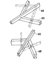
従来の木造軸組工法における隅屋根の骨組みとなる隅木や谷木の組み込みは、図8に例示するように、隅木01や谷木02と、これらの支持部材である軒桁、母屋または棟木など桁材(横架材)03との接合部分は、両部材に切欠き加工を行って、これを組み合わせていた。しかし切欠き加工の寸法決定、実施作業には熟練技術と多大な労力が必要とされ、両部材に断面欠損が生じる等の問題点を有している。而も隅木01や谷木02によって支持される屋根面材と、桁材03との間に間隙が生ずる構造は、建築物への断熱機能付与に不利益なものとなる。
【0003】
そこで隅木01や谷木02によって支持される屋根面材と、軒桁(桁材)03との間に隙間が生じないようにし、且つ部材の切欠き加工を省略できる工法が提案されている。
【0004】
例えば特開平09−302832号公報並びに09−302833号公報には、束木の側面に固定して、左右隅木の継手板部を備えた金具が開示されているが、前記金具は、一面の固定部で2個以上の隅木を連結するもので強度上の不安があり、強度の信頼性を高めるために、束木への金具固定をボルトとして、束木と棟木との連結構造を複雑にしている。
【0005】
また前記公報には、軒桁に隅木を連結する金具も開示されている。この金具は、軒桁の上面並びに入隅側の火打ち梁上に固定する固定板に、隅木を連結する縦板状の継手板部を立設しているもので、強度上の点から入隅部分で且つ火打ち梁を採用した箇所にしか使用できない問題があり、汎用性に欠ける。更に前記の各金具は、溶接箇所が必須であり、当然溶接箇所の防錆処理も必要であり、この点からもコスト高となる。
【0006】
また特開平10−96290号公報にも、軒桁の入隅側に隅木を連結する金具が開示されている。この金具は、軒桁への固定部と隅木と連結する継手板部との間を蝶板連結するという複雑な構造を採用し、且つ蝶板連結構造の採用の結果、更に継手板部側に三角筒状の受けプレートを備える必要があり、金具全体が複雑で、その製造が煩雑である。
【0007】
そこで本発明は、隅木や谷木の組み込みに使用する汎用性を備える金具取り組みで桁材の側面に隅木や谷木を連結する金具、及びその接合金具使用の工法を提案したものである。
【0008】
【課題を解決するための手段】
本発明に係る金具と組み合わされる第一の金具は、固定板部と継手板部とを備え、固定板部を屋根束木の1/2以下の幅とし、継手板部を前記固定板部から135度の角度で折曲してなり、固定板部に釘孔を、継手板部にピン孔を穿設して、継手板部の上縁を適宜な角度の下方への傾斜辺に形成してなることを特徴とするものである。
【0009】
また本発明に係る金具(第二金具)は、固定板部と継手板部と連結板部とを備え、固定板部と継手板部とは、互いに対面すると共に延長面が45度の角度をなし、前記固定板部と継手板部との頂角側を連結板部で連結し、固定板部や継手板部に釘孔並びにピン孔を穿設し、連結板部と継手板部の上縁を、適宜な角度の下方傾斜辺に形成してなることを特徴とするものである。
【0010】
本発明に係る組立工法は、前記第一金具と第二金具とを、その継手板部を対面当接させて組み合わせ、固定板部を桁材の側面等に釘着し、継手板部に隅木又は谷木を連結してなることを特徴とするものである。
【0011】
従って溶接構造を必要としないで単純な形状の金具の組み合わせで、種々の箇所の隅木並びに谷木の連結組み込みを可能としたものである。
【0012】
【実施の形態】
次に本発明の実施形態について説明する。本発明工法及び他の参考工法は、隅棟を備えた木造軸組工法を採用した建築物において、屋根の棟部分(棟木4及び束木5)や母屋部分から桁材3に差し渡す隅木1や谷木2を、前記の支持部材である棟木4及び束木5並びに母屋または棟木など桁材(横架材)3との接合に関するもので、接合箇所の軸組構造に対応して本発明に係る接合金具を含む3種の接合金具を使用するものである。
【0013】
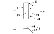
第一金具6は、図1に例示するとおり、金属板を折曲して形成したもので、固定板部61と継手板部62とを備えてなる。固定板部61は、屋根束木5の断面寸法における幅の1/2以下の幅とし、適宜箇所に釘孔63を適宜数穿設してなる。
【0014】
また継手板部62は、前記固定板部61から135度の角度で折曲されているもので、適宜数カ所にピン孔64を穿設すると共に、上縁(使用形態によっては下縁となる)を適宜な角度(好ましくは屋根勾配規格に対応させる)で下方へ傾斜させて傾斜辺65としてなる。
【0015】
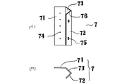
第二金具(本発明金具)7は、図2に例示するとおり、金属板を折曲して形成したもので、固定板部71と継手板部72と連結板部73とを備えてなるもので、固定板部71と継手板部72とは、互いに対面すると共に延長面が45度の角度をなし、前記固定板部71と継手板部72との頂角側を連結板部73で連結したものである。更に固定板部71の適宜数カ所に釘孔74を穿設し、継手板部72の適宜数カ所にピン孔75を穿設すると共に、連結板部73と継手板部72の上縁(使用形態によっては下縁となる)を、固定板部71と連結板部73の折曲箇所を起点として、適宜な角度(好ましくは屋根勾配規格に対応させる)で下方へ傾斜させて傾斜辺76を形成してなる。
【0016】
尚第一金具6と第二金具7は、同一種類又は異種類の金具を組み合わせて使用するものであるから、各金具6,7は、各々左右対称形状である金具であり、また両金具6,7は固定板部61,71の上辺高さを同一にした際に継手板部62,72のピン孔64,75の位置が一致するようにしておく。
【0017】
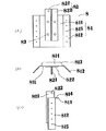
第三金具8は、図3に例示するとおり、基板81と継手板82とをビス83で連結して組み立て形成したもので、基板81は、金属板を折曲して形成したもので、基板部811の両側を前方に折曲して背後方向延長面が90度の角度をなす固定板部812を形成すると共に、基板部811の上縁を背後に折曲し、前記固定部背面と同一面となる端縁813を備えた支持板部814を形成してなる。また固定板部812の適宜数カ所に釘孔815を穿設してなる。
【0018】
継手板82は、金属板をL状に折曲したもので、折曲面の一方を継手板部821とし、他方を連結板部822としたもので、継手板部821が、基板部811の前面中央に基板部811に対して縦直交に突設するようにし、適宜数カ所にピン孔823を穿設し、且つ基板部811より上方に突出させた位置で、連結板部822を基板部811にビス83で止着してなるものである。
【0019】
次に前記金具を使用した本発明方法の実施形態について説明する。本発明金具(第二金具)と組み合わされて使用する第一金具を使用する第一の組立工法(参考工法)は、図4に例示するとおり、隅木1の上部側(屋根束木5の上部側面や、柱の出隅部分)の接合である。
【0020】
隅木1の接合は、左右対称の一対の第一金具6を、継手板部62同士を対面当接状態とし、傾斜辺65を上方に位置させて、固定板部61の上縁を屋根束木5の上端と一致させ、束木5の上端角部に固定板部61を釘着する。
【0021】
一方隅木1は、連結端面に前記継手板部62に嵌合する縦溝を予め穿設形成しておき、前記縦溝内に継手板部62を嵌合し、適宜なピンやボルトで連結してなる。
【0022】
第二の組立工法(参考工法)は、図5に例示するとおり、前記第一工法と同様に対称形状の一対の第一金具6を使用するものであるが、使用箇所が軒桁(桁材)3の出隅部分に谷木2を組み込むために、第一工法とは、上下逆にして傾斜辺65を下方に位置させて、固定板部61の上縁を桁材3の上面と一致させて、出隅形状となる桁材3の角部に固定板部61を釘着し、継手板部62を谷木の縦溝(予め縦溝を形成しておく)に差し入れて、両者を連結してなる。
【0023】
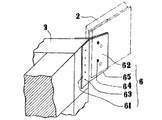
第三の組立工法(本発明工法)は、図6に例示するとおり、建築物に高さが異なる2箇所の棟が形成され、低い側の棟端において昇り勾配の隅木1と下り勾配の谷木2が同一箇所に取付き、当該位置において上端高さが等しい棟木4と束木5が接合されている場合等、特に母屋桁材や、棟木等の側面部分に棟木や谷木を連結する場合の工法である。
【0024】
即ち第一金具6と第二金具7を、継手板部62,72を対面当接させて組み合わせ、各金具6,7の固定板部61,71を棟木4の側面等に釘着し、対面当接した継手板部62,72に谷木2を連結してなるものである。この場合に、傾斜辺65,76は上方に位置するように組み合わせてなる。
【0025】
尚第三組立工法は、隅木1や谷木2の桁材3から連結方向並びに、隅木1や谷木2の選択によって左右対称の二種類の金具の組み合わせと、金具上下の使い分けによって全てに対応する。勿論図6に例示するように、隣接する隅木1や谷木2に対しては、前記の第一工法又は第二工法が適用されるものである。
【0026】
本発明の第四の組立工法(参考工法)は、図7に例示するとおり軒桁(桁材)3の直交入隅部に隅木1を取付ける為のもので、第三金具8を入隅部分に使用するものである。
【0027】
即ち第三金具8の両固定板部812を、桁材3の直交入隅形状の内側面箇所に、その上縁を桁材3の上面と一致させて釘着し、継手板部821に隅木1をその縦溝を使用してボルトやピン体で連結してなるものである。
【0028】
特に図示した例は、隅木1の場合を示したもので、金具8における基板81より継手板82が上方に突出した状態で使用しているが、谷木に対して使用する場合には、金具を上下逆転して使用する。
【0029】
【発明の効果】
以上のように本発明は、固定板部と継手板部と連結板部とを備え、固定板部と継手板部とは、互いに対面すると共に延長面が45度の角度をなし、前記固定板部と継手板部との頂角側を連結板部で連結した金具(第二金具)と、釘孔を設けた固定板部とピン孔を設けた継手板部とを備え、継手板部を前記固定板部から135度の角度で折曲してなる汎用性を有する第一金具とを組み合わせ、隅木や谷木を束木や桁材の側面に連結する組立工法で、製造容易な金具を採用して、隅木や谷木ならびに桁材等の切欠き加工を無くし、且つ隅木や谷木が載る屋根面材と軒桁との隙間をなくしての接合を可能としたものである。
【図面の簡単な説明】
【図1】本発明金具と組み合わせ使用される第一金具の説明図で、(イ)は正面図(ロ)は平面図。
【図2】本発明金具(第二金具)の説明図で、(イ)は正面図(ロ)は平面図。
【図3】参考第三金具の説明図で、(イ)は正面図(ロ)は平面図(ハ)は側面図。
【図4】参考第一工法の実施形態説明図。
【図5】同第二工法の実施形態説明図。
【図6】本発明工法(第三工法)の実施形態説明図で、(イ)は斜視図(ロ)は平面図。
【図7】参考第四工法の実施形態説明図。
【図8】従来例の説明図。
【符号の説明】
1 隅木
2 谷木
3 桁材(横架材)
4 棟木(横架材)
5 束木
6 第一金具
61 固定板部
62 継手板部
63 釘孔
64 ピン孔
65 傾斜辺
7 第二金具
71 固定板部
72 継手板部
73 連結板部
74 釘孔
75 ピン孔
76 傾斜辺
8 第三金具
81 基板
811 基板部
812 固定板部
813 端縁
814 支持板部
815 釘孔
82 継手板
821 継手板部
822 連結板部
823 ピン孔
83 ビス[0001]
[Industrial applications]
TECHNICAL FIELD The present invention relates to a joint fitting used for assembling corners and valleys of a roof of a building having a corner building, and an assembling method using the fitting.
[0002]
Problems to be solved by the prior art and the invention
As shown in FIG. 8, corners and valleys serving as framing of corner roofs in the conventional wooden frame construction method include corners 01 and valleys 02, and eaves girders, purlins or purlins serving as supporting members thereof. At the joint with the girder member (horizontal member) 03, both members were cut out and combined. However, the dimensional determination and implementation work of the notch processing requires skill and a great deal of labor, and there is a problem that a cross-sectional defect occurs in both members. A structure in which a gap is formed between the roof surface material supported by the corners 01 and the valleys 02 and the girder member 03 is disadvantageous for imparting a heat insulating function to the building.
[0003]
Therefore, a construction method has been proposed in which no gap is formed between the roof surface material supported by the corner trees 01 and the valleys 02 and the eaves girder (girder material) 03, and the notch processing of the members can be omitted.
[0004]
For example, Japanese Unexamined Patent Publications Nos. 09-302832 and 09-302833 disclose metal fittings provided with joint plates of right and left corners fixed to the side of a bundle, but the metal fittings are fixed on one side. There is an uneasiness in strength because it connects two or more corner trees in the part, and in order to increase the reliability of strength, fixing the bracket to the stake is a bolt, complicating the connection structure between the sash and the purlin I have.
[0005]
The above-mentioned publication also discloses a metal fitting for connecting a corner block to an eaves girder. This metal fitting has a vertical plate-like joint plate that connects the corners to a fixing plate that is fixed on the upper surface of the eaves girder and on the fire beam on the corner side. There is a problem that it can be used only in a part and a place where a fired beam is adopted, and lacks versatility. Further, each of the above-mentioned metal fittings requires a welded portion, and it is naturally necessary to perform a rust prevention treatment on the welded portion, which also increases the cost.
[0006]
Japanese Unexamined Patent Publication No. 10-96290 also discloses a metal fitting for connecting a corner block to the entry corner of an eaves girder. This metal fitting adopts a complicated structure of connecting the butterfly plate between the fixed part to the eaves girder and the joint plate part connected to the corner block, and as a result of the adoption of the butterfly plate connecting structure, the joint plate part side further It is necessary to provide a triangular cylindrical receiving plate, and the whole fitting is complicated, and its manufacture is complicated.
[0007]
In view of the above, the present invention proposes a metal fitting for connecting a corner wood or a valley to the side surface of a girder by using a metal fitting with versatility used for incorporating a corner wood or a valley, and a method of using the metal fitting.
[0008]
[Means for Solving the Problems]
The first metal fitting combined with the metal fitting according to the present invention includes a fixed plate part and a joint plate part, the fixed plate part has a width of 1/2 or less of the roof bunch, and the joint plate part is separated from the fixed plate part. It is bent at an angle of 135 degrees, and a nail hole is formed in the fixed plate portion, a pin hole is formed in the joint plate portion, and an upper edge of the joint plate portion is formed on a downward inclined side at an appropriate angle. It is characterized by becoming.
[0009]
Further, the metal fitting (second metal fitting) according to the present invention includes a fixed plate part, a joint plate part, and a connecting plate part. The fixed plate part and the joint plate part face each other and have an extended surface having an angle of 45 degrees. None, the apex side of the fixed plate portion and the joint plate portion are connected by a connecting plate portion, and a nail hole and a pin hole are formed in the fixed plate portion and the joint plate portion. The edge is formed on the lower inclined side at an appropriate angle.
[0010]
In the assembling method according to the present invention, the first metal fitting and the second metal fitting are combined by bringing the joint plate portions thereof into contact with each other, the fixing plate part is nailed to a side surface of the girder material or the like, and the corner plate is attached to the joint plate part. Or, it is characterized by connecting valleys.
[0011]
Therefore, it is possible to connect and integrate corners and valleys at various locations by combining metal fittings having a simple shape without requiring a welding structure.
[0012]
Embodiment
Next, an embodiment of the present invention will be described. According to the present invention method and other reference methods, in a building employing a wooden frame construction method having a corner ridge, a corner sill 1 to be passed from a ridge part (a ridge 4 and a shackle 5) of a roof or a purlin part to a girder 3 is used. The present invention relates to the joining of the valley and the valley 2 with the ridge 4 and the sash 5 and the girder material (horizontal member) 3 such as the purlin or ridge, which are the above-mentioned supporting members. And three types of joining fittings including the joining fitting according to the above.
[0013]
As illustrated in FIG. 1, the first metal fitting 6 is formed by bending a metal plate, and includes a fixed plate portion 61 and a joint plate portion 62. The fixed plate portion 61 has a width equal to or less than の of the width in the cross-sectional dimension of the roof bunch 5, and is provided with an appropriate number of nail holes 63 at appropriate locations.
[0014]
The joint plate portion 62 is bent at an angle of 135 degrees from the fixed plate portion 61. The joint plate portion 62 is provided with pin holes 64 at several places as appropriate, and has an upper edge (or a lower edge depending on a use form). Is inclined downward at an appropriate angle (preferably corresponding to the roof gradient standard) to form an inclined side 65.
[0015]
As illustrated in FIG. 2, the second metal fitting (the metal fitting of the present invention) 7 is formed by bending a metal plate, and includes a fixed plate 71, a joint plate 72, and a connecting plate 73. The fixed plate portion 71 and the joint plate portion 72 face each other and the extension surface forms an angle of 45 degrees, and the vertex angle side of the fixed plate portion 71 and the joint plate portion 72 is connected by the connecting plate portion 73. It was done. Further, nail holes 74 are drilled at appropriate places of the fixing plate 71, pin holes 75 are drilled at appropriate places of the joint plate 72, and the upper edges of the connecting plate 73 and the joint plate 72 (depending on usage). Is a lower edge) of the fixed plate portion 71 and the connecting plate portion 73 as a starting point, and is inclined downward at an appropriate angle (preferably corresponding to a roof slope standard) to form an inclined side 76. It becomes.
[0016]
Since the first metal fitting 6 and the second metal fitting 7 are used in combination of the same kind or different kinds of metal fittings, each of the metal fittings 6 and 7 is a metal fitting which is symmetrical to the left and right. , 7 are arranged such that the pin holes 64, 75 of the joint plate portions 62, 72 coincide with each other when the upper sides of the fixed plate portions 61, 71 have the same height.
[0017]
As illustrated in FIG. 3, the third metal fitting 8 is formed by connecting a substrate 81 and a joint plate 82 with screws 83, and the substrate 81 is formed by bending a metal plate. Both sides of the portion 811 are bent forward to form a fixed plate portion 812 having a rearward extending surface forming an angle of 90 degrees, and the upper edge of the substrate portion 811 is bent behind to be the same as the back surface of the fixed portion. A support plate portion 814 having an edge 813 serving as a surface is formed. Also, nail holes 815 are formed at appropriate places on the fixing plate 812.
[0018]
The joint plate 82 is formed by bending a metal plate into an L shape. One of the bent surfaces is a joint plate portion 821 and the other is a connection plate portion 822. The joint plate portion 821 is a front surface of the substrate portion 811. The connecting plate 822 is attached to the substrate 811 at a position where it is projected vertically and perpendicularly to the substrate 811 at the center, and pin holes 823 are drilled at appropriate places, and protrudes above the substrate 811. It is fixed with screws 83.
[0019]
Next, an embodiment of the method of the present invention using the metal fitting will be described. As illustrated in FIG. 4, a first assembling method (reference method) using the first metal fitting used in combination with the metal fitting of the present invention (second metal fitting) is an upper side of the corner block 1 (an upper part of the roof bundle 5). Side and the corners of pillars).
[0020]
The joining of the corner block 1 is performed by placing the pair of symmetrical first metal fittings 6 such that the joint plate portions 62 are in a face-to-face contact state, the inclined side 65 is positioned upward, and the upper edge of the fixed plate portion 61 is attached to the roof bundle. The fixing plate 61 is nailed to the upper end corner of the bundle 5 so as to match the upper end of the bundle 5.
[0021]
On the other hand, in the corner block 1, a vertical groove for fitting to the joint plate portion 62 is formed in advance on the connection end face, and the joint plate portion 62 is fitted in the vertical groove and connected with an appropriate pin or bolt. It becomes.
[0022]
As shown in FIG. 5, the second assembling method (reference method) uses a pair of symmetrically shaped first metal fittings 6 as in the first method. 3) In order to incorporate the valley 2 into the protruding corner portion of 3, the first construction method is turned upside down so that the inclined side 65 is located below and the upper edge of the fixing plate portion 61 coincides with the upper surface of the girder member 3. Then, the fixing plate portion 61 is nailed to the corner portion of the girder member 3 having a protruding corner shape, and the joint plate portion 62 is inserted into a vertical groove of the valley (a vertical groove is formed in advance), and both are inserted. Be connected.
[0023]
In the third assembling method (method of the present invention), as illustrated in FIG. 6, two buildings having different heights are formed in a building, and a corner block 1 having a rising slope and a valley having a down slope are formed at a lower side of the building. In the case where the trees 2 are attached to the same place and the purlins 4 and the bundles 5 having the same upper end height are joined at this position, the purlins and valleys are particularly connected to the side members of the purlin girder material and the purlins. It is a construction method in the case.
[0024]
That is, the first metal fitting 6 and the second metal fitting 7 are combined by bringing the joint plate parts 62 and 72 into face-to-face contact, and the fixing plate parts 61 and 71 of the metal fittings 6 and 7 are nailed to the side face of the purlin 4 and the like. The valley 2 is connected to the joint plate portions 62 and 72 that are in contact with each other. In this case, the inclined sides 65 and 76 are combined so as to be located above.
[0025]
In addition, the third assembling method corresponds to the combination of the two types of symmetrical metal fittings by selecting the connecting direction from the girder 3 of the corner block 1 and the valley 2 and the selection of the corner block 1 and the valley 2, and using the upper and lower brackets to handle all. I do. Of course, as illustrated in FIG. 6, the above-described first method or second method is applied to the adjacent corners 1 and valleys 2.
[0026]
The fourth assembling method (reference method) of the present invention is for attaching a corner block 1 to an orthogonal corner of an eave girder (girder material) 3 as illustrated in FIG. It is used for
[0027]
That is, the two fixing plate portions 812 of the third metal fitting 8 are nailed to the inside surface of the orthogonally-inserted corner shape of the girder member 3 with its upper edge coincident with the upper surface of the girder member 3. 1 are connected by bolts or pins using the vertical grooves.
[0028]
In particular, the illustrated example shows the case of the corner block 1, which is used with the joint plate 82 projecting upward from the substrate 81 of the bracket 8. Is used upside down.
[0029]
【The invention's effect】
As described above, the present invention includes the fixed plate portion, the joint plate portion, and the connecting plate portion, wherein the fixed plate portion and the joint plate portion face each other and the extended surface forms an angle of 45 degrees, (A second metal fitting) in which the apex side of the portion and the joint plate are connected by a connecting plate, a fixing plate having a nail hole, and a joint plate having a pin hole. Combination with a versatile first metal fitting that is bent at an angle of 135 degrees from the fixing plate portion, and an assembly method that connects corners and valleys to the side surfaces of bundles and girder materials, to produce a metal fitting that is easy to manufacture. By adopting this method, it is possible to eliminate notches in corners, valleys, and girder members, and to perform joining without a gap between the roof surface material on which the corners and valleys are mounted and the eaves girder.
[Brief description of the drawings]
FIG. 1 is an explanatory view of a first metal fitting used in combination with the metal fitting of the present invention, wherein (a) is a front view and (b) is a plan view.
FIGS. 2A and 2B are explanatory views of the metal fitting of the present invention (second metal fitting), wherein FIG. 2A is a front view and FIG.
FIG. 3 is an explanatory view of a reference third metal fitting, wherein (a) is a front view, (b) is a plan view, and (c) is a side view.
FIG. 4 is an explanatory view of an embodiment of the first reference method.
FIG. 5 is an explanatory view of an embodiment of the second method.
FIG. 6 is an explanatory view of the embodiment of the present invention method (third method), wherein (a) is a perspective view and (b) is a plan view.
FIG. 7 is an explanatory view of an embodiment of a fourth reference method.
FIG. 8 is an explanatory view of a conventional example.
[Explanation of symbols]
1 corner wood 2 valley 3 girder material (horizontal material)
4 purlin (horizontal material)
5 Bundling 6 First metal fitting 61 Fixed plate 62 Joint plate 63 Nail hole 64 Pin hole 65 Inclined side 7 Second metal fitting 71 Fixed plate 72 Joint plate 73 Connection plate 74 Nail hole 75 Pin hole 76 Inclined side 8 Third metal fitting 81 Board 811 Board portion 812 Fixed plate portion 813 Edge 814 Support plate portion 815 Nail hole 82 Joint plate 821 Joint plate portion 822 Connecting plate portion 823 Pin hole 83 Screw