JP3553044B2 - Arc tube manufacturing method - Google Patents
Arc tube manufacturing method Download PDFInfo
- Publication number
- JP3553044B2 JP3553044B2 JP2001400857A JP2001400857A JP3553044B2 JP 3553044 B2 JP3553044 B2 JP 3553044B2 JP 2001400857 A JP2001400857 A JP 2001400857A JP 2001400857 A JP2001400857 A JP 2001400857A JP 3553044 B2 JP3553044 B2 JP 3553044B2
- Authority
- JP
- Japan
- Prior art keywords
- sealing
- light emitting
- light
- arc tube
- laser beam
- Prior art date
- Legal status (The legal status is an assumption and is not a legal conclusion. Google has not performed a legal analysis and makes no representation as to the accuracy of the status listed.)
- Expired - Fee Related
Links
Images



Landscapes
- Non-Portable Lighting Devices Or Systems Thereof (AREA)
- Manufacture Of Electron Tubes, Discharge Lamp Vessels, Lead-In Wires, And The Like (AREA)
- Vessels And Coating Films For Discharge Lamps (AREA)
Description
【0001】
【発明の属する技術分野】
本発明は、発光管の製造方法に関するものである。
【0002】
【従来の技術】
従来の放電ランプ、例えば高圧水銀ランプには、内部に電極が設けられ、かつ水銀や希ガス等が封入された発光部と、この発光部の両端部に形成された封止部とを有する石英ガラス製の発光管を備えたものが知られている。
【0003】
このような従来の高圧水銀ランプの製造方法、特にそれに用いられている発光管の封止部形成方法としては、発光管の材料である直管状の石英ガラス管の封止部形成予定部を加熱軟化させてピンチ封止またはシュリンク封止する方法がある。
【0004】
石英ガラス管を加熱軟化させる熱源には、一般的に使用されているガスバーナーに比して加工精度が高く、封止耐圧の高い高品質な発光管を得ることができるレーザービームを用いることが提案されている(特開昭57−109234号公報や特許第2997464号公報等)。
【0005】
【発明が解決しようとする課題】
しかしながら、このようなレーザービームを用いた従来の高圧水銀ランプの製造方法では、レーザービームが被加工物である石英ガラス管に対して局部的にしか加熱できないため、特に封止部の長さが長い発光管を製造する場合、石英ガラス管の長尺な封止部形成予定部全体を加熱軟化させるのに要する時間が長くなり、生産効率が低くなるという問題とともに、封止部形成予定部全体を十分に加熱軟化させるのに大出力のレーザービームが必要となるため、装置が大型化してコストが高くなるという問題があった。
【0006】
本発明は、このような問題を解決するためになされたもので、耐圧性の高い高品質な発光管を得ることができ、かつ生産効率を向上させることができる低コストな発光管の製造方法を提供することを目的とする。
【0007】
【課題を解決するための手段】
本発明の発光管の製造方法は、内部に電極が設けられた発光部と、この発光部の端部に形成された封止部とを有する発光管の製造方法であって、前記発光管の材料である透光性絶縁管の発光部形成予定部に隣接した封止部形成予定部に前記電極を有する電極体を挿入し、その後、前記封止部形成予定部のうち前記発光部形成予定部側の端部を前記レーザービームによって加熱軟化させて封止し、前記封止部形成予定部の前記発光部形成予定部側の端部以外の部分を前記ガスバーナーによって加熱軟化させて封止し、前記封止部を形成する。
【0008】
これにより、封止部形成予定部を加熱軟化させる熱源であるレーザービームとガスバーナーとを封止部形成予定部の各領域ごとに適宜使い分けることができる。特に封止部形成予定部のうち高い加工精度が求められる部分、例えば封止部形成予定部の発光部形成予定部側の端部においてレーザービームを用いることで、歪みがなく、かつより気密な封止を行うことができ、耐圧性の高い高品質な発光管を得ることができる。また封止部形成予定部の高い加工精度が求められる部分以外の部分においてはレーザービームに比して熱容量が大きくかつ加熱範囲が広いガスバーナーを用いることで、広範囲な領域を短時間で封止することができるので、生産効率を向上させることができる。また、レーザービームによって加熱軟化させる領域を特に高い加工精度が求められる部分に限定することで、出力の小さいレーザービームを使用することが可能となり、それにともない装置を小型化することができ、低コスト化を図ることができる。
【0010】
【発明の実施の形態】
以下、本発明の実施の形態について、図面を用いて説明する。
【0011】
(実施の形態1)
本発明の実施の形態である発光管の製造方法を用いて製造された高圧水銀ランプの発光管1は、石英ガラス製であり、図5に示すように、長さ10mm、最大外径10mmの回転楕円体状の発光部2と、この発光部2の両端部に形成された長さ25mm、外径6mmの円柱状の封止部3とを備えている。
【0012】
発光部2内の両端部には、先端部に電極コイル4が取り付けられた電極リード棒5を有するタングステン製の電極6が設けられている。この電極6は、封止部3に封止されたモリブデン等の金属箔7を介してリード線8に接続されている。
【0013】
また、発光部2内には、水銀、金属ハロゲン化物、および希ガス等がそれぞれ所定量封入されている。
【0014】
次に、このような高圧水銀ランプの発光管1の製造方法について説明する。
【0015】
発光管1の材料としては、図1に示すような石英ガラス製の直管状の透光性絶縁管9を用いる。
【0016】
まず、この透光性絶縁管9に後述の発光部形成予定部15を形成する。以下、その手順について説明する。
【0017】
図示はしていないが、この透光性絶縁管9の中央部を酸素と水素とを燃料とするガスバーナによって加熱軟化させる。その後、透光性絶縁管9の一方の開口部12を一時的に閉じ、不活性ガスを透光性絶縁管9の他方の開口部12から透光性絶縁管9内へ吹き込むことにより、透光性絶縁管9の軟化した部分をその不活性ガスの圧力によって膨らませる。さらに、透光性絶縁管9の膨らんだ部分に金型を押し当てることにより、その部分を回転楕円体状に成型する。このようにして発光部形成予定部15を形成する。
【0018】
次に、透光性絶縁管9の発光部形成予定部15に隣接し、かつ内部が連通した部分、すなわち後述の封止部形成予定部13a,13bを封止し、封止部3を形成する。以下、その手順について説明する。
【0019】
図1に示すように、透光性絶縁管9を垂直に立てた状態でその両端部をチャック10によって挟み込み、透光性絶縁管9を保持する。次に、後述の電極体11を透光性絶縁管9の封止を行う側の開口部12から透光性絶縁管9の封止部形成予定部13a内へ挿入する。
【0020】
電極体11とは、電極6、金属箔7およびリード線8をそれぞれ組み立て一体化した組立部品である。また、電極体11のリード線8の端部には一部が封止部形成予定部13aの内面に圧接した菱形状のばね14が取り付けられており、電極体11はこのばね14の弾性応力によって封止部形成予定部13a内の所定位置に保持されている。
【0021】
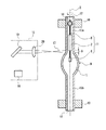
電極体11の挿入後、透光性絶縁管9の長手方向の軸X(図1参照)を中心として、透光性絶縁管9を一定速度で回転させながら、封止部形成予定部13aの発光部形成予定部15側の端部、すなわち領域A(図1参照)にレーザービーム発振装置16から発振されたレーザービーム17を照射して、領域Aを加熱軟化させて収縮によって密閉する。すなわちシュリンク封止する。封止の際、透光性絶縁管9内はアルゴンガス等の不活性ガスで満たされている。
【0022】
なお、図1中、18はレーザービーム17を発振する光源部を、19はレーザービーム17を反射させる反射鏡を、20はレーザービーム17を集光する集光レンズをそれぞれ示す。
【0023】
レーザービーム17には、例えば炭酸ガスレーザー、エキシマレーザー、YAG(イットリウムアルミニウムガーネット)レーザー、半導体レーザー等を用いることができる。
【0024】
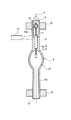
次に、図1に示す状態から図2に示すように、レーザービーム発振装置16を上方へ移動させ、透光性絶縁管9の領域Aに隣接した領域B(図2参照)にレーザービーム17を照射して、領域Bを加熱軟化させる。領域Bにレーザービーム17を照射するのと同時に、または領域Bがレーザービーム17によってシュリンク封止されてしまう前にガスバーナー21を点火し、ガスバーナー21の炎を領域Bの一部と、透光性絶縁管9の領域Bに隣接した領域C(図2参照)の一部に当てる。これによって領域Bをレーザービーム17とガスバーナー21との両方によって加熱軟化し、シュリンク封止する。
【0025】
なお、完成した発光管1を点灯させた際、電極リード棒5の根元部分には発光部2内に封入された高圧の封入ガスが侵入してクラックが発生しやすい。したがって、電極リード棒5の根元部分を含む領域Aは、特に気密性が高くかつ歪みのない加工が必要となる。
【0026】
領域Bを封止した後、レーザービーム17の照射を停止し、図3に示すようにガスバーナー21を上方へ連続的に移動させて、つまり領域Cにおいて発光部形成予定部15側から発光部形成予定部15とは反対側へ向かって順次加熱軟化してシュリンク封止する。このようにして封止部形成予定部13a全体を封止し、一方の封止部3を形成する。
【0027】
次に、図3に示す状態から図4に示すように、透光性絶縁管9の上下を反転させて、封止部3が下側に位置するように透光性絶縁管9を垂直に立てた状態でその両端部をチャック10によって保持する。
【0028】
そして、他方の封止部形成予定部13bの開口部12から水銀等の封入物を投入した後、同じく封止部形成予定部13bの開口部12から電極体11を挿入して封止部形成予定部13b内の所定位置に保持する。
【0029】
その後、上記した一方の封止部3の形成手順と同じ手順で他方の封止部形成予定部13bを封止し、他方の封止部3を形成する。封止部形成予定部13bを加熱軟化させる際、図示はしていないが、発光部形成予定部15内の封入物、例えば水銀が蒸気化しないように、発光部形成予定部15を液体窒素等によって冷却しながら行うことが好ましい。
【0030】
発光部2は、各々の封止部3が形成されると同時に形成されることになる。
【0031】
発光部2および封止部3が形成された後、透光性絶縁管9の両端部の領域D(図4参照。ただし、図4中、一方のみ図示)を切り落とし、図5に示すような発光管1が製造される。
【0032】
この後、発光管1に口金(図示せず)等が取り付けられ高圧水銀ランプが製造される。
【0033】
このような発光管の製造方法を用いて定格電力150Wの高圧水銀ランプの発光管1(以下、「本発明品」という)を製造したところ、一箇所の封止部形成予定部13a(長さ25mm、外径6mm、厚さ2mm)を封止するのに要した時間は、領域Aと領域Bとの合計長さが2.2mmとして、82秒であった。
【0034】
また、比較のために、封止部形成予定部13a全体をレーザービーム17のみによって封止する点を除いて本発明の上記の実施の形態と同じ製造方法を用いて、同じく定格電力150Wの高圧水銀ランプの発光管1(以下、「比較品」という)を製造したところ、一箇所の封止部形成予定部13aを封止するのに要した時間は400秒であった。
【0035】
なお、レーザービーム17には、出力80Wの炭酸ガスレーザーをそれぞれ用いた。
【0036】
また、本発明品および比較品を定格電力でそれぞれ点灯させたところ、両者とも定格寿命(2000時間)中、発光管1にクラックが発生したものはなかった。よって、両者とも耐圧性が高いことが確認された。
【0037】
以上のように本発明の発光管の製造方法においては、発光管1の材料である透光性絶縁管9の発光部形成予定部15に隣接した封止部形成予定部13a,13bに電極6を有する電極体11を挿入し、その後、封止部形成予定部13a,13bをレーザービーム17とガスバーナー21との併用によって加熱軟化させて封止し、封止部3を形成する。このとき、封止部形成予定部13a,13bを加熱軟化させる熱源であるレーザービーム17とガスバーナー21とを封止部形成予定部13a,13bの各領域ごとに適宜使い分けることが好ましい。特に封止部形成予定部13a,13bのうち高い加工精度が求められる部分、例えば封止部形成予定部13a,13bの発光部形成予定部15側の端部においてレーザービーム17を用いることで、歪みがなく、かつより気密な封止を行うことができ、耐圧性の高い高品質な発光管1を得ることができる。また、封止部形成予定部13a,13bの高い加工精度が求められる部分以外の部分においてはレーザービーム17に比して熱容量が大きくかつ加熱範囲が広いガスバーナー21を用いることで、広範囲な領域を短時間で封止することができるので、生産効率を向上させることができる。また、レーザービーム17によって加熱軟化させる領域を限定することで、出力の小さいレーザービーム17を使用することが可能となり、それにともない装置を小型化することができ、低コスト化を図ることができる。
【0038】
特に、上述したように封止部形成予定部13a,13bのうち発光部形成予定部15側の端部をレーザービーム17によって加熱軟化して封止することが好ましい。これにより、発光部2の電極リード棒5の根元部分の発光部2の内面が図5に示すような滑らかな平面または曲面にすることができるので、その部分の耐圧性を向上させることができる。
【0039】
また、封止部形成予定部13a,13bのうち発光部形成予定部15側の端部(例えば領域A)をレーザービーム17によって加熱軟化させて封止し終える直前または封止し終えた後、封止部形成予定部13a,13bのうちレーザービーム17によって加熱軟化させた領域(以下、単に「領域Y」という)に隣接する領域(以下、単に「領域Z」という)をガスバーナー21によって加熱軟化し始めることが好ましい。これにより、領域Zをガスバーナー21によって加熱軟化させる際、領域Zはこの領域Zに隣接した領域Yが加熱されたときの熱によって予熱されているので、領域Zを短時間で封止することができ、その結果、発光部形成予定部15が広がりをもつガスバーナー21の炎にさらされる時間が短くなり、よって、発光部形成予定部15内に封入ガスが封入されている場合において、封入ガスの熱膨張による発光部形成予定部15の破損を防止することができる。
【0040】
また、封止部形成予定部13a,13bにおいて、例えば領域Bのようにレーザービーム17によって加熱軟化させる領域の少なくとも一部と、ガスバーナー21によって加熱軟化させる領域の一部とが重なっていることが好ましい。これにより、レーザービーム17によって加熱軟化させる領域とガスバーナー21によって加熱軟化させる領域との境界部分の温度がその境界部分の周辺部分の温度より低くなって封止が十分に行えず、それによって気密性が低下してその部分に気泡が混入するのを防止することができる。また形成後の封止部3に歪みが生じて、耐圧性が低下するのを防止することができる。
【0041】
さらに、封止部形成予定部13a,13bを、発光部形成予定部15側の端部から発光部形成予定部15とは反対側の端部へ向かって順次封止していくことが好ましい。これにより、封止する際に、封止部形成予定部13a,13b内の封入ガスが全て透光性絶縁管9の外部に排出することができる。よって封止部形成予定部13a,13b内の封入ガスが発光部形成予定部15内に圧縮され、発光部形成予定部15内のガス圧力が過剰に高くなって、発光部形成予定部15が破損するのを防止することができる。
【0042】
しかし、例えば発光部形成予定部15内のガス圧がもともと低かったり、発光部形成予定部15の肉厚が十分に厚かったりした場合は、封止部形成予定部13a,13bを、発光部形成予定部15とは反対側の端部から発光部形成予定部15側の端部へ向かって順次封止していくことが好ましい。これにより、封止部形成予定部13a,13b内の封入ガスを発光部形成予定部15内に圧縮し、封止部形成予定部13a,13b内の封入ガスを無駄なく有効に利用することができる。この場合、最初に、封止部形成予定部13a,13bを、発光部形成予定部15とは反対側の端部から発光部形成予定部15側の端部へ向かってガスバーナーにより封止し、最後に、封止部形成予定部13a,13bのうち発光部形成予定部15側の端部をレーザービームにより封止し終えることが好ましい。
【0043】
なお、上記実施の形態では、石英ガラス製の透光性絶縁管9を用いた場合について説明したが、石英ガラス以外に例えば硼珪酸塩ガラスや透光性アルミナ等の透光性絶縁管を用いた場合でも上記と同様の効果を得ることができる。
【0044】
また、上記実施の形態では、軟化した封止部形成予定部13a,13bを封止する方法として、シュリンク封止を用いた場合について説明したが、これ以外に軟化した封止部形成予定部13a,13bを挟み込んで押しつぶす、すなわちピンチ封止を用いた場合でも上記と同様の効果を得ることができる。
【0045】
また、上記実施の形態では、封止部形成予定部13a,13bにおいて、レーザービーム17によって加熱軟化させる領域を領域A、領域B、またガスバーナー21によって加熱軟化させる領域を領域Cとしたが、レーザービーム17によって加熱軟化させる領域、またガスバーナー21によって加熱軟化させる領域は適宜選択することができる。例えば領域Bをガスバーナー21によって、また領域Cの一部をレーザービーム17によってそれぞれ加熱軟化させてもよい。
【0046】
さらに、上記実施の形態では、高圧水銀ランプの発光管の製造方法を例示して説明したが、本発明は例えばメタルハライドランプや片封止形の放電ランプ等における発光管の製造方法にも適用することができる。
【0047】
(実施の形態2)
図6は、実施の形態1で説明した本発明の製造方法によって得た発光管を用いた反射鏡(リフレクタ)付き放電ランプの一例を示した一部切り欠き斜視図である。
【0048】
図示したように、本実施の形態の反射鏡付き放電ランプ30は、反射鏡31と、実施の形態1の製造方法に従い製造された発光管1とからなる。発光管1は、電極コイル4(図5参照)間に形成されるアーク軸が反射鏡31の光軸上に位置するように、反射鏡31内側に反射鏡31と一体化されている。反射鏡31は、セラミック製で、漏斗形状を有し、その内面に酸化チタン−酸化シリコンの蒸着膜からなる反射面を有している。反射鏡31の開口とは反対側の端部に筒部31aを有する。
【0049】
発光管1の一方の封止部3(図5参照)には口金35が取り付けられている。この口金35が反射鏡31の筒部31a内に挿入され、絶縁セメント37により両者が固着されることによって、反射鏡31と発光管1とが一体化されている。
【0050】
発光管1の一方のリード線8(図5参照)は口金35に電気的に接続される。また、他方のリード線8は、電力供給線39の一端に接続される。電力供給線39の他端は反射鏡31を貫通し、反射鏡31の反射面とは反対側に導出されている。
【0051】
以上の反射鏡付き放電ランプ30は、例えば、液晶プロジェクタの光源として使用される。
【0052】
(実施の形態3)
図7は、実施の形態1で説明した本発明の製造方法によって得た発光管を用いた自動車前照灯用放電ランプの一例を示した断面図である。
【0053】
図示したように、本実施の形態の35W自動車前照灯用放電ランプ40は、実施の形態1の製造方法に従い製造された発光管1と、外管42と、口金43とからなる。
【0054】
発光管1は、発光部2と、その両端の封止部3a,3bと、一方の封止部3bの端部に連設した筒状の円筒部(未封止部分)1aとを有する。
【0055】
外管42は発光管1を包囲し、外管42の両端は発光管1の両端の外周面に融着されている。
【0056】
口金43はポリエーテルイミド等の樹脂からなる。発光管1の円筒部1a側の端部が口金43の中央の穴に挿入されるとともに、口金43に取り付けられた保持体44が外管42の一方の端部を保持することにより、発光管1は口金43に保持されている。
【0057】
発光管1の発光部2内には、一対の電極6a,6bを有するとともに、水銀と、金属ハロゲン化物としてScI3、NaIと、始動用ガスとしてキセノンとが封入されている。一方の電極6aは、金属箔7aを介してリード線8aに接続され、リード線8aは電力供給線45の一端に接続される。電力供給線45は外管42の外側にこれと略平行に配置され、電力供給線45の他端は口金43に設けられた電力供給端子47aに接続されている。また、他方の電極6bは、金属箔7bを介してリード線8bに接続され、リード線8bは口金43に設けられた電力供給端子47bに接続されている。
【0058】
上記の実施の形態2,3の放電ランプは、上記実施の形態1に示した製造方法により得られた発光管を備えるので、発光管の耐圧性が高く、高品質で、生産性が高く、低コストである。
【0059】
なお、本発明の製造法により得られた発光管を備える放電ランプの構成は上記の実施の形態2,3に示した例に限定されない。本発明の発光管は、公知の放電ランプの発光管として広く使用することができる。
【0060】
【発明の効果】
以上説明したように、本発明は、耐圧性の高い高品質な発光管を得ることができるとともに、生産効率を向上させることができる低コストな発光管の製造方法を提供することができるものである。
【図面の簡単な説明】
【図1】本発明の発光管の製造方法の一実施形態の一工程を説明するための断面図
【図2】同じく発光管の製造方法の一実施形態の一工程を説明するための断面図
【図3】同じく発光管の製造方法の一実施形態の一工程を説明するための断面図
【図4】同じく発光管の製造方法の一実施形態の一工程を説明するための断面図
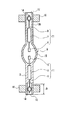
【図5】本発明の製造方法によって製造された発光管の正面断面図
【図6】本発明の製造方法によって製造された発光管を用いた反射鏡付き放電ランプの一実施形態を示した一部切り欠き斜視図
【図7】本発明の製造方法によって製造された発光管を用いた自動車前照灯用放電ランプの一実施形態を示した断面図
【符号の説明】
1 発光管
2 発光部
3 封止部
4 電極コイル
5 電極リード棒
6 電極
7 金属箔
8 リード線
9 透光性絶縁管
10 チャック
11 電極体
12 開口部
13a,13b 封止部形成予定部
14 ばね
15 発光部形成予定部
16 レーザービーム発振装置
17 レーザービーム
18 光源部
19 反射鏡
20 集光レンズ
21 ガスバーナー
30 反射鏡付き放電ランプ
31 反射鏡
31a 筒部
35 口金
37 絶縁セメント
39 電力供給線
40 自動車前照灯用放電ランプ
42 外管
43 口金
44 保持体
45 電力供給線
47a,47b 電力供給端子[0001]
TECHNICAL FIELD OF THE INVENTION
The present invention relates to the production how the arc tube.
[0002]
[Prior art]
A conventional discharge lamp, for example, a high-pressure mercury lamp has a light emitting portion in which electrodes are provided and in which mercury, a rare gas, or the like is sealed, and quartz having sealing portions formed at both ends of the light emitting portion. A device equipped with a glass arc tube is known.
[0003]
As a method of manufacturing such a conventional high-pressure mercury lamp, particularly a method of forming a sealed portion of an arc tube used therein, a portion to be formed of a straight quartz glass tube, which is a material of the arc tube, is heated. There is a method of pinching or shrink sealing by softening.
[0004]
As a heat source for heating and softening the quartz glass tube, a laser beam that can obtain a high-quality arc tube with higher processing accuracy and higher sealing pressure than the commonly used gas burner should be used. It has been proposed (Japanese Patent Laid-Open No. 57-109234, Japanese Patent No. 2999764, etc.).
[0005]
[Problems to be solved by the invention]
However, in the conventional method for manufacturing a high-pressure mercury lamp using such a laser beam, the laser beam can only locally heat the quartz glass tube to be processed. When manufacturing a long arc tube, the time required to heat and soften the entire portion of the quartz glass tube where the long sealing portion is to be formed is lengthened, which leads to a problem that production efficiency is reduced, and the entire portion where the sealing portion is to be formed is reduced. Since a high-power laser beam is required to sufficiently heat and soften the device, there has been a problem that the apparatus is enlarged and the cost is increased.
[0006]
The present invention has been made to solve such a problem, and a method for manufacturing a low-cost arc tube capable of obtaining a high-quality arc tube with high pressure resistance and improving production efficiency. The purpose is to provide .
[0007]
[Means for Solving the Problems]
The method for manufacturing a light emitting tube according to the present invention is a method for manufacturing a light emitting tube having a light emitting part provided with electrodes therein and a sealing part formed at an end of the light emitting part, wherein An electrode body having the electrode is inserted into a sealing portion forming portion adjacent to a light emitting portion forming portion of the light-transmitting insulating tube, which is a material, and then the light emitting portion forming portion of the sealing portion forming portion is to be formed. The end on the side of the part is heated and softened by the laser beam and sealed, and the part other than the end on the part on which the light emitting part is to be formed is heated and softened by the gas burner and sealed. Then, the sealing portion is formed.
[0008]
Thus, the laser beam and the gas burner, which are heat sources for heating and softening the portion to be sealed, can be appropriately used for each region of the portion to be sealed. In particular, by using a laser beam at a portion where high processing accuracy is required in the portion to be formed of the sealing portion, for example, an end portion of the portion to be formed of the sealing portion on the side of the portion to be formed of the light emitting portion, there is no distortion, and more airtight. Sealing can be performed, and a high-quality arc tube with high pressure resistance can be obtained. Except for the part where high processing accuracy is required in the part where the sealing part is to be formed, a gas burner with a large heat capacity and a large heating range compared with the laser beam is used to seal a wide area in a short time. Therefore, the production efficiency can be improved. In addition, by limiting the region to be softened by heating with a laser beam to a portion where particularly high processing accuracy is required, a laser beam with a small output can be used, and accordingly, the apparatus can be reduced in size and the cost can be reduced. Can be achieved.
[0010]
BEST MODE FOR CARRYING OUT THE INVENTION
Hereinafter, embodiments of the present invention will be described with reference to the drawings.
[0011]
(Embodiment 1)
The arc tube 1 of the high-pressure mercury lamp manufactured by using the arc tube manufacturing method according to the embodiment of the present invention is made of quartz glass and has a length of 10 mm and a maximum outer diameter of 10 mm as shown in FIG. The light-emitting
[0012]
At both ends in the
[0013]
Further, a predetermined amount of mercury, a metal halide, a rare gas, or the like is sealed in the
[0014]
Next, a method of manufacturing the arc tube 1 of such a high-pressure mercury lamp will be described.
[0015]
As the material of the arc tube 1, a straight tubular transparent insulating tube 9 made of quartz glass as shown in FIG. 1 is used.
[0016]
First, a light-emitting portion formation planned
[0017]
Although not shown, the central part of the translucent insulating tube 9 is heated and softened by a gas burner using oxygen and hydrogen as fuel. After that, one opening 12 of the light-transmitting insulating tube 9 is temporarily closed, and an inert gas is blown into the light-transmitting insulating tube 9 from the other opening 12 of the light-transmitting insulating tube 9, whereby the light is transmitted. The softened portion of the light insulating tube 9 is expanded by the pressure of the inert gas. Further, a mold is pressed against the bulging portion of the light-transmitting insulating tube 9 to form the spheroidal shape. In this way, the light emitting portion forming scheduled
[0018]
Next, a portion of the light-transmitting insulating tube 9 adjacent to the light-emitting
[0019]
As shown in FIG. 1, both ends of the light-transmitting insulating tube 9 are sandwiched by a
[0020]
The
[0021]
After the insertion of the
[0022]
In FIG. 1,
[0023]
As the
[0024]
Next, as shown in FIG. 2, the
[0025]
When the completed arc tube 1 is turned on, a high-pressure gas sealed in the
[0026]
After sealing the area B, the irradiation of the
[0027]
Next, as shown in FIG. 4, the light-transmitting insulating tube 9 is turned upside down from the state shown in FIG. 3 and the light-transmitting insulating tube 9 is turned vertically so that the sealing
[0028]
Then, after charging an enclosure such as mercury from the
[0029]
After that, the other sealing portion formation scheduled
[0030]
The
[0031]
After the light-emitting
[0032]
Thereafter, a base (not shown) and the like are attached to the arc tube 1 to manufacture a high-pressure mercury lamp.
[0033]
When an arc tube 1 of a high-pressure mercury lamp with a rated power of 150 W (hereinafter, referred to as “the present invention”) is manufactured by using such an arc tube manufacturing method, one sealing
[0034]
For comparison, the same high-voltage power of 150 W was also used by using the same manufacturing method as in the above embodiment of the present invention except that the entire sealing
[0035]
The
[0036]
Further, when the product of the present invention and the comparative product were lit at the rated power, no crack was generated in the arc tube 1 during the rated life (2000 hours) of both products. Therefore, it was confirmed that both have high pressure resistance.
[0037]
As described above, in the arc tube manufacturing method according to the present invention, the
[0038]
In particular, as described above, it is preferable that the end portion on the light emitting
[0039]
In addition, the end portion (for example, the region A) on the light emitting
[0040]
Further, in the
[0041]
Furthermore, it is preferable that the sealing
[0042]
However, for example, when the gas pressure in the light emitting part formation scheduled
[0043]
In the above embodiment, the case where the translucent insulating tube 9 made of quartz glass is used has been described, but a translucent insulating tube made of, for example, borosilicate glass or translucent alumina is used instead of quartz glass. In this case, the same effect as above can be obtained.
[0044]
Further, in the above-described embodiment, the case where shrink sealing is used as a method of sealing the
[0045]
In the above-described embodiment, in the
[0046]
Further, in the above-described embodiment, the method for manufacturing the arc tube of the high-pressure mercury lamp has been described as an example. However, the present invention is also applied to the method for manufacturing the arc tube in, for example, a metal halide lamp or a single-sealed discharge lamp. be able to.
[0047]
(Embodiment 2)
FIG. 6 is a partially cutaway perspective view showing an example of a discharge lamp with a reflector using a light emitting tube obtained by the manufacturing method of the present invention described in the first embodiment.
[0048]
As illustrated, the
[0049]
A cap 35 is attached to one
[0050]
One lead wire 8 (see FIG. 5) of the arc tube 1 is electrically connected to the base 35. The
[0051]
The above-described
[0052]
(Embodiment 3)
FIG. 7 is a sectional view showing an example of a discharge lamp for a headlight of an automobile using an arc tube obtained by the manufacturing method of the present invention described in the first embodiment.
[0053]
As illustrated, the
[0054]
The light emitting tube 1 has a
[0055]
The
[0056]
The
[0057]
The
[0058]
Since the discharge lamps of the second and third embodiments include the arc tube obtained by the manufacturing method shown in the first embodiment, the arc tube has high pressure resistance, high quality, high productivity, Low cost.
[0059]
The configuration of the discharge lamp including the arc tube obtained by the manufacturing method of the present invention is not limited to the examples shown in the second and third embodiments. The arc tube of the present invention can be widely used as an arc tube of a known discharge lamp.
[0060]
【The invention's effect】
As described above, the present invention can provide a high-quality arc tube with high pressure resistance and a method for manufacturing a low-cost arc tube capable of improving production efficiency. is there.
[Brief description of the drawings]
FIG. 1 is a cross-sectional view for explaining one step of an embodiment of a method for manufacturing an arc tube according to the present invention; FIG. FIG. 3 is a cross-sectional view for explaining one step of the embodiment of the arc tube manufacturing method. FIG. 4 is a cross-sectional view for explaining one step of the embodiment of the arc tube manufacturing method. 5 is a front sectional view of an arc tube manufactured by the manufacturing method of the present invention. FIG. 6 is a partial cutaway view showing an embodiment of a discharge lamp with a reflecting mirror using the arc tube manufactured by the manufacturing method of the present invention. FIG. 7 is a sectional view showing one embodiment of a discharge lamp for a vehicle headlight using an arc tube manufactured by the manufacturing method of the present invention.
[Explanation of symbols]
DESCRIPTION OF SYMBOLS 1
Claims (5)
Priority Applications (1)
| Application Number | Priority Date | Filing Date | Title |
|---|---|---|---|
| JP2001400857A JP3553044B2 (en) | 2001-01-24 | 2001-12-28 | Arc tube manufacturing method |
Applications Claiming Priority (3)
| Application Number | Priority Date | Filing Date | Title |
|---|---|---|---|
| JP2001015403 | 2001-01-24 | ||
| JP2001-15403 | 2001-01-24 | ||
| JP2001400857A JP3553044B2 (en) | 2001-01-24 | 2001-12-28 | Arc tube manufacturing method |
Publications (2)
| Publication Number | Publication Date |
|---|---|
| JP2002298738A JP2002298738A (en) | 2002-10-11 |
| JP3553044B2 true JP3553044B2 (en) | 2004-08-11 |
Family
ID=26608189
Family Applications (1)
| Application Number | Title | Priority Date | Filing Date |
|---|---|---|---|
| JP2001400857A Expired - Fee Related JP3553044B2 (en) | 2001-01-24 | 2001-12-28 | Arc tube manufacturing method |
Country Status (1)
| Country | Link |
|---|---|
| JP (1) | JP3553044B2 (en) |
Families Citing this family (1)
| Publication number | Priority date | Publication date | Assignee | Title |
|---|---|---|---|---|
| JP4555591B2 (en) * | 2004-03-31 | 2010-10-06 | 株式会社トゥルーウェル | Manufacturing method of single-end discharge lamp |
-
2001
- 2001-12-28 JP JP2001400857A patent/JP3553044B2/en not_active Expired - Fee Related
Also Published As
| Publication number | Publication date |
|---|---|
| JP2002298738A (en) | 2002-10-11 |
Similar Documents
| Publication | Publication Date | Title |
|---|---|---|
| EP0866488B1 (en) | Manufacturing method of a high-pressure discharge lamp | |
| JP2002062586A (en) | Short arc discharge lamp with reflector | |
| KR20010095251A (en) | Discharge lamp and method for producing the same, and lamp unit | |
| US6729925B2 (en) | Method for manufacturing discharge tube and discharge lamp | |
| JP3553044B2 (en) | Arc tube manufacturing method | |
| US6679746B2 (en) | Method for producing discharge lamp and discharge lamp | |
| US6876151B2 (en) | Discharge lamp and lamp unit | |
| CN101506930B (en) | High-pressure discharge lamp manufacturing method, high-pressure discharge lamp, lamp unit, and projection image display | |
| JP3465750B2 (en) | Discharge lamp manufacturing method, discharge lamp and lighting equipment | |
| CN101151698B (en) | Manufacturing method of double helical glass tube, luminous tube for fluorescent lamp, and fluorescent lamp | |
| JP4272458B2 (en) | Method of removing devitrification of arc tube, method of manufacturing arc tube, and discharge lamp | |
| JPH10321135A (en) | High pressure discharge lamp and method of manufacturing the same | |
| JP7611560B2 (en) | Lamp sealing method | |
| JP3653561B2 (en) | Multi-tube fluorescent lamp and lighting device | |
| JP2668831B2 (en) | Miniature lamp manufacturing method | |
| JPH10326592A (en) | Multi-tube fluorescent lamp and lighting equipment | |
| JPH10284000A (en) | High pressure discharge lamp | |
| JP2001068068A (en) | Manufacture of tube | |
| JPH1173917A (en) | High pressure discharge lamp and light irradiation device | |
| CN1764997A (en) | Discharge lamp manufacturing method | |
| JPH113683A (en) | Multi-tube fluorescent lamp and lighting equipment | |
| JP2001160375A (en) | High pressure discharge lamp | |
| JPH09245737A (en) | Lamp and rare gas discharge lamp and manufacture thereof | |
| JPH08510357A (en) | High pressure discharge lamp and method of manufacturing high pressure discharge lamp | |
| JP2002083541A (en) | Discharge lamp manufacturing method and discharge lamp |
Legal Events
| Date | Code | Title | Description |
|---|---|---|---|
| TRDD | Decision of grant or rejection written | ||
| A01 | Written decision to grant a patent or to grant a registration (utility model) |
Free format text: JAPANESE INTERMEDIATE CODE: A01 Effective date: 20040423 |
|
| A61 | First payment of annual fees (during grant procedure) |
Free format text: JAPANESE INTERMEDIATE CODE: A61 Effective date: 20040427 |
|
| R150 | Certificate of patent or registration of utility model |
Free format text: JAPANESE INTERMEDIATE CODE: R150 Ref document number: 3553044 Country of ref document: JP Free format text: JAPANESE INTERMEDIATE CODE: R150 |
|
| FPAY | Renewal fee payment (event date is renewal date of database) |
Free format text: PAYMENT UNTIL: 20090514 Year of fee payment: 5 |
|
| FPAY | Renewal fee payment (event date is renewal date of database) |
Free format text: PAYMENT UNTIL: 20100514 Year of fee payment: 6 |
|
| FPAY | Renewal fee payment (event date is renewal date of database) |
Free format text: PAYMENT UNTIL: 20110514 Year of fee payment: 7 |
|
| FPAY | Renewal fee payment (event date is renewal date of database) |
Free format text: PAYMENT UNTIL: 20110514 Year of fee payment: 7 |
|
| FPAY | Renewal fee payment (event date is renewal date of database) |
Free format text: PAYMENT UNTIL: 20120514 Year of fee payment: 8 |
|
| FPAY | Renewal fee payment (event date is renewal date of database) |
Free format text: PAYMENT UNTIL: 20120514 Year of fee payment: 8 |
|
| FPAY | Renewal fee payment (event date is renewal date of database) |
Free format text: PAYMENT UNTIL: 20130514 Year of fee payment: 9 |
|
| FPAY | Renewal fee payment (event date is renewal date of database) |
Free format text: PAYMENT UNTIL: 20130514 Year of fee payment: 9 |
|
| LAPS | Cancellation because of no payment of annual fees |