JP3554848B2 - Ball-shaped play equipment - Google Patents
Ball-shaped play equipment Download PDFInfo
- Publication number
- JP3554848B2 JP3554848B2 JP2001383672A JP2001383672A JP3554848B2 JP 3554848 B2 JP3554848 B2 JP 3554848B2 JP 2001383672 A JP2001383672 A JP 2001383672A JP 2001383672 A JP2001383672 A JP 2001383672A JP 3554848 B2 JP3554848 B2 JP 3554848B2
- Authority
- JP
- Japan
- Prior art keywords
- unit
- ball
- play equipment
- sound
- shaped play
- Prior art date
- Legal status (The legal status is an assumption and is not a legal conclusion. Google has not performed a legal analysis and makes no representation as to the accuracy of the status listed.)
- Expired - Fee Related
Links
- 238000006243 chemical reaction Methods 0.000 claims description 39
- 238000001514 detection method Methods 0.000 claims description 27
- 230000008054 signal transmission Effects 0.000 claims description 24
- 238000009792 diffusion process Methods 0.000 claims description 17
- 230000004044 response Effects 0.000 claims description 6
- 238000012545 processing Methods 0.000 claims description 3
- 230000002093 peripheral effect Effects 0.000 description 8
- 230000035939 shock Effects 0.000 description 6
- 230000000994 depressogenic effect Effects 0.000 description 5
- 239000000463 material Substances 0.000 description 5
- 238000000034 method Methods 0.000 description 4
- 230000008859 change Effects 0.000 description 2
- 238000004891 communication Methods 0.000 description 2
- 238000010586 diagram Methods 0.000 description 2
- 239000004570 mortar (masonry) Substances 0.000 description 2
- 230000035945 sensitivity Effects 0.000 description 2
- 238000007664 blowing Methods 0.000 description 1
- 238000007796 conventional method Methods 0.000 description 1
- 230000008878 coupling Effects 0.000 description 1
- 238000010168 coupling process Methods 0.000 description 1
- 238000005859 coupling reaction Methods 0.000 description 1
- 230000001419 dependent effect Effects 0.000 description 1
- 230000000694 effects Effects 0.000 description 1
- 239000013013 elastic material Substances 0.000 description 1
- 238000005516 engineering process Methods 0.000 description 1
- 230000006870 function Effects 0.000 description 1
- 238000007689 inspection Methods 0.000 description 1
- 239000012212 insulator Substances 0.000 description 1
- 230000004048 modification Effects 0.000 description 1
- 238000012986 modification Methods 0.000 description 1
- 229920002635 polyurethane Polymers 0.000 description 1
- 239000004814 polyurethane Substances 0.000 description 1
- 239000011347 resin Substances 0.000 description 1
- 229920005989 resin Polymers 0.000 description 1
Images





Classifications
-
- A—HUMAN NECESSITIES
- A63—SPORTS; GAMES; AMUSEMENTS
- A63H—TOYS, e.g. TOPS, DOLLS, HOOPS OR BUILDING BLOCKS
- A63H5/00—Musical or noise- producing devices for additional toy effects other than acoustical
-
- A—HUMAN NECESSITIES
- A63—SPORTS; GAMES; AMUSEMENTS
- A63B—APPARATUS FOR PHYSICAL TRAINING, GYMNASTICS, SWIMMING, CLIMBING, OR FENCING; BALL GAMES; TRAINING EQUIPMENT
- A63B43/00—Balls with special arrangements
-
- A—HUMAN NECESSITIES
- A63—SPORTS; GAMES; AMUSEMENTS
- A63H—TOYS, e.g. TOPS, DOLLS, HOOPS OR BUILDING BLOCKS
- A63H33/00—Other toys
- A63H33/18—Throwing or slinging toys, e.g. flying disc toys
-
- A—HUMAN NECESSITIES
- A63—SPORTS; GAMES; AMUSEMENTS
- A63B—APPARATUS FOR PHYSICAL TRAINING, GYMNASTICS, SWIMMING, CLIMBING, OR FENCING; BALL GAMES; TRAINING EQUIPMENT
- A63B71/00—Games or sports accessories not covered in groups A63B1/00 - A63B69/00
- A63B71/06—Indicating or scoring devices for games or players, or for other sports activities
- A63B71/0619—Displays, user interfaces and indicating devices, specially adapted for sport equipment, e.g. display mounted on treadmills
- A63B71/0622—Visual, audio or audio-visual systems for entertaining, instructing or motivating the user
- A63B2071/0625—Emitting sound, noise or music
- A63B2071/063—Spoken or verbal instructions
-
- A—HUMAN NECESSITIES
- A63—SPORTS; GAMES; AMUSEMENTS
- A63B—APPARATUS FOR PHYSICAL TRAINING, GYMNASTICS, SWIMMING, CLIMBING, OR FENCING; BALL GAMES; TRAINING EQUIPMENT
- A63B2208/00—Characteristics or parameters related to the user or player
- A63B2208/12—Characteristics or parameters related to the user or player specially adapted for children
-
- A—HUMAN NECESSITIES
- A63—SPORTS; GAMES; AMUSEMENTS
- A63B—APPARATUS FOR PHYSICAL TRAINING, GYMNASTICS, SWIMMING, CLIMBING, OR FENCING; BALL GAMES; TRAINING EQUIPMENT
- A63B2220/00—Measuring of physical parameters relating to sporting activity
- A63B2220/80—Special sensors, transducers or devices therefor
- A63B2220/803—Motion sensors
Landscapes
- Health & Medical Sciences (AREA)
- General Health & Medical Sciences (AREA)
- Physical Education & Sports Medicine (AREA)
- Physics & Mathematics (AREA)
- Engineering & Computer Science (AREA)
- Acoustics & Sound (AREA)
- Multimedia (AREA)
- Toys (AREA)
- Reverberation, Karaoke And Other Acoustics (AREA)
Description
【0001】
【発明の属する技術分野】
本発明は、ボール状遊戯具に関する。特に本発明は、従来より楽しみ方を増やした、衝撃に応じて音声を出すボール状遊戯具に関する。
【0002】
【従来の技術】
衝撃を検知して音声を発生するボール状遊戯具に関しては、例えば特開平2−154771号公報に開示された技術、実開昭64−50892号公報に開示された技術、実開平6−34660号公報に開示された技術がある。また、衝撃を検知して光を発生するボール状遊戯具に関しては、登録実案第3025968号公報に開示された技術がある。
【0003】
【発明が解決しようとする課題】
従来の技術によっては、予め定められた音声を発することしかできない。従って、楽しみ方に制限があった。
【0004】
そこで本発明は、上記の課題を解決することのできるボール状遊戯具を提供することを目的とする。この目的は特許請求の範囲における独立項に記載の特徴の組み合わせにより達成される。また従属項は本発明の更なる有利な具体例を規定する。
【0005】
【課題を解決するための手段】
即ち、本発明の第1の形態によると、衝撃に応じて音声を出すボール状遊戯具であって、外部の音声を電子信号に変換する変換部と、電子信号に基づく音声データを記録する記録部と、ボール状遊戯具に加わる衝撃を検知する検出部と、検出部が衝撃を検知したときに記録部に記録されている音声データに基づいて音声を出す再生部と、を備えることを特徴とするボール状遊戯具を提供する。
【0006】
上記形態において、変換部及び記録部の少なくとも一方は、動作信号を受信することを条件に動作し、更に、外部から操作可能な操作部と、操作部へ加えられる操作に従って動作信号を変換部又は記録部の少なくとも一方に送信する信号送信部を備えてもよい。
この場合、変換部及び記録部の少なくとも一方の動作を、操作部へ加えられる操作にかかわらず禁止する禁止部を更に備えてもよい。さらにこの場合、記録部は、電子信号に基づく音声データである第1音声データを格納する第1記録部と、予め第2音声データを保持する第2記録部を有し、再生部は、切換スイッチが信号送信部の動作を禁止している間に検出部が衝撃を検知した場合は、第2記録部に格納されている第2音声データを取得し、第2音声データに基づいて音声を出してもよい。
さらに、変換部、記録部、検出部、及び再生部を内部に格納するケーシングを更に備え、ケーシングは、凹部を有し、操作部は、凹部に設けられてもよい。また、変換部又は記録部の少なくとも一方は、動作信号を予め定められた時間以上連続して受信してもよい。また、操作部を複数備え、信号送信部は、一の操作部が操作された後、予め定められた時間内に、他の少なくとも一つの操作部が操作されることで、動作信号を送信してもよい。また、取り外し又は移動可能であり、信号送信部の操作部を覆って外部から操作不可能にする被覆部を更に備えてもよい。また、操作部を内部に格納する、少なくとも一部が弾性体製のケーシングを更に備え、操作部は、押下型のスイッチであり、ケーシングの弾性体の部分を介して外部から押下可能な位置に配置されていてもよい。
さらに、変換部、記録部、検出部、再生部、及び電池を内部に格納するケーシングを更に備え、ケーシングは、変換部が集音し易くするための採音孔、及び再生部による音声を外部に拡散しやすくするための拡散孔を有するとともに、操作部を、採音孔及び拡散孔を結ぶ直線に概略沿う位置に配置してもよい。この場合、拡散孔は、採音孔及び操作部の間に位置するのが好ましい。また、採音孔は、ケーシング上において操作部から1cm以上の距離に位置するのが好ましい。
【0007】
また、上記形態において、記録部は、複数の音声データを互いに識別可能に格納し、更に、外部から操作可能であり、複数の音声データのいずれを取得するかを、外部からの操作に基づいて再生部に指示する指示部を更に備えてもよい。
また、上記形態において、記録部は、複数の音声データを格納し、再生部による処理の度に、複数の音声データのいずれかをランダムに選択する選択部とを更に備え、再生部は、選択部が選択した音声データに基づいて音声を出してもよい。この場合、選択部は、複数の音声データのうちの少なくとも2つを、互いに異なる確率で選択してもよい。
また、上記形態において、再生部は、検出部が衝撃を検知してから所定の時間が経過した後に音声データに基づいて音声を出してもよい。この場合、特定の時間は、0.1秒以上1秒以下であるのが好ましい。
【0008】
本発明の第2の形態は、外部の音声を録音すると伴に、録音した音声を、衝撃が加わったときに再生することを特徴とするボール状遊戯具を提供する。
上記形態において、ユーザの操作に従って、外部の音声を録音してもよい。また、ユーザが操作している間、外部の音声を録音し続けてもよい。外部の音声を録音することを選択的に禁止してもよい。衝撃が加わってから所定の時間遅延した後に録音した音声を再生してもよい。
【0009】
なお上記の発明の概要は、本発明の必要な特徴の全てを列挙したものではなく、これらの特徴群のサブコンビネーションも又発明となりうる。
【0010】
【発明の実施の形態】
以下、発明の実施形態を通じて本発明を説明するが、以下の実施形態はクレームにかかる発明を限定するものではなく、又実施形態の中で説明されている特徴の組み合わせの全てが発明の解決手段に必須であるとは限らない。
【0011】
(第1の例)
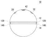
図1は、本発明の実施形態の第1の例であるボール状遊戯具10の正面概略図を示す。ボール状遊戯具10は、略球形であり、略半球状の2つのケーシングである第1ケーシング12,及び第2ケーシング14を備える。第1ケーシング12は、操作孔22、採音孔32、及び拡散孔42を有する。操作孔22からは、操作部20が、外部から操作可能に露出している。第1ケーシング12は、更に、採音孔32の内部に変換部を、拡散孔42の内部に再生部を、それぞれ内蔵する。
ボール状遊戯具10は、外部の音声を変換部を用いて電子信号に変換し、この電子信号に基づく音声データを、音声データの一例である第1音声データとして記録する。そして、キャッチボールやサッカー等に用いられる時に発生する衝撃を検知したとき、ボール状遊戯具10は、記録している第1音声データを、再生部を用いて再生し、音声を出す。
ボール状遊戯具10は、ユーザにより操作部20を操作されていることを条件に、外部の音声を記録する。操作部20は、例えばユーザが押下可能な押しボタンである。
【0012】
すなわち、ボール状遊戯具10は、任意の音声を吹き込んで再生することができるため、コミニュケーションツールとして用いられることができる。
また、サインボールの代わりとして用いることができる。すなわち、有名人に音声を吹き込んでもらうことで、ボール状遊戯具10は、記念品になることができる。
また、幼児向けの言語学習道具として用いられることができる。ここで、幼児の親の声を記録することで、親子間で用いられるコミニュケーションツールを兼ねることもできる。
【0013】
なお、ボール状遊戯具10の外形は、本図においては略球形であるが、多面体でもよく、また、多孔体としてもよい。すなわち、キャッチボールやキック等、球技に類似する遊技に用いることが可能な形状であればよい。
【0014】
また、第1ケーシング12の外周面の、第2ケーシング14に面する側の縁120は、全周にわたって内側に凹んでいる。これにより、第1ケーシング12と第2ケーシング14の合わせ目を完全に一致させる必要はなくなる。すなわち、必要となる加工精度を下げることで、より安価に第1ケーシング12及び第2ケーシング14を製造できる。
ここで、第2ケーシング14の外周面の、第1ケーシング12に面する側の縁140を、全周にわたって内側に凹ませてもよい。
【0015】
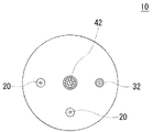
図2は、ボール状遊戯具10の上面概略図を示す。操作孔22、採音孔32、及び拡散孔42は、ボール状遊戯具10のケーシング上において、同一直線上にある。このレイアウトにすることで、操作孔22すなわち操作部20、採音孔32、及び拡散孔42の間に、ユーザがボール状遊戯具10を操作しやすくするために必要な相互間距離をとることができる。
また、拡散孔42は、操作孔22すなわち操作部20と採音孔32の間に位置する。これにより、操作部20の操作音は、変換部に採音されにくくなる。
また、採音孔32と操作孔22すなわち操作部20の距離を、1cm以上とするのが好ましい。これにより、変換部は操作部20の操作音を雑音として拾いにくくなる。さらに、ボール状遊戯具10が片手でもてる程度の大きさ、例えば直径7〜10cmの大きさである場合は、5cm以下とするのが好ましい。これにより、ユーザは片手でボール場遊戯具10を保持し、当該片手で操作部20を操作しながら採音孔32に音を容易に吹き込むことができる。
【0016】
図3は、ボール状遊戯具10の断面概略図を示す。本図は、第1ケーシング12と第2ケーシング14を分離して示す。
ボール状遊戯具10は、第1ケーシング12側に、操作部20、変換部30、再生部40、制御部50、及び電池100を有する。すなわち、ボール状遊戯具10の電子部品は、全て第1ケーシング12側に設けられる。従って、電子部品のレイアウト、及び制御部50の構造は簡単になる。
なお、操作部20は操作孔22すなわち凹部の中に、変換部30は採音孔32の中に、再生部40は拡散孔42の中に、それぞれ位置する。
【0017】
ここで、電池100は、第1ケーシング12の第2ケーシング14に対向する面121より第2ケーシング14側に位置している。このため、ユーザは、第1ケーシング12及び第2ケーシング14を分離させるのみで、電池100を交換可能状態にできる。なお、第2ケーシング14の第1ケーシング12に対向する面141は、第1ケーシング12の面121と比べ、電池100の突出分ほど内側に凹んでいる。従って、第1ケーシング12と第2ケーシング14を結合させたときに、電池100は面141に干渉しない。
【0018】
第1ケーシング12は、面121の外周縁近傍に、凸部122を有する。凸部122は円形に設けられる。この円は、第1ケーシング12の中心軸に対して同心である。すなわち、凸部122を設けることで、第1ケーシング12の縁120は、内側に向けて凹むことになる。
また、凸部122は、外周面の端部に、第1ケーシング12を第2ケーシング14に結合させるための雄ネジ部124を有する。すなわち、第1ケーシング12は、内面側に雄ネジ部124を有する。
【0019】
第2ケーシング14は、第1ケーシング12に対向する面142の外周縁近傍に、凸部142を有する。凸部142は、凸部122に対向するように設けられている。すなわち、凸部142を設けることで、第2ケーシング14の縁140は、内側に向けて凹むことになる。
また、凸部142は、内周面の端部に、雄ネジ部124に螺合する雌ネジ部144を有する。すなわち、第2ケーシング14は、内面側に雌ネジ部144を有する。雌ネジ部144と雄ネジ部124が螺合する事で、第1ケーシング12と第2ケーシングは互いに結合し、ボール状遊戯具10のケーシングを形成する。
【0020】
ところで、操作部20は、ユーザによって意識的に押し下げられるとき以外は用意に押し下げられない構成であることが好ましい。これにより、誤った録音が行われにくくなる。例えば、操作部20は、上記の如く、第1ケーシング12の表面よりも内部に凹んだ凹部である操作孔22に配置される。これにより、操作部20は第1ケーシング12の操作孔22近傍を有る程度変形させないと内部へ押し下げられないようになる。従って、例えばボール状遊戯具10が投げられた後に捕球されて第1ケーシング12へ衝撃が加わったとき、その衝撃力によって操作部20が押し下げられてしまうことを防止できる。
【0021】
図4は、ボール状遊戯具10の電子部品のブロック図を示す。ボール状遊戯具10は、電子部品として、操作部20、変換部30、再生部40、制御部50、及び電池100を備える。電池100は、再生部40、及び制御部50に必要な電力を供給する。また、制御部50は、信号送信部52、第1記録部54、検出部56、及び読み出し部58を有する。第1記録部54は、本発明に係る記録部の一例である。
【0022】
操作部20は、ユーザからの操作に従って、信号送信部52を動作させる。信号送信部52は、操作部20の物理的動作に従い、記録部54に動作信号を出力する。ここで、信号送信部52は例えば接点スイッチ又は圧電素子であり、操作部20は、接点スイッチの押しボタン、或いは圧電素子に圧力を伝達する押しボタンである。
【0023】
変換部30は、信号送信部52から動作信号を受信していることを条件に、外部の音声、例えばユーザが発する言葉を電子信号に変換し、第1記録部54に出力する。変換部30は、例えばマイクである。
【0024】
第1記録部54は、内部に書き換え可能な記録媒体を有する。第1記録部54は、変換部30から受信する電子信号に基づいた第1音声データを、内部の記録媒体に記録する。ここで、第1記録部54は、複数の第1音声データを互いに識別可能に記録してもよい。更に、第1記録部54は、必要に応じて記録媒体の第1音声データを上書きする。なお、第1記録部54は、補助電池を有しており、電池100の交換するときに、一定時間電力が供給されなくても、記録媒体内の記録が揮発しないようになっている。
【0025】
検出部56は、例えば振動センサであり、ボール状遊戯具10に加わる衝撃を検知し、読出部58に検知信号を出力する。検出部56の検知感度は、ボール状遊戯具10の使用目的によって適宜変更する。例えば、ボール状遊戯具10の対象ユーザを幼児とする場合は、落下距離5cm程度の衝撃を検知する感度を有することが好ましい。また、ボール状遊戯具10のユーザを小学生以上とする場合は、落下距離50cm以下の衝撃に対しては検知信号を出力しないようにするのが好ましい。
【0026】
読出部58は、検出部56から検知信号を受信すると、第1記録部54に格納されている第1音声データを読み出す。そして、検知信号を受信してから予め定められた時間が経過した後、再生部40に、読み出した第1音声データに基づく電子信号を出力する。ここで、予め定められた時間は、例えば0.1秒以上1秒以下である。ここで、読出部58は、第1音声データに基づく電子信号を増幅して出力してもよい。
【0027】
再生部40は、読出部58から受信した電子信号を音声に変換する。再生部40は、読出部58の動作により、衝撃が加わってから予め定められた時間遅延してから音声を発する。従って、再生音は、衝撃時に発生する音にかき消されにくくなる。ここで、再生部40は、受信した電子信号を増幅する機能を有してもよい。
【0028】
図5(A)は、検出部56の一例である衝撃センサの構成を示す。本例において、衝撃センサは、略円柱状の中空の収納部材200と、収納部材200の側面に設けられた第1電極210と、収納部材200の内部に、一面から起立している柱状の第2電極220とを有する。第2電極220の先端部は、第2電極220が慣性力の変化により折れ曲がりやすくなるように、重くすることが好ましい。
収納部材200は、絶縁体製である。第1電極210はリング状であり、収納部材200の内部に、露出している。ここで、第1電極210が露出している部分は、収納部材200の側面全周にわたるのが好ましい。第2電極220は、弾性を有しており、慣性力の変化を受けて弾性的に折れ曲がり、第1電極210に接する。すなわち、第1電極210と第2電極220が導通する事で、本衝撃センサは衝撃を検知する。
【0029】
図5(B)は、図5(A)に示す衝撃センサの変形例を示す。本例の衝撃センサは、柱状の第2電極220の代わりに、スプリング状の第2電極230を有する。本例の衝撃センサは、図5(A)に示す衝撃センサと同様の操作により、衝撃を検出する。
【0030】
図5(C)は、検出部56の他の例である振動センサの構成を示す。本例において、振動センサは、ベース部材201に圧電物質からなる歪みゲージ240を有する。本振動センサに衝撃が加わると、加えられた衝撃に従って圧電物質に歪みが生じ、この歪みに起因して圧電物質の中に起電力が生じる。本振動センサは、この電圧に基づいて、衝撃を検知する。ここで、圧電物質に生じる起電力の大きさは、衝撃の大きさによって異なる。従って、本振動センサを検出部56として用いると、ボール状遊戯具10に加わる衝撃の大きさを検知することができる。この場合、例えば衝撃の大きさに応じて再生する第1音声を変えることもできる。
【0031】
図6は、ボール状遊戯具10の動作の一例を示す。本例は、ボール状遊戯具10が、外部の音声を記録する時の動作の一例を示す。
信号送信部52が、操作部20へ加えられた操作を検知する(ステップS20:Yes)と、変換部30は、外部の音声を拾って電子信号に変換する(ステップS40)。第1記録部54は、変換部30から受信した電子信号に基づく第1音声データを記録する(ステップS60)。そして、第1記録部54は、操作部20への操作が行われている間(ステップS80:No)は、第1音声データを記録し続ける。そして、操作部20への操作が終了する(ステップS80:Yes)と、第1記録部54は、第1音声データの記録を終了する。
【0032】
図7は、ボール状遊戯具10の他の動作例を示す。本例は、ボール状遊戯具10が、第1音声データを再生する時の動作の一例を示す。
検出部56が衝撃を検知する(ステップS120:Yes)と、読出部58は、第1記録部54から第1音声データを読み出す(ステップS140)。そして、再生部40は、読み出された第1音声データに基づく電子信号を受信し、当該電子信号に基づいて音声を出すことで、第1音声データを再生する(ステップS160)。
【0033】
(第2の例)
図8は、本実施形態の第2の例であるボール状遊戯具10の平面概略図である。本図に示すように、本例において、ボール状遊戯具10は、第1の実施形態に係るボール状遊戯具10の外部構成に加え、外部に禁止スイッチ70を更に備える。禁止スイッチ70は、本発明に係る禁止部の一例であり、外部から操作可能である。禁止スイッチ70と操作部20との間には、拡散孔42など他の構成要素が存在する。この配置にすることで、ユーザーが、操作部20を操作するときに禁止スイッチ70を誤って操作する可能性は低くなる。
【0034】
図9は、本例のボール状遊戯具10の電子部品の構成を示す。本図に示す構成は、図4に示す構成と概略同じであるが、第2記録部60及び禁止スイッチ70を更に備える点で異なる。すなわち、本例においては、記録部として、第1記録部54及び第2記録部60を備える。
【0035】
第2記録部60は、内部に書き換え不可である記録媒体を有する。この記録媒体には、予め第2音声データが格納されており、読出部58からの要求に応じて、内部の第2音声データを読出部58に提供する。ここで、第2音声データは、例えば、有名人の音声データなどの、記念的な意味合いを持つ音声データである。
【0036】
禁止スイッチ70は、信号送信部52の動作を禁止したり、許可したりするスイッチである。禁止スイッチ70によって動作が禁止されている場合、信号送信部52は、操作部20の操作にかかわらず第1記録部54に信号を送信しない。
従って、ボール状遊戯具10を使用している時にユーザが誤って操作部20を操作しても、第1記録部54の第1音声データが誤って上書きされることはない。
なお、本図において、禁止スイッチ70は、信号送信部52に動作禁止信号を送信する形態になっているが、信号送信部52と第1記録部54の接続を物理的にON/OFFする構成としてもよい。また、禁止スイッチ70は、スライド式のスイッチでもよいし、押しボタン式のスイッチでもよい、
【0037】
また、禁止スイッチ70は、信号送信部52の動作を禁止している場合、読出部58に信号を送信する。読出部58は、禁止スイッチ70から信号を受信している間は、第1記録部54の第1音声データを読み出さずに、第2記録部60の第2音声データを読み出し、第2音声データに基づく電子信号を再生部40に出力する。
【0038】
図10は、本例に係るボール状遊戯具10の録音時の動作の一例を示す。
信号送信部52が、操作部20へ加えられた操作を検知し(ステップS20:Yes)かつ、禁止スイッチ70が録音を許可している場合(ステップS21:Yes)のみ、変換部30は、外部の音声を拾って電子信号に変換する(ステップS40)。そして、第1記録部54は、変換部30から受信した電子信号に基づく第1音声データを記録する(ステップS60)。その後の動作は、図6に示す第1の実施形態と同様であるので、省略する。
【0039】
図11は、本例に係るボール状遊戯具10の他の動作例を示す。本例は、ボール状遊戯具10が、第1音声データを再生する時の動作の一例を示す。
検出部56が衝撃を検知する(ステップS120:Yes)と、読出部58は、禁止スイッチ70が録音を許可しているか否かを確認する(ステップS130)。録音を許可している場合、読出部58は、第1記録部54から第1音声データを読み出す(ステップS142)。録音を許可していない場合、読出部58は、第2記録部54から第2音声データを読み出す(ステップS144)。そして、再生部40は、読み出された第1音声データ又は第2音声データに基づく電子信号を受信し、電子信号に基づいて音声を出すことで、第1音声データ又は第2音声データを再生する(ステップS160)。
従って、本実施形態によれば、ボール状遊戯具10の楽しみ方がさらに増える。
【0040】
(第3の例)
図12は、本実施形態の第3の例に係るボール状遊戯具の電子部品の構成を示す。本図に示す構成は、図4に示す構成と概略同じであるが、選択スイッチ72を更に備える点で異なる。選択スイッチ72は、本発明に係る指示部の一例である。なお、選択スイッチ72は、第2の例における禁止スイッチ70と同様に、外部から操作可能である。選択スイッチ72と操作部20との間には、拡散孔42など他の構成要素が存在する。
【0041】
選択スイッチ72は、第1記録部54及び読出部58に、選択信号を受信する。すなわち、第1記録部54は、複数の第1音声データの各々を、選択スイッチ72からの選択信号に対応させて記録する。ここで、第1記録部54は、例えば各選択信号に対応した記録領域に、第1音声データを記録する。読出部58は、選択スイッチ72からの選択信号に対応する第1音声データを、第1記録部54から読み出し、第1音声データに基づく電子信号を再生部40に出力する。
【0042】
図13は、本例に係るボール状遊戯具10の動作の一例を示す。本例は、ボール状遊戯具10の録音時の動作を示す。
信号送信部52が、操作部20へ加えられた操作を検知する(ステップS20:Yes)と、変換部30は、外部の音声を拾って電子信号に変換する(ステップS40)。第1記録部54は、変換部30から受信した電子信号に基づく第1音声データを、選択スイッチ72による選択に対応付けて記録する(ステップS62)。以後の動作は、第1の例と同様であるので、詳細は省略する。
【0043】
図14は、本例に係るボール状遊戯具10の他の動作例を示す。本例は、ボール状遊戯具10が、第1音声データを再生する時の動作の一例を示す。
検出部56が衝撃を検知する(ステップS120:Yes)と、読出部58は、選択スイッチによる選択を確認する(ステップS122)。そして、読出部58は、選択スイッチによる選択に対応する第1音声データを、第1記録部54から読み出す(ステップS124)。そして、再生部40は、読み出された第1音声データに基づく電子信号を受信し、当該電子信号に基づいて音声を出すことで、第1音声データを再生する(ステップS160)。
【0044】
従って、本例によれば、ユーザは、複数の音声をボール状遊戯具10に記録できる。また、ユーザは、ボール状遊戯具10において、所望の音声を選択して再生できる。すなわち、本例のボール状遊戯具10は、より多くの楽しみ方をユーザに提供できる。
【0045】
(第4の例)
図15は、本実施形態の第4の例に係るボール状遊戯具10の平面概略図である。本例において、ボール状遊戯具10は、第1の例に係るボール状遊戯具10と概略同じ構成であるが、操作部20を複数備える点が異なる。複数の操作部20は、互いに離れた位置に設けられるのが好ましい。例えば、本図に示すように、拡散孔42を中心に90°異なる位置に設ける。この配置にすることで、ユーザが、誤って複数の操作部20を予め定められた時間内に操作する可能性は低くなる。
【0046】
図16は、本例に係るボール状遊戯具10の録音時の動作を示す。信号送信部52が、一の操作部20へ操作が加えられてから、予め定められた時間以内に、他の操舵部20への操作を検知する(ステップS22)と、変換部30は、外部の音声を拾って電子信号に変換する(ステップS40)。その後の動作は、図6に示す第1の例と同様であるので、省略する。なお、ステップS42における予め定められた時間は、0を含む。すなわち、複数の操作部20が同時に操作されることを、第1音声データが記録されるための条件としてもよい。
従って、ボール状遊戯具10を使用している時にユーザが誤って一の操作部20を操作しても、第1記録部54の第1音声データが誤って上書きされることはない。
【0047】
なお、本実施形態に係るボール状遊戯具10の再生時の動作は、第1の実施形態に係るボール状遊戯具10の再生時の動作と同じであるため、説明を省略する。
【0048】
(第5の例)
図17は、本実施形態の第5の例に係るボール状遊戯具10の断面概略図を示す。本例において、ボール状遊戯具10は、第1の例として示した構成に加え、被覆部24を備える。被覆部24は、例えば樹脂製であり、操作部20を有する操作孔22を取り外し可能に覆う。従って、ユーザは、操作部20を操作する意志がない時は、被覆部24で操作孔22を覆うことで、操作部20を誤操作することを防ぐことができる。
なお、本例において、被覆部24を、取り外し可能な形態としたが、スライドさせることで、操作孔22を覆ったり開放したりできる構成としてもよい。
【0049】
(第6の例)
第6の例において、ボール状遊戯具10の構成は、第1の例と同様の構成であるが、録音時の動作が異なる。
【0050】
図18は、本例に係るボール状遊戯具10の録音時の動作例を示す。
本例において、信号送信部52が、操作部20への操作が一定時間継続していることを検知する(ステップS24)と、変換部30は、外部の音声を拾って電子信号に変換する(ステップS40)。そして、第1記録部54は、変換部30から受信した電子信号に基づく第1音声データを、予め定められた時間ほど記録する(ステップS64)。
本例において、第1記録部54は、操作部20への動作が一定時間継続しないと第1音声データを記録しない。従って、ボール状遊戯具10を使用している時にユーザが誤って操作部20を操作しても、第1記録部54の第1音声データが誤って上書きされる可能性は低くなる。
なお、本例においても、第1記録部54は、第1音声データの記録を開始した後、操作部20へ操作されていることを条件に第1音声データの記録を継続する構成としてもよい。
【0051】
(第7の例)
第7の例において、ボール状遊戯具10の構成は、制御部50の構成を除き、第1の例で示した構成と同じである。
【0052】
図19は、本例に係るボール状遊戯具10の、制御部50の構成を示す。本例は、第1の例における制御部50の構成と概略同じであるが、第1記録部54と読み出し部58の間に選択部62を有する点で異なる。また、第1記録部54には、複数の第1音声データが格納されている。
選択部62は、読出部58から第1音声データの読み出し命令を受信すると、第1記録部54に格納されている複数の第1音声データから、任意の第1音声データを選択し、読み出す。そして、読み出した第1音声データを読出部58に出力する。
ここで、選択部62は、複数の第1音声データのうちの少なくとも2つを、互いに異なる確率で選択してもよい。例えば、「当たり」と「外れ」のうち、当たりをより高い確率で選んでもよい。
【0053】
図20は、本例に係るボール状遊戯具10の再生時の動作を示す。
検出部56が衝撃を検知する(ステップS120:Yes)と、読出部58は、選択部62に読み出し命令を出力する(ステップS152)。選択部62は第1記録部54からランダムに第1音声データを選択する(ステップS154)。読出部58は、選択部62を介して、選択部62により選択された第1音声データを取得する(ステップS156)。そして、再生部40は、読み出された第1音声データに基づく電子信号を受信し、当該電子信号に基づいて音声を出すことで、第1音声データを再生する(ステップS160)。
【0054】
従って、本例によれば、どの第1音声データが再生されるかは、ユーザには分からない。従って、ボール状遊戯具10による楽しみが更に増す。また、少なくとも2つの第1音声データを、互いに異なる確率で選択する構成とすることで、より楽しみが増す。
【0055】
(第8の例)
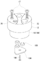
図21は、第8の例に係るボール状遊戯具10の斜視概略図である。本例において、ボール状遊戯具10は、ケーシングの構成を除き、第1の例と同じ構成を取る。ボール状遊戯具10のケーシングの大部分は第2ケーシング14が占める。第1ケーシング12は、第2ケーシング14に押し込まれる構成となっている。第1ケーシング12を第2ケーシング14に固定する際、図示しないネジを用いてもよい。
本例の構成とすると、例えば野球の硬式ボールなど、第1ケーシング12及び第2ケーシング14の少なくとも一方がねじ切りできない素材により構成されていても、第1ケーシング12及び第2ケーシング14を互いに固定することができる。
【0056】
また、本例において、第1ケーシング12は、ネジ17によって第2ケーシング14に固定される。より詳細には、ネジ17は、外側から第1ケーシング12を貫通する。また、第2ケーシング14の開口部には、部材300が填め込み固定されている。部材300は、ネジ17に螺合するネジ穴302を有する。すなわち、ネジ17がネジ穴302に螺合する事で、第1ケーシング12は第2ケーシング14に固定される。従って、ネジ17を外すことで、第1ケーシング12を第2ケーシング14から簡単に取り外すことができる。第1ケーシング12を取り外すことで、制御部50等の内部部品の点検を容易に行える。
【0057】
また、本例において、部材300は、ケーシング102が填め込まれるように、例えば円筒状の中空構造となっている。ここで、部材300の外壁304は、一部に、内周側に出っ張っている凸部306を有する。
さらに、ケーシング102の一部は、凸部306が填り込むための凹部103を有する。すなわち、凸部306が凹部103に填り込むことで、第1ケーシング12と第2ケーシング14の相対位置は容易に決定される。従って、容易に第1ケーシング12を第2ケーシング14に取り付けられる。
【0058】
また、本例において、第1ケーシング12の少なくとも操作部20の周囲は、ポリウレタン、スポンジ等の弾性体からなる。操作部20は、押下型のスイッチであり、操作孔22すなわち第1ケーシング12の表面よりも内部に凹んだ凹部の中に配置されている。これにより、操作部20は第1ケーシング12における操作孔22近傍をある程度変形させないと内部へ押し下げられない。すなわち、操作部20は衝撃によっては容易に押し下げられないようになっている。従って、例えばボール状遊戯具10が投げられた後に捕球されることで、第1ケーシング12に衝撃が加わった場合に、その衝撃力によって操作部20が押し下げられてしまうことを防止できる。
ここで、操作孔22の径を、人の指が入らない程度、例えば3mm〜8mm程度にしてもよい。この際、操作孔22の頂部をすり鉢状に広げ、指が填りやすくしてもよい。
【0059】
図22は、第1ケーシング12及びケーシング102の一部分解図である。本図に示すように、電池100は、ケーシング102の一面104を取り外すことにより、外部に露出する。従って、ユーザは、電池100を簡単に交換できる。ここで、一面104は、ケーシング102にネジ106で固定される。これにより、ボール状遊技具10に衝撃が加わっても、電池100が接触不良となる可能性は低くなる。なお、ネジ106を挿入する為に裏蓋104に設けられる穴は、一面104の中心若しくはその近傍に設けられるのが好ましい。また、ネジ106に対応してケーシング102に設けられるネジ穴も、一面104の中心若しくはその近傍に対応する箇所に設けられるのが好ましい。これにより、ネジ106を複数用いる必要はなくなる。ここで、電池100を複数設ける場合は、電池100をネジ106を中心に同心状に配列するのが好ましい。なお、本図において、凹部103は図示を省略している。
【0060】
図23は、本例における第1ケーシング12の断面概略図である。本図において、操作孔22の頂部26はすり鉢状に広がっている。また、操作部20の頭部は、操作孔22の頂部26の下端より下にある。これにより、ユーザが、意図せずに操作部20を操作する可能性は低くなる。
【0061】
以上、本発明を実施形態を用いて説明したが、本発明の技術的範囲は上記実施形態に記載の範囲には限定されない。上記実施形態に、多様な変更または改良を加えることができる。例えば、上述した各例の特徴的な構成要素を任意に組み合わせることができる。そのような変更または改良を加えた形態も本発明の技術的範囲に含まれ得ることが、特許請求の範囲の記載から明らかである。
【0062】
例えば、第1の例において、読出部58が、検出部56から検知信号を受信してから予め定められた時間が経過した後、第1音声データに基づく電子信号を再生部40に出力していたが、この構成の代わりに以下の構成としてもよい。すなわち、読出部58は検知信号受信後すぐに第1音声データに基づく電子信号を再生部40に出力する。再生部40は、電子信号を受信してから予め定められた時間が経過した後に電子信号を音声に変換する。
【0063】
また、音声データを再生している最中に検出部56が新たな衝撃を検出した場合は、当該衝撃の検出を無効としてもよいし、有効としてもよい。有効とする場合、再生部40は、衝撃を検出するたびに、第1音声データの再生を最初から行う。
【0064】
また、第2の例において、禁止スイッチ70は、信号送信部52の動作を禁止することで、第1記録部54の動作を禁止する構成としたが、禁止スイッチ70が、第1記録部54、又は変換部30の動作を直接禁止する構成としてもよい。
【0065】
また、上記実施形態において、変換部30が動作信号を受信することを条件に動作する構成としたが、変換部30ではなく、第1記録部54が動作信号を受信することを条件に動作する構成としてもよい。また、変換部30及び第1記録部54が動作信号を受信することを条件に動作する構成としてもよい。
【0066】
さらに、複数の音声データを同時に読み出し、これらの複数の音声データを合成した音声を出力してもよい。この場合、例えば第1音声データのみを複数読み出してもよいし、第2音声データのみを複数読み出してもよいし、第1音声データ及び第2音声データを複数読み出してもよい。
【0067】
また、上記実施形態から、以下の技術が開示されていることが明らかである。項目1 衝撃に応じて音声を出すボール状遊戯具であって、外部の音声を電子信号に変換する変換部と、前記電子信号に基づく音声データを記録する記録部と、前記ボール状遊戯具に加わる衝撃を検知する検出部と、前記検出部が衝撃を検知したときに前記記録部に記録されている前記音声データに基づいて音声を出す再生部と、ボール状遊戯具の電源となる電池と、前記変換部、前記第1記録部、前記検出部、前記再生部、及び前記電池を内部に格納するケーシングを更に備え、前記ケーシングは、前記電池を外部から取り替え可能に内面側に保持する第1ケーシングと、前記第1ケーシングと共に当該ケーシングを形成するする第2ケーシングとを有することを特徴とするボール状遊戯具。
項目2 前記第1ケーシングは、前記ケーシングの中心軸を中心に設けられた螺旋状の雌ネジ部又は雄ネジ部の一方を内面側に含み、前記第2ケーシングは、前記第1ケーシングの前記雌ネジ部又は雄ネジ部の一方に螺合するように、前記中心軸を中心に設けられた螺旋状の雌ネジ部又は雄ネジ部の他方を内面側に含むことを特徴とする項目1に記載のボール状遊戯具。
項目3 前記第1ケーシング及び前記第2ケーシングの少なくとも一方の外周面の、他方に面する側の縁は、全周にわたって内側に凹んでいることを特徴とする項目1に記載のボール状遊戯具。
【0068】
【発明の効果】
上記説明から明らかなように、本発明によれば、従来より楽しみ方を増やした、衝撃に応じて音声を出すボール状遊戯具を提供することができる。
【図面の簡単な説明】
【図1】本発明の実施形態の第1の例であるボール状遊戯具10の正面概略図を示す。
【図2】ボール状遊戯具10の上面概略図を示す。
【図3】ボール状遊戯具10の断面概略図を示す。
【図4】ボール状遊戯具10の電子部品のブロック図を示す。
【図5】(A)及び(B)は、検出部56の一例である衝撃センサの構成を示し、(C)は、検出部56の他の例である振動センサの構成を示す。
【図6】ボール状遊戯具10の動作の一例を示す。
【図7】ボール状遊戯具10の他の動作例を示す。
【図8】第2の例であるボール状遊戯具10の平面概略図を示す。
【図9】第2の例に係るボール状遊戯具10の電子部品の構成を示す。
【図10】第2の例に係るボール状遊戯具10の録音時の動作の一例を示す。
【図11】第2の例に係るボール状遊戯具10の他の動作例を示す。
【図12】第3の例に係るボール状遊戯具の電子部品の構成を示す。
【図13】第3の例に係るボール状遊戯具10の動作の一例を示す。
【図14】第3の例に係るボール状遊戯具10の他の動作例を示す。
【図15】第4の例に係るボール状遊戯具10の平面概略図である。
【図16】第4の例に係るボール状遊戯具10の録音時の動作を示す。
【図17】第5の例に係るボール状遊戯具10の断面概略図を示す。
【図18】第6の例に係るボール状遊戯具10の録音時の動作例を示す。
【図19】第7の例に係るボール状遊戯具10の、制御部50の構成を示す。
【図20】第7の例に係るボール状遊戯具10の再生時の動作を示す。
【図21】第8の例に係るボール状遊戯具10の斜視概略図である。
【図22】第8の例に係る第1ケーシング12及びケーシング102の一部分解図である。
【図23】第8の例に係る第1ケーシング12の断面概略図である。
【符号の説明】
10 ボール状遊戯具
12 第1ケーシング
120 縁
124 雄ネジ部
14 第2ケーシング
140 縁
144 雌ネジ部
20 操作部
30 変換部
40 再生部
52 信号送信部
54 第1記録部
56 検出部
58 読み出し部
60 第2記録部
70 禁止スイッチ
72 選択スイッチ
100 電池[0001]
TECHNICAL FIELD OF THE INVENTION
The present invention relates to a ball-shaped play equipment. In particular, the present invention relates to a ball-shaped play equipment that has an increased number of ways of enjoyment and emits sound in response to an impact.
[0002]
[Prior art]
With respect to a ball-shaped play equipment that generates a sound upon detecting an impact, for example, a technique disclosed in Japanese Patent Application Laid-Open No. 2-154777, a technique disclosed in Japanese Utility Model Application Laid-Open No. 50-892, and a Japanese Utility Model Application Laid-Open No. 6-34660. There is a technique disclosed in a gazette. As for a ball-shaped play equipment that generates light by detecting an impact, there is a technique disclosed in Japanese Utility Model Registration Application No. 3025968.
[0003]
[Problems to be solved by the invention]
According to the conventional technique, only a predetermined sound can be emitted. Therefore, there were restrictions on how to enjoy.
[0004]
Therefore, an object of the present invention is to provide a ball-shaped play equipment that can solve the above-mentioned problems. This object is achieved by a combination of features described in the independent claims. The dependent claims define further advantageous embodiments of the present invention.
[0005]
[Means for Solving the Problems]
That is, according to the first embodiment of the present invention, there is provided a ball-shaped play equipment that outputs sound in response to an impact, a conversion unit that converts external sound into an electronic signal, and a recording unit that records sound data based on the electronic signal. And a detecting unit for detecting an impact applied to the ball-shaped play equipment, and a reproducing unit for outputting a sound based on audio data recorded in the recording unit when the detecting unit detects the impact. And a ball-shaped play equipment.
[0006]
In the above aspect, at least one of the conversion unit and the recording unit operates on the condition that an operation signal is received, and further, an operation unit that can be operated from the outside, and the conversion unit or the operation signal according to an operation applied to the operation unit. A signal transmission unit for transmitting to at least one of the recording units may be provided.
In this case, a prohibition unit that prohibits at least one operation of the conversion unit and the recording unit regardless of an operation applied to the operation unit may be further provided. Further, in this case, the recording unit has a first recording unit that stores first audio data that is audio data based on an electronic signal, and a second recording unit that holds second audio data in advance. If the detection unit detects an impact while the switch prohibits the operation of the signal transmission unit, the detection unit acquires the second audio data stored in the second recording unit, and outputs the audio based on the second audio data. May be issued.
Further, the electronic apparatus may further include a casing in which the conversion unit, the recording unit, the detection unit, and the reproduction unit are stored. Further, at least one of the conversion unit and the recording unit may continuously receive the operation signal for a predetermined time or more. Also, a plurality of operation units are provided, and the signal transmission unit transmits an operation signal by operating at least one other operation unit within a predetermined time after one operation unit is operated. You may. Further, a cover may be provided which is detachable or movable and covers the operation unit of the signal transmission unit to disable operation from outside. Further, the operation unit is further provided with a casing made of an elastic material, at least a part of which is stored in the inside, and the operation unit is a push-type switch, and is located at a position where it can be pressed from the outside via the elastic body portion of the casing. It may be arranged.
The conversion unit, the recording unit, the detection unit, the playback unit, and a casing for storing the battery therein, the casing is provided with a sound collection hole for facilitating the collection of sound by the conversion unit, and an external sound from the playback unit. In addition to having a diffusion hole for facilitating diffusion of the sound, the operation unit may be disposed at a position substantially along a straight line connecting the sound collection hole and the diffusion hole. In this case, the diffusion hole is preferably located between the sound collection hole and the operation unit. In addition, the sound collection hole is preferably located at a distance of 1 cm or more from the operation unit on the casing.
[0007]
Further, in the above aspect, the recording unit stores the plurality of audio data so as to be identifiable from each other, and is further operable from outside, and determines which of the plurality of audio data to acquire based on an operation from outside. An instructing unit for instructing the reproducing unit may be further provided.
Further, in the above embodiment, the recording unit further stores a plurality of audio data, and each time the processing by the reproduction unit, further includes a selection unit that randomly selects any of the plurality of audio data, the reproduction unit, The sound may be output based on the sound data selected by the unit. In this case, the selection unit may select at least two of the plurality of audio data with different probabilities.
Further, in the above embodiment, the reproducing unit may output a sound based on the sound data after a predetermined time has elapsed after the detecting unit detects the impact. In this case, the specific time is preferably 0.1 seconds or more and 1 second or less.
[0008]
According to a second aspect of the present invention, there is provided a ball-shaped play equipment characterized in that an external sound is recorded and the recorded sound is reproduced when an impact is applied.
In the above embodiment, an external voice may be recorded according to a user operation. Further, while the user is operating, the external sound may be continuously recorded. Recording of external sound may be selectively prohibited. The sound recorded after a predetermined time delay from the impact may be reproduced.
[0009]
Note that the above summary of the present invention does not list all of the necessary features of the present invention, and a sub-combination of these features may also be an invention.
[0010]
BEST MODE FOR CARRYING OUT THE INVENTION
Hereinafter, the present invention will be described through embodiments of the present invention. However, the following embodiments do not limit the claimed invention, and all combinations of the features described in the embodiments are solutions of the present invention. Is not always required.
[0011]
(First example)
FIG. 1 is a schematic front view of a ball-
The ball-shaped
The ball-shaped
[0012]
That is, the ball-shaped
Also, it can be used as a substitute for a sign ball. In other words, the ball-shaped
It can also be used as a language learning tool for infants. Here, by recording the voice of the parent of the infant, it can also serve as a communication tool used between the parent and child.
[0013]
Although the outer shape of the ball-shaped
[0014]
An
Here, the
[0015]
FIG. 2 is a schematic top view of the ball-shaped
The
Further, it is preferable that the distance between the
[0016]
FIG. 3 is a schematic cross-sectional view of the ball-shaped
The ball-shaped
The
[0017]
Here, the
[0018]
The
The
[0019]
The
Further, the
[0020]
By the way, it is preferable that the
[0021]
FIG. 4 shows a block diagram of the electronic components of the ball-shaped
[0022]
The
[0023]
The
[0024]
The
[0025]
The
[0026]
When receiving the detection signal from the
[0027]
The reproducing
[0028]
FIG. 5A illustrates a configuration of an impact sensor that is an example of the
The
[0029]
FIG. 5B shows a modification of the impact sensor shown in FIG. The impact sensor of this example has a spring-shaped
[0030]
FIG. 5C illustrates a configuration of a vibration sensor that is another example of the
[0031]
FIG. 6 shows an example of the operation of the ball-shaped
When the
[0032]
FIG. 7 shows another operation example of the ball-shaped
When the detecting
[0033]
(Second example)
FIG. 8 is a schematic plan view of a ball-shaped
[0034]
FIG. 9 shows the configuration of electronic components of the ball-shaped
[0035]
The
[0036]
The
Therefore, even if the user operates the
In this figure, the
[0037]
The
[0038]
FIG. 10 shows an example of an operation at the time of recording of the ball-shaped
Only when the
[0039]
FIG. 11 shows another operation example of the ball-shaped
When the detecting
Therefore, according to this embodiment, the way of enjoying the ball-shaped
[0040]
(Third example)
FIG. 12 shows a configuration of an electronic component of a ball-shaped play equipment according to a third example of the present embodiment. The configuration shown in this figure is substantially the same as the configuration shown in FIG. 4, except that the configuration further includes a selection switch 72. The selection switch 72 is an example of an instruction unit according to the present invention. The selection switch 72 can be operated from the outside similarly to the
[0041]
The selection switch 72 receives a selection signal in the
[0042]
FIG. 13 shows an example of the operation of the ball-shaped
When the
[0043]
FIG. 14 shows another operation example of the ball-shaped
When the detecting
[0044]
Therefore, according to this example, the user can record a plurality of sounds on the ball-shaped
[0045]
(Fourth example)
FIG. 15 is a schematic plan view of a ball-shaped
[0046]
FIG. 16 shows an operation during recording of the ball-shaped
Therefore, even if the user erroneously operates one
[0047]
The operation at the time of reproduction of the ball-shaped
[0048]
(Fifth example)
FIG. 17 is a schematic sectional view of a ball-shaped
In the present example, the covering
[0049]
(Sixth example)
In the sixth example, the configuration of the ball-shaped
[0050]
FIG. 18 shows an operation example of the ball-shaped
In this example, when the
In this example, the
Also in this example, the
[0051]
(Seventh example)
In the seventh example, the configuration of the ball-shaped
[0052]
FIG. 19 shows the configuration of the
Upon receiving the command to read out the first audio data from the
Here, the
[0053]
FIG. 20 shows an operation at the time of reproduction of the ball-shaped
When the detecting
[0054]
Therefore, according to this example, the user does not know which first audio data is reproduced. Accordingly, the enjoyment of the ball-shaped
[0055]
(Eighth example)
FIG. 21 is a schematic perspective view of the ball-shaped
With the configuration of the present example, the
[0056]
In the present example, the
[0057]
In the present example, the
Further, a part of the
[0058]
In the present example, at least the periphery of the
Here, the diameter of the
[0059]
FIG. 22 is a partially exploded view of the
[0060]
FIG. 23 is a schematic sectional view of the
[0061]
As described above, the present invention has been described using the embodiment. However, the technical scope of the present invention is not limited to the scope described in the embodiment. Various changes or improvements can be added to the above embodiment. For example, the characteristic components of each example described above can be arbitrarily combined. It is apparent from the description of the appended claims that embodiments with such changes or improvements can be included in the technical scope of the present invention.
[0062]
For example, in the first example, the
[0063]
Further, when the
[0064]
In the second example, the
[0065]
In the above-described embodiment, the operation is performed on the condition that the
[0066]
Further, a plurality of audio data may be read out at the same time, and an audio synthesized from the plurality of audio data may be output. In this case, for example, a plurality of only the first audio data may be read, a plurality of the second audio data alone may be read, or a plurality of the first audio data and the second audio data may be read.
[0067]
It is apparent from the above embodiment that the following technology is disclosed. Item 1 is a ball-shaped plaything that outputs sound in response to an impact, wherein the conversion section converts external sound into an electronic signal, a recording section that records sound data based on the electronic signal, and the ball-shaped plaything. A detecting unit for detecting an applied shock, a reproducing unit for outputting a sound based on the sound data recorded in the recording unit when the detecting unit detects the shock, and a battery serving as a power supply for the ball-shaped play equipment. A conversion unit, the first recording unit, the detection unit, the reproduction unit, and a casing for storing the battery inside, the casing is configured to hold the battery on the inner surface side so as to be replaceable from the outside. A ball-shaped play equipment comprising: a first casing; and a second casing that forms the casing together with the first casing.
Item 2 The first casing includes, on an inner surface side, one of a spiral female screw portion or a male screw portion provided around a central axis of the casing, and the second casing includes the female member of the first casing. Item 1 is characterized by including the other of a helical female screw portion or a male screw portion provided on the center axis so as to be screwed to one of the screw portion and the male screw portion on the inner surface side. Ball-shaped play equipment.
Item 3 An edge of at least one of the outer peripheral surfaces of the first casing and the second casing on the side facing the other side is inwardly depressed over the entire circumference, and the ball-shaped play equipment according to Item 1 is provided. .
[0068]
【The invention's effect】
As is apparent from the above description, according to the present invention, it is possible to provide a ball-shaped play equipment that has a greater number of ways of enjoying than before and that emits sound in response to an impact.
[Brief description of the drawings]
FIG. 1 is a schematic front view of a ball-shaped
FIG. 2 shows a schematic top view of the ball-shaped
3 is a schematic cross-sectional view of the ball-shaped
4 shows a block diagram of electronic components of the ball-shaped
FIGS. 5A and 5B show a configuration of an impact sensor which is an example of the
6 shows an example of the operation of the ball-shaped
FIG. 7 shows another operation example of the ball-shaped
FIG. 8 is a schematic plan view of a ball-shaped
FIG. 9 shows a configuration of an electronic component of the ball-shaped
FIG. 10 shows an example of an operation during recording of the ball-shaped
FIG. 11 shows another operation example of the ball-shaped
FIG. 12 shows a configuration of an electronic component of a ball-shaped play equipment according to a third example.
FIG. 13 shows an example of the operation of the ball-shaped
FIG. 14 shows another operation example of the ball-shaped
FIG. 15 is a schematic plan view of a ball-shaped
FIG. 16 shows an operation during recording of the ball-shaped
FIG. 17 is a schematic cross-sectional view of a ball-shaped
FIG. 18 shows an operation example during recording of the ball-shaped
FIG. 19 shows a configuration of a
FIG. 20 shows an operation at the time of reproduction of the ball-shaped
FIG. 21 is a schematic perspective view of a ball-shaped
FIG. 22 is a partially exploded view of a
FIG. 23 is a schematic sectional view of a
[Explanation of symbols]
10 Ball-shaped play equipment
12 First casing
120 rim
124 Male thread
14 Second casing
140 rim
144 female thread
20 Operation section
30 Conversion unit
40 playback unit
52 signal transmission unit
54 First Recording Unit
56 detector
58 Readout unit
60 Second Recording Unit
70 Prohibition switch
72 Selection switch
100 batteries
Claims (13)
外部の音声を電子信号に変換する変換部と、
前記電子信号に基づく音声データを記録する記録部と、
前記ボール状遊戯具に加わる衝撃を検知する検出部と、
前記検出部が衝撃を検知したときに前記記録部に記録されている前記音声データに基づいて音声を出す再生部と、
前記変換部、前記記録部、前記検出部、及び前記再生部を内蔵するケーシングと、
前記ケーシングに設けられた孔と、
前記孔の周囲において前記ケーシングの少なくとも一部を構成する弾性体と、
前記孔の中に配置され、前記孔の周囲の弾性体を変形させることで操作される、押下型のスイッチと、
前記押下型のスイッチへ加えられる操作に従って動作信号を前記変換部又は前記記録部の少なくとも一方に送信する信号送信部と
を備え、
前記変換部及び前記記録部の少なくとも一方は、前記動作信号を受信することを条件に動作し、
前記信号送信部の動作を、前記押下型のスイッチへ加えられる操作にかかわらず禁止する禁止部を更に備え、
前記記録部は、前記電子信号に基づく音声データである第1音声データを格納する第1記録部と、予め第2音声データを保持する第2記録部を有し、
前記再生部は、前記禁止部が前記信号送信部の動作を禁止している間に前記検出部が衝撃を検知した場合は、前記第2記録部に保持されている第2音声データを取得し、前記第2音声データに基づいて音声を出すボール状遊戯具。 A ball-shaped play equipment that produces sound in response to an impact,
A converter for converting external sound into an electronic signal;
A recording unit that records audio data based on the electronic signal,
A detection unit that detects an impact applied to the ball-shaped play equipment,
A playback unit that outputs a sound based on the sound data recorded in the recording unit when the detection unit detects an impact,
A casing containing the conversion unit, the recording unit, the detection unit, and the reproduction unit;
A hole provided in the casing,
An elastic body constituting at least a part of the casing around the hole,
A push-type switch that is arranged in the hole and operated by deforming an elastic body around the hole,
A signal transmission unit that transmits an operation signal to at least one of the conversion unit or the recording unit according to an operation applied to the push-type switch;
With
At least one of the conversion unit and the recording unit operates on condition that the operation signal is received,
Further comprising a prohibition unit for prohibiting the operation of the signal transmission unit regardless of the operation applied to the push-type switch,
The recording unit has a first recording unit that stores first audio data that is audio data based on the electronic signal, and a second recording unit that holds second audio data in advance,
The reproducing unit acquires the second audio data held in the second recording unit when the detecting unit detects an impact while the prohibiting unit prohibits the operation of the signal transmitting unit. And a ball-shaped play equipment that produces a sound based on the second sound data.
前記信号送信部は、一の前記押下型のスイッチが操作された後、予め定められた時間内に、他の少なくとも一つの前記押下型のスイッチが操作されることで、前記動作信号を送信することを特徴とする請求項1に記載のボール状遊戯具。A plurality of the push-type switches,
The signal transmission unit transmits the operation signal by operating at least one other of the push-type switches within a predetermined time after one push-type switch is operated. The ball-shaped play equipment according to claim 1, characterized in that:
更に、外部から操作可能であり、前記複数の音声データのいずれを取得するかを、外部からの操作に基づいて前記再生部に指示する指示部を更に備えることを特徴とする請求項1に記載のボール状遊戯具。The recording unit stores a plurality of the audio data so as to be identifiable from each other,
2. The apparatus according to claim 1, further comprising an instruction unit that can be operated from the outside and instructs the reproduction unit on which of the plurality of audio data to acquire based on an operation from the outside. Ball-shaped play equipment.
前記再生部による処理の度に、前記複数の音声データのいずれかをランダムに選択する選択部を更に備え、
前記再生部は、前記選択部が選択した前記音声データに基づいて音声を出すことを特徴とする請求項1に記載のボール状遊戯具。The recording unit stores a plurality of audio data,
Each time the processing by the playback unit, further comprises a selection unit that randomly selects any of the plurality of audio data,
2. The ball-shaped play equipment according to claim 1, wherein the playback unit outputs a sound based on the sound data selected by the selection unit. 3.
Priority Applications (7)
| Application Number | Priority Date | Filing Date | Title |
|---|---|---|---|
| JP2001383672A JP3554848B2 (en) | 2001-12-17 | 2001-12-17 | Ball-shaped play equipment |
| CN02104651A CN1426823A (en) | 2001-12-17 | 2002-02-10 | Ball-shaped toy |
| AU2002354190A AU2002354190A1 (en) | 2001-12-17 | 2002-12-17 | Ball-shaped play equipment |
| US10/499,595 US20050043125A1 (en) | 2001-12-17 | 2002-12-17 | Ball-shaped play equipment |
| EP02786118A EP1466653A4 (en) | 2001-12-17 | 2002-12-17 | Ball-shaped play equipment |
| CA002472897A CA2472897A1 (en) | 2001-12-17 | 2002-12-17 | Ball-shaped play equipment |
| PCT/JP2002/013176 WO2003051467A1 (en) | 2001-12-17 | 2002-12-17 | Ball-shaped play equipment |
Applications Claiming Priority (1)
| Application Number | Priority Date | Filing Date | Title |
|---|---|---|---|
| JP2001383672A JP3554848B2 (en) | 2001-12-17 | 2001-12-17 | Ball-shaped play equipment |
Related Child Applications (1)
| Application Number | Title | Priority Date | Filing Date |
|---|---|---|---|
| JP2003389774A Division JP2004113813A (en) | 2003-11-19 | 2003-11-19 | Ball-shaped toy |
Publications (2)
| Publication Number | Publication Date |
|---|---|
| JP2003180881A JP2003180881A (en) | 2003-07-02 |
| JP3554848B2 true JP3554848B2 (en) | 2004-08-18 |
Family
ID=19187614
Family Applications (1)
| Application Number | Title | Priority Date | Filing Date |
|---|---|---|---|
| JP2001383672A Expired - Fee Related JP3554848B2 (en) | 2001-12-17 | 2001-12-17 | Ball-shaped play equipment |
Country Status (7)
| Country | Link |
|---|---|
| US (1) | US20050043125A1 (en) |
| EP (1) | EP1466653A4 (en) |
| JP (1) | JP3554848B2 (en) |
| CN (1) | CN1426823A (en) |
| AU (1) | AU2002354190A1 (en) |
| CA (1) | CA2472897A1 (en) |
| WO (1) | WO2003051467A1 (en) |
Cited By (1)
| Publication number | Priority date | Publication date | Assignee | Title |
|---|---|---|---|---|
| JP2018007835A (en) * | 2016-07-13 | 2018-01-18 | 株式会社バンダイ | Toy ball |
Families Citing this family (17)
| Publication number | Priority date | Publication date | Assignee | Title |
|---|---|---|---|---|
| USD547430S1 (en) * | 2005-05-03 | 2007-07-24 | Antibac Laboratories Pte. Ltd. | Air purifier |
| US20080039247A1 (en) * | 2006-08-02 | 2008-02-14 | Sandra L. Uhler | Footbag And A System Relating Thereto |
| GB2454518B (en) * | 2007-11-09 | 2009-09-30 | Steven Kelly | Simulated sports ball |
| USD580994S1 (en) * | 2008-03-04 | 2008-11-18 | Movinto Fun Ab | Toy |
| CN101653100B (en) * | 2009-07-20 | 2011-06-29 | 李佰勤 | Pet toy |
| US20120157246A1 (en) * | 2010-12-15 | 2012-06-21 | Robert Michael Glover | Football counting device |
| CN102267552A (en) | 2011-07-11 | 2011-12-07 | 卢小平 | A driving and control method of bionic fish and bionic fish |
| CN102614669A (en) * | 2012-01-04 | 2012-08-01 | 杭州合力电子有限公司 | Hand-held waving sounding toy |
| WO2019175890A1 (en) * | 2018-03-14 | 2019-09-19 | Behera Dev | A smart ball |
| USD910729S1 (en) * | 2018-11-12 | 2021-02-16 | Samsung Electronics Co., Ltd. | Personal robot |
| USD910728S1 (en) * | 2018-11-12 | 2021-02-16 | Samsung Electronics Co., Ltd. | Personal robot |
| CN109343431A (en) * | 2018-11-21 | 2019-02-15 | 刘建华 | Toy control device |
| USD930058S1 (en) * | 2019-09-20 | 2021-09-07 | Fuzhi Technology (Shenzhen) Co., Ltd | Pet robot |
| USD928858S1 (en) * | 2019-10-18 | 2021-08-24 | Samsung Electronics Co., Ltd. | Personal robot |
| USD928859S1 (en) * | 2019-10-18 | 2021-08-24 | Samsung Electronics Co., Ltd. | Personal robot |
| US11602675B2 (en) * | 2020-12-08 | 2023-03-14 | Nancy Behunin | Novelty golf ball |
| EP4112136A1 (en) * | 2021-06-30 | 2023-01-04 | Playfinity AS | Ball and ball gaming system |
Family Cites Families (46)
| Publication number | Priority date | Publication date | Assignee | Title |
|---|---|---|---|---|
| US3575559A (en) * | 1968-09-23 | 1971-04-20 | Francis X Tierney | Message selector with plural sensors triggering random selection |
| US4197497A (en) * | 1977-09-23 | 1980-04-08 | Phelps Stuart W | Automatic police emergency locator system |
| US4595200A (en) * | 1983-06-21 | 1986-06-17 | Molten Corporation | Sound emitting ball |
| US4782510A (en) * | 1985-07-05 | 1988-11-01 | Melita Electronic Labs, Inc. | Telephone answering machine with digital storage of announcements and messages |
| US4801141A (en) * | 1987-04-21 | 1989-01-31 | Daniel Rumsey | Light and sound producing ball |
| US4934079A (en) * | 1987-09-10 | 1990-06-19 | Hatsuo Hoshi | Display panel device |
| JPH0257275A (en) * | 1987-12-29 | 1990-02-27 | Airemu Hanbai Kk | Play apparatus |
| GB2228209B (en) * | 1989-03-20 | 1993-02-03 | Kyooh Precision Industry Co Lt | Musical toy tumbler |
| US5049107A (en) * | 1989-03-30 | 1991-09-17 | Malbo S.R.L. | Sound-box device |
| US5054778A (en) * | 1991-01-18 | 1991-10-08 | Maleyko John R K | Lighted ball |
| US5066011A (en) * | 1991-04-05 | 1991-11-19 | Dykstra Douglas L | Flashing light ball |
| US5323370A (en) * | 1991-05-31 | 1994-06-21 | Mattel, Inc. | Children's music player with control lockout |
| US5112055A (en) * | 1991-06-13 | 1992-05-12 | Barnhill William R | Golf ball including sound emitting means |
| US5253866A (en) * | 1991-07-18 | 1993-10-19 | Tonka Corporation | Ball with a passive sound device |
| US5203560A (en) * | 1992-01-28 | 1993-04-20 | Wang Shyr Yuh | Production of a sound-producing PU-ball |
| GB2277037B (en) * | 1992-11-19 | 1995-12-20 | David Anthony Pagani | A talking ball |
| US5288069A (en) * | 1992-11-20 | 1994-02-22 | Susan Matsumoto | Talking football |
| US5445375A (en) * | 1992-12-23 | 1995-08-29 | Sweeny; John R. | Gotcha ball toy |
| GB2299277A (en) * | 1995-03-27 | 1996-10-02 | Uwe Meffert | Puzzle |
| JPH0928929A (en) * | 1995-07-19 | 1997-02-04 | Yoji Tsuno | Voice/acoustic message playing toy |
| US5973250A (en) * | 1995-09-13 | 1999-10-26 | Anthony M. Zirelle | Miniature multiple audio highlight playback device |
| US5634436A (en) * | 1995-11-08 | 1997-06-03 | Coombs; David M. | Exercise and amusement device for animals |
| US5883569A (en) * | 1995-12-12 | 1999-03-16 | Kolefas; Chris | Impact-responsive signal transmitting device |
| US5639076A (en) * | 1996-01-03 | 1997-06-17 | Counter Punch Group | Lighted inflatable device with long battery life |
| JPH1057617A (en) * | 1996-08-22 | 1998-03-03 | Sony Corp | Voice dice that plays audio randomly |
| US5816885A (en) * | 1997-02-05 | 1998-10-06 | Tiger Electronics, Ltd. | Deformable sound-generating electronic toy |
| JPH1159033A (en) * | 1997-08-18 | 1999-03-02 | Tsuchiya:Kk | Greeting card |
| US6038199A (en) * | 1997-11-21 | 2000-03-14 | Dictaphone Corporation | Portable digital audio recorder with adaptive control configurations |
| US6200193B1 (en) * | 1997-12-19 | 2001-03-13 | Craig P. Nadel | Stimulus-responsive novelty device |
| JPH11194789A (en) * | 1997-12-26 | 1999-07-21 | Fresh Moon:Kk | Message notification device |
| US5895308A (en) * | 1998-03-24 | 1999-04-20 | Spector; Donald | Sound-producing soft toy missile |
| JP2000093661A (en) * | 1998-09-24 | 2000-04-04 | Akira Okabe | Voice message toy |
| US6142894A (en) * | 1999-02-19 | 2000-11-07 | Lee; Yu-Shien | Article producing sound and light on impact |
| JP2000254360A (en) * | 1999-03-11 | 2000-09-19 | Toybox:Kk | Interactive toys |
| CA2274770A1 (en) * | 1999-06-15 | 2000-12-15 | Serge Caron | Robot ball |
| JP2001054686A (en) * | 1999-08-20 | 2001-02-27 | Nippon Columbia Co Ltd | Picture book with voice recording and reproducing function |
| US6368176B1 (en) * | 1999-09-10 | 2002-04-09 | Sharper Image Corporation | Text/icon display predictor entertainment device |
| US6273421B1 (en) * | 1999-09-13 | 2001-08-14 | Sharper Image Corporation | Annunciating predictor entertainment device |
| JP2001187275A (en) * | 1999-12-28 | 2001-07-10 | Toybox:Kk | Voice message toy |
| JP4522526B2 (en) * | 2000-02-22 | 2010-08-11 | オリンパス株式会社 | Semiconductor recorder |
| US6464602B1 (en) * | 2000-06-28 | 2002-10-15 | Virtual Toy House Llc | Impact-activated interactive toy |
| US6484671B2 (en) * | 2001-02-02 | 2002-11-26 | Marketing And Creative Sales | Treat dispensing toy |
| CN1529838A (en) * | 2001-05-25 | 2004-09-15 | Program Design of Toy Robot | |
| JP2003062341A (en) * | 2001-08-22 | 2003-03-04 | Nintendo Co Ltd | Game system, puzzle game program, and recording medium with program recorded thereon |
| US7006001B2 (en) * | 2002-06-04 | 2006-02-28 | Estrada Mark A | Speech-emitting celebration device |
| US6805633B2 (en) * | 2002-08-07 | 2004-10-19 | Bally Gaming, Inc. | Gaming machine with automatic sound level adjustment and method therefor |
-
2001
- 2001-12-17 JP JP2001383672A patent/JP3554848B2/en not_active Expired - Fee Related
-
2002
- 2002-02-10 CN CN02104651A patent/CN1426823A/en active Pending
- 2002-12-17 EP EP02786118A patent/EP1466653A4/en not_active Withdrawn
- 2002-12-17 AU AU2002354190A patent/AU2002354190A1/en not_active Abandoned
- 2002-12-17 WO PCT/JP2002/013176 patent/WO2003051467A1/en not_active Ceased
- 2002-12-17 US US10/499,595 patent/US20050043125A1/en not_active Abandoned
- 2002-12-17 CA CA002472897A patent/CA2472897A1/en not_active Abandoned
Cited By (1)
| Publication number | Priority date | Publication date | Assignee | Title |
|---|---|---|---|---|
| JP2018007835A (en) * | 2016-07-13 | 2018-01-18 | 株式会社バンダイ | Toy ball |
Also Published As
| Publication number | Publication date |
|---|---|
| AU2002354190A1 (en) | 2003-06-30 |
| CN1426823A (en) | 2003-07-02 |
| CA2472897A1 (en) | 2003-06-26 |
| WO2003051467A1 (en) | 2003-06-26 |
| EP1466653A1 (en) | 2004-10-13 |
| EP1466653A4 (en) | 2009-11-11 |
| JP2003180881A (en) | 2003-07-02 |
| US20050043125A1 (en) | 2005-02-24 |
Similar Documents
| Publication | Publication Date | Title |
|---|---|---|
| JP3554848B2 (en) | Ball-shaped play equipment | |
| US6464602B1 (en) | Impact-activated interactive toy | |
| US5256127A (en) | Amusement twister equipped with sound reproducer | |
| AU764647B2 (en) | Remote control device with pressure-sensitive keys | |
| US4840371A (en) | Novelty golf club with programmed sound playing device | |
| US5382188A (en) | Audio playback device | |
| US6527655B2 (en) | Counting racket | |
| US20060183576A1 (en) | Throwable object featuring message record and impact-activated playback | |
| US20070295619A1 (en) | Jewelry box having video and audio playing functions | |
| JP2004113813A (en) | Ball-shaped toy | |
| US12046081B2 (en) | Sonic generator for use with a timing and data collection system for a live sporting event | |
| US7636664B2 (en) | Golf commentator | |
| KR200447792Y1 (en) | Bowling toy ball that outputs sound | |
| US20030212464A1 (en) | Digital audio signal player having a simulated analogue record | |
| US20060089214A1 (en) | Baseball device with sound | |
| US20010034181A1 (en) | Smart musical toy | |
| JP3147942U (en) | Sound output device | |
| JP2008070820A (en) | Sound collecting / reproducing apparatus and sound collecting / reproducing method | |
| JP3223276U (en) | Recording and reproduction figurine toy | |
| JP3215588U (en) | Recording and reproduction figurine toy | |
| JP2004222859A (en) | Walking stick with phonetic function | |
| JP2009207631A (en) | Game controller case | |
| CN120459617A (en) | Blind Script Killing Game System | |
| JP3110148U (en) | Popping toy | |
| KR200363898Y1 (en) | Golf Club Head Cover Having Voice Recorder |
Legal Events
| Date | Code | Title | Description |
|---|---|---|---|
| A911 | Transfer to examiner for re-examination before appeal (zenchi) |
Free format text: JAPANESE INTERMEDIATE CODE: A911 Effective date: 20040114 |
|
| A711 | Notification of change in applicant |
Free format text: JAPANESE INTERMEDIATE CODE: A711 Effective date: 20040116 |
|
| A521 | Written amendment |
Free format text: JAPANESE INTERMEDIATE CODE: A821 Effective date: 20040116 |
|
| TRDD | Decision of grant or rejection written | ||
| A01 | Written decision to grant a patent or to grant a registration (utility model) |
Free format text: JAPANESE INTERMEDIATE CODE: A01 Effective date: 20040416 |
|
| A61 | First payment of annual fees (during grant procedure) |
Free format text: JAPANESE INTERMEDIATE CODE: A61 Effective date: 20040420 |
|
| R150 | Certificate of patent or registration of utility model |
Free format text: JAPANESE INTERMEDIATE CODE: R150 |
|
| S111 | Request for change of ownership or part of ownership |
Free format text: JAPANESE INTERMEDIATE CODE: R313111 |
|
| R350 | Written notification of registration of transfer |
Free format text: JAPANESE INTERMEDIATE CODE: R350 |
|
| R250 | Receipt of annual fees |
Free format text: JAPANESE INTERMEDIATE CODE: R250 |
|
| FPAY | Renewal fee payment (event date is renewal date of database) |
Free format text: PAYMENT UNTIL: 20090521 Year of fee payment: 5 |
|
| FPAY | Renewal fee payment (event date is renewal date of database) |
Free format text: PAYMENT UNTIL: 20090521 Year of fee payment: 5 |
|
| S531 | Written request for registration of change of domicile |
Free format text: JAPANESE INTERMEDIATE CODE: R313531 |
|
| FPAY | Renewal fee payment (event date is renewal date of database) |
Free format text: PAYMENT UNTIL: 20090521 Year of fee payment: 5 |
|
| R350 | Written notification of registration of transfer |
Free format text: JAPANESE INTERMEDIATE CODE: R350 |
|
| FPAY | Renewal fee payment (event date is renewal date of database) |
Free format text: PAYMENT UNTIL: 20090521 Year of fee payment: 5 |
|
| FPAY | Renewal fee payment (event date is renewal date of database) |
Free format text: PAYMENT UNTIL: 20100521 Year of fee payment: 6 |
|
| FPAY | Renewal fee payment (event date is renewal date of database) |
Free format text: PAYMENT UNTIL: 20110521 Year of fee payment: 7 |
|
| LAPS | Cancellation because of no payment of annual fees |