JP3583473B2 - Method for producing propylene glycol carbonate - Google Patents
Method for producing propylene glycol carbonate Download PDFInfo
- Publication number
- JP3583473B2 JP3583473B2 JP14073594A JP14073594A JP3583473B2 JP 3583473 B2 JP3583473 B2 JP 3583473B2 JP 14073594 A JP14073594 A JP 14073594A JP 14073594 A JP14073594 A JP 14073594A JP 3583473 B2 JP3583473 B2 JP 3583473B2
- Authority
- JP
- Japan
- Prior art keywords
- reactor
- pgc
- pox
- reaction
- propylene glycol
- Prior art date
- Legal status (The legal status is an assumption and is not a legal conclusion. Google has not performed a legal analysis and makes no representation as to the accuracy of the status listed.)
- Expired - Fee Related
Links
- NPAXBRSUVYCZGM-UHFFFAOYSA-N carbonic acid;propane-1,2-diol Chemical compound OC(O)=O.CC(O)CO NPAXBRSUVYCZGM-UHFFFAOYSA-N 0.000 title claims description 8
- 238000004519 manufacturing process Methods 0.000 title claims description 8
- CURLTUGMZLYLDI-UHFFFAOYSA-N Carbon dioxide Chemical compound O=C=O CURLTUGMZLYLDI-UHFFFAOYSA-N 0.000 claims description 40
- 238000000034 method Methods 0.000 claims description 40
- 239000003054 catalyst Substances 0.000 claims description 26
- 229910002092 carbon dioxide Inorganic materials 0.000 claims description 20
- 239000001569 carbon dioxide Substances 0.000 claims description 20
- 239000011541 reaction mixture Substances 0.000 claims description 18
- 239000012429 reaction media Substances 0.000 claims description 12
- DNIAPMSPPWPWGF-UHFFFAOYSA-N Propylene glycol Chemical compound CC(O)CO DNIAPMSPPWPWGF-UHFFFAOYSA-N 0.000 claims description 9
- GOOHAUXETOMSMM-UHFFFAOYSA-N Propylene oxide Chemical compound CC1CO1 GOOHAUXETOMSMM-UHFFFAOYSA-N 0.000 description 29
- 238000006243 chemical reaction Methods 0.000 description 27
- 239000007789 gas Substances 0.000 description 19
- 238000010438 heat treatment Methods 0.000 description 9
- 239000000203 mixture Substances 0.000 description 9
- 125000002947 alkylene group Chemical group 0.000 description 8
- -1 alkylene carbonate Chemical compound 0.000 description 7
- KMTRUDSVKNLOMY-UHFFFAOYSA-N Ethylene carbonate Chemical compound O=C1OCCO1 KMTRUDSVKNLOMY-UHFFFAOYSA-N 0.000 description 6
- 238000002156 mixing Methods 0.000 description 6
- 238000003822 preparative gas chromatography Methods 0.000 description 6
- 239000012071 phase Substances 0.000 description 5
- 239000000047 product Substances 0.000 description 5
- XLYOFNOQVPJJNP-UHFFFAOYSA-N water Substances O XLYOFNOQVPJJNP-UHFFFAOYSA-N 0.000 description 5
- IAYPIBMASNFSPL-UHFFFAOYSA-N Ethylene oxide Chemical compound C1CO1 IAYPIBMASNFSPL-UHFFFAOYSA-N 0.000 description 4
- 238000004821 distillation Methods 0.000 description 4
- 239000011261 inert gas Substances 0.000 description 4
- 125000005207 tetraalkylammonium group Chemical group 0.000 description 4
- BVKZGUZCCUSVTD-UHFFFAOYSA-L Carbonate Chemical compound [O-]C([O-])=O BVKZGUZCCUSVTD-UHFFFAOYSA-L 0.000 description 3
- 229910002091 carbon monoxide Inorganic materials 0.000 description 3
- 150000004820 halides Chemical class 0.000 description 3
- XMBWDFGMSWQBCA-UHFFFAOYSA-N hydrogen iodide Chemical compound I XMBWDFGMSWQBCA-UHFFFAOYSA-N 0.000 description 3
- 239000007788 liquid Substances 0.000 description 3
- 230000008929 regeneration Effects 0.000 description 3
- 238000011069 regeneration method Methods 0.000 description 3
- 239000002912 waste gas Substances 0.000 description 3
- IJGRMHOSHXDMSA-UHFFFAOYSA-N Atomic nitrogen Chemical compound N#N IJGRMHOSHXDMSA-UHFFFAOYSA-N 0.000 description 2
- CPELXLSAUQHCOX-UHFFFAOYSA-M Bromide Chemical compound [Br-] CPELXLSAUQHCOX-UHFFFAOYSA-M 0.000 description 2
- UGFAIRIUMAVXCW-UHFFFAOYSA-N Carbon monoxide Chemical compound [O+]#[C-] UGFAIRIUMAVXCW-UHFFFAOYSA-N 0.000 description 2
- ZRALSGWEFCBTJO-UHFFFAOYSA-N Guanidine Chemical compound NC(N)=N ZRALSGWEFCBTJO-UHFFFAOYSA-N 0.000 description 2
- 229910001513 alkali metal bromide Inorganic materials 0.000 description 2
- 229910001508 alkali metal halide Inorganic materials 0.000 description 2
- 150000008045 alkali metal halides Chemical class 0.000 description 2
- 229910001516 alkali metal iodide Inorganic materials 0.000 description 2
- 150000002366 halogen compounds Chemical class 0.000 description 2
- 239000007791 liquid phase Substances 0.000 description 2
- 239000000463 material Substances 0.000 description 2
- 229910052751 metal Inorganic materials 0.000 description 2
- 239000002184 metal Substances 0.000 description 2
- 229910001507 metal halide Inorganic materials 0.000 description 2
- 150000005309 metal halides Chemical class 0.000 description 2
- 238000011084 recovery Methods 0.000 description 2
- 238000000926 separation method Methods 0.000 description 2
- JHJLBTNAGRQEKS-UHFFFAOYSA-M sodium bromide Chemical compound [Na+].[Br-] JHJLBTNAGRQEKS-UHFFFAOYSA-M 0.000 description 2
- 101100009781 Danio rerio dmbx1a gene Proteins 0.000 description 1
- VEXZGXHMUGYJMC-UHFFFAOYSA-N Hydrochloric acid Chemical compound Cl VEXZGXHMUGYJMC-UHFFFAOYSA-N 0.000 description 1
- CPELXLSAUQHCOX-UHFFFAOYSA-N Hydrogen bromide Chemical compound Br CPELXLSAUQHCOX-UHFFFAOYSA-N 0.000 description 1
- CHJJGSNFBQVOTG-UHFFFAOYSA-N N-methyl-guanidine Natural products CNC(N)=N CHJJGSNFBQVOTG-UHFFFAOYSA-N 0.000 description 1
- 101150105372 POX1 gene Proteins 0.000 description 1
- 101100194320 Zea mays PER1 gene Proteins 0.000 description 1
- HCHKCACWOHOZIP-UHFFFAOYSA-N Zinc Chemical compound [Zn] HCHKCACWOHOZIP-UHFFFAOYSA-N 0.000 description 1
- IKHGUXGNUITLKF-XPULMUKRSA-N acetaldehyde Chemical compound [14CH]([14CH3])=O IKHGUXGNUITLKF-XPULMUKRSA-N 0.000 description 1
- 230000002411 adverse Effects 0.000 description 1
- 239000003513 alkali Substances 0.000 description 1
- 229910001616 alkaline earth metal bromide Inorganic materials 0.000 description 1
- 229910001619 alkaline earth metal iodide Inorganic materials 0.000 description 1
- 230000003190 augmentative effect Effects 0.000 description 1
- 239000002585 base Substances 0.000 description 1
- 150000001649 bromium compounds Chemical class 0.000 description 1
- 230000005587 bubbling Effects 0.000 description 1
- 238000003889 chemical engineering Methods 0.000 description 1
- 239000007795 chemical reaction product Substances 0.000 description 1
- 150000001875 compounds Chemical class 0.000 description 1
- 238000001816 cooling Methods 0.000 description 1
- 239000012043 crude product Substances 0.000 description 1
- SWSQBOPZIKWTGO-UHFFFAOYSA-N dimethylaminoamidine Natural products CN(C)C(N)=N SWSQBOPZIKWTGO-UHFFFAOYSA-N 0.000 description 1
- 230000000694 effects Effects 0.000 description 1
- 238000001704 evaporation Methods 0.000 description 1
- 230000008020 evaporation Effects 0.000 description 1
- 238000002474 experimental method Methods 0.000 description 1
- 239000011552 falling film Substances 0.000 description 1
- 239000010408 film Substances 0.000 description 1
- 229930195733 hydrocarbon Natural products 0.000 description 1
- 150000002430 hydrocarbons Chemical class 0.000 description 1
- 238000003780 insertion Methods 0.000 description 1
- 230000037431 insertion Effects 0.000 description 1
- 229910021645 metal ion Inorganic materials 0.000 description 1
- 229910052757 nitrogen Inorganic materials 0.000 description 1
- 235000020030 perry Nutrition 0.000 description 1
- PMOIAJVKYNVHQE-UHFFFAOYSA-N phosphanium;bromide Chemical compound [PH4+].[Br-] PMOIAJVKYNVHQE-UHFFFAOYSA-N 0.000 description 1
- LSMAIBOZUPTNBR-UHFFFAOYSA-N phosphanium;iodide Chemical compound [PH4+].[I-] LSMAIBOZUPTNBR-UHFFFAOYSA-N 0.000 description 1
- 238000006068 polycondensation reaction Methods 0.000 description 1
- 239000000376 reactant Substances 0.000 description 1
- 230000000630 rising effect Effects 0.000 description 1
- 238000003756 stirring Methods 0.000 description 1
- 239000010409 thin film Substances 0.000 description 1
- 238000005292 vacuum distillation Methods 0.000 description 1
- 229910052725 zinc Inorganic materials 0.000 description 1
- 239000011701 zinc Substances 0.000 description 1
Images
Classifications
-
- C—CHEMISTRY; METALLURGY
- C07—ORGANIC CHEMISTRY
- C07D—HETEROCYCLIC COMPOUNDS
- C07D317/00—Heterocyclic compounds containing five-membered rings having two oxygen atoms as the only ring hetero atoms
- C07D317/08—Heterocyclic compounds containing five-membered rings having two oxygen atoms as the only ring hetero atoms having the hetero atoms in positions 1 and 3
- C07D317/10—Heterocyclic compounds containing five-membered rings having two oxygen atoms as the only ring hetero atoms having the hetero atoms in positions 1 and 3 not condensed with other rings
- C07D317/32—Heterocyclic compounds containing five-membered rings having two oxygen atoms as the only ring hetero atoms having the hetero atoms in positions 1 and 3 not condensed with other rings with hetero atoms or with carbon atoms having three bonds to hetero atoms with at the most one bond to halogen, e.g. ester or nitrile radicals, directly attached to ring carbon atoms
- C07D317/34—Oxygen atoms
- C07D317/36—Alkylene carbonates; Substituted alkylene carbonates
-
- Y—GENERAL TAGGING OF NEW TECHNOLOGICAL DEVELOPMENTS; GENERAL TAGGING OF CROSS-SECTIONAL TECHNOLOGIES SPANNING OVER SEVERAL SECTIONS OF THE IPC; TECHNICAL SUBJECTS COVERED BY FORMER USPC CROSS-REFERENCE ART COLLECTIONS [XRACs] AND DIGESTS
- Y02—TECHNOLOGIES OR APPLICATIONS FOR MITIGATION OR ADAPTATION AGAINST CLIMATE CHANGE
- Y02P—CLIMATE CHANGE MITIGATION TECHNOLOGIES IN THE PRODUCTION OR PROCESSING OF GOODS
- Y02P20/00—Technologies relating to chemical industry
- Y02P20/141—Feedstock
Landscapes
- Chemical & Material Sciences (AREA)
- Organic Chemistry (AREA)
- Organic Low-Molecular-Weight Compounds And Preparation Thereof (AREA)
- Low-Molecular Organic Synthesis Reactions Using Catalysts (AREA)
Description
【0001】
本発明は断熱的に、且つ特に温和でエネルギーおよび物質を節約できることを特徴とするプロピレンオキシド(POX)および二酸化炭素(CO2)〜プロピレングリコールカーボネート(PGC)を触媒を用いて連続的に製造する方法に関する。
【0002】
PGCの製造法には多くの提案がなされている。これらの提案は主として或る種の触媒を使用する方法に関している。POXまたはエチレンオキシド(EOX)とCO2とからそれぞれPGCまたはエチレングリコールカーボネート(EGC)を製造する方法はChem.Ing.techn.誌43巻(1971年)903頁に記載されている。この方法はまたFette,Seifen,Anstrichmittel誌73巻(1971年)396頁にも記載されているが、この場合にはEGCの製造法だけが詳細に考察されている。EGCを製造する場合、ここで論じられているような断熱的な温度条件は工業的には実現されない(同誌398頁参照)。ここに記載されているような方法では、CO2とEOXとを80バール、190〜200℃以上の温度において反応器中で一緒にエチレングリコールカーボネートと反応させ、向流をなして循環している伝熱媒体により反応熱を除去し、この際伝熱媒体は水で冷却する。このような反応条件では反応器の中で最高220℃のピーク温度が得られるが、このような温度は生成物を劣化させる作用をする。このことは該文献に明白に記載されている(397頁)。この問題は特に工業的規模の工場では克服することは困難である。この場合反応のエネルギーはすべて使用されずに除去される。POXがCO2と反応してPGCを与える反応はEOXがCO2と反応してEGCを与える反応と同様な高度の発熱反応であり、ピーク時の温度は同様にPGCを劣化させる作用をするから、上述のFette,Seifen,Anstrichmittel誌に記載されていることはPOXおよびCO2からPGCを製造する場合にも適用される。上述のFette,Seifen,Anstrichmittel誌記載の方法および上述のChem.Ing.Techn.誌記載の方法とは対照的に、断熱的温度条件は、放出される反応熱全部が反応混合物自身によって吸収されるという特徴をもっている。発熱反応の場合にはこれによって反応混合物の温度が上昇する。
【0003】
米国特許第4 314 945号記載の方法では、アルキレンオキシドとCO2とからアルキレンカーボネートを製造するための反応は、基本的に流路管および加圧循環式反応器を種々に組合わせ、これを10〜50バール、最高200℃で操作することによって行われる。対応するカーボネートはすべての反応器の部分において反応媒質として作用し、いずれの場合にも反応器の内容物の85〜99.6重量%をなしている。
【0004】
アルキレンオキシドを計量し、カーボネート中に溶解した触媒と一緒にこのような組合わせ装置の第1の反応区域に導入する。
【0005】
米国特許第4 314 945号の好適方法においては、下手に流路管をもった加圧式循環反応器の組合わせ装置の中において、反応器の他の遠くの点でCO2を供給する。このような組合わせ装置の第1の反応器では、計量区域のすぐ近くではアルキレンオキシドの局所的濃度はなお高く、ここで選ばれたような型の計量を行うと選択性に悪影響がある。即ちアルキレンオキシドは、高い局所的な触媒濃度および低いCO2濃度によって促進され、転位してアセトアルデヒドになり、縮重合反応に対して塩基として作用する。
【0006】
さらにCO2は触媒に関してだけ(アルキレンオキシドに関してではなく)僅かに過剰に供給されるという欠点がある。
【0007】
米国特許第4 314 945号に使用されているこのような組合わせ装置の機素、即ち反応器は一方では製品を冷却するための外部の循環器および熱交換器を有し、撹拌機によるかまたはガスまたは液体の流入によって撹拌される撹拌式タンクから成る加圧循環式反応器であり、他方では後方に冷却器を備えているかまたは自分自身に冷却器をもった断熱条件下で操作される流路管である。
【0008】
加圧循環式反応器は発熱反応の場合には高い加圧循環速度が用いられ、反応熱は反応器および付属の熱交換器の中で反応中に除去されることを特徴としている。この方法は、反応器を一回通る間に反応が完結し全反応熱は反応媒質によって吸収される断熱法とは全く異なっている。
【0009】
米国特許第4,314,945号記載の反応器の機素に共通していることは、組合わせ装置の内部における機素の数および順序とは無関係に、その各々の中ではアルキレンオキシドの変化は部分的にしか起こらないということである。何故ならば、アルキレンオキシドとCO2との高度の発熱反応における熱の問題が解決されていないからである。
【0010】
それぞれ冷却器を備えた個々の機素を複雑に連結することによってはじめて、部分的な変化を全部合わせて、アルキレンオキシドの変化率少なくとも約99.5%、カーボネートの選択性少なくとも約99%が達成されている。
【0011】
工程自身においてまた水蒸気を生成させるために利用可能な反応熱を利用することは米国特許第4 314 945号には記載されていない。
【0012】
現在一方では生成物を劣化させるようなピーク温度を避け、他方では出来る限り反応熱を利用し得る方法が望まれている。本発明においては例えば粗製物を回収するか、または他の工程のために加熱用の水蒸気を発生させることによってこのような反応熱の利用が行われる。
【0013】
本発明においては、プロピレングリコールオキシド(POX)および二酸化炭素をプロピレングリコールカーボネート(PGC)を反応媒質として高温、高圧において反応させ、生成したPGCを触媒と分離することによりプロピレングリコールカーボネートを触媒を用いて製造する方法において、
(a)該工程を圧力2〜200バール、好ましくは5〜80バール、特に好ましくは8〜60バール、温度範囲110〜200℃、好ましくは110〜190℃、特に好ましくは110〜180℃において、断熱的な温度上昇を2〜80℃とし、断熱的な温度上昇が上記範囲内に保持されるように入り口温度を選んで工程を連続的且つ断熱的に行い、
(b)反応媒質として単位時間当たりに流すPGCをこの単位時間において生成されるPGCの量の7〜350倍にし、
(c)1モルのPOX当たり1.01〜1.5モル、好ましくは1.01〜1.4モル、特に好ましくは1.01〜1.35モルの二酸化炭素を使用し、反応器のすべての点において二酸化炭素を過剰に保ち、
(d)全反応混合物の80〜98重量%、好ましくは85〜97重量%を反応器の入口へ戻し、残りを回収してPGCを製造することを特徴とする方法が見出だされた。
【0014】
供給原料のPOXおよびCO2は一般に少なくとも99%の純度のものを使用する。しかし100%に達する残りの部分が不活性物質、例えば炭化水素、一酸化炭素または窒素である場合には、低い純度のPOXおよびCO2を使用することができる。このことは特にCO2に対して適用でき、CO2は種々の原料からのもの、例えば天然産のもの、または水性ガス、一酸化炭素または改質ガスを発生させる工場から得られ、従って純度の低いものであることができる。しかしこのような不活性ガスは容積にして10%以下、好ましくは5%以下、特に好ましくは3%以下であることが便利である。
【0015】
使用する触媒は従来から提案されていた実質的に全部の触媒、例えばアルカリ金属の臭化物およびアルカリ土類金属の臭化物、およびアルカリ金属のヨー化物およびアルカリ土類金属のヨー化物、グアニジンおよびその臭化水素酸塩およびヨー化水素酸塩、臭化テトラアルキルアンモニウムおよびヨー化テトラアルキルアンモニウム、臭化フォスフォニウムおよびヨー化フォスフォニウム、ハロゲン化ピリジニウム、ハロゲン化スルフォニウム、ハロゲン化スチボニウムおよびハロゲン化アルソニウム、ハロゲン化亜鉛およびハロゲン化鉛、アルキル錫化合物、およびハロゲン化アルカリと2価の金属イオンのハロゲン化物との混合物である(フランス特許1 538 576号、ベルギー特許872 960号、ヨーロッパ特許297 647号、米国特許3 535 342号、同2 773 070号、同2 994 705号、ドイツ特許15 43 555号、米国特許3 535 41号、ベルギー特許798 171号、同872 959号、ドイツ特許公開明細書第32 44 456号、英国特許2 098 985号、ヨーロッパ特許133 763号、同180 387号、J.Org.Chem.誌45巻(1980年)3735頁、Chem.Lett.誌1979年巻573頁、ドイツ特許公開明細書第41 05 554号)。好適に使用される触媒はアルカリ金属の臭化物およびアルカリ金属のヨー化物、臭化テトラアルキルアンモニウムおよびヨー化テトラアルキルアンモニウム、ハロゲン化フォスフォニウム、ハロゲン化グアニジウム、およびアルカリ金属のハロゲン化物と2価の金属のハロゲン化物との混合物である。
【0016】
本発明方法は110〜200℃、好ましくは110〜190℃、特に好ましくは110〜180℃の温度範囲で行われる。本発明方法の圧力は2〜200バール、好ましくは5〜80バール、特に好ましくは8〜60バールである。上記範囲の上の方の部分の温度では上記範囲の上の方の部分の圧力が使用され、その逆もそうである。
【0017】
本発明方法は断熱的温度条件で行われ、断熱的な温度の上昇は2〜80℃である。この場合入口温度は、選ばれた断熱により上昇した温度が完全に利用された場合でも、全工程に亙り与えられた温度の上限を越えないように選ばれる。
【0018】
本発明に従えば、反応器のすべての点において相手の反応原料POXに関しCO2を過剰に保つ。この目的のためにはPOX1モル当たり1.01〜1.5モル、好ましくは1.01〜1.4モル、特に好ましくは1.01〜1.35モルのCO2を用いる。
【0019】
PGCは反応媒質として新しく生成したPGCよりも常に大過剰で存在させる。従って単位時間当たりこの単位時間で生じるPGCの7〜350倍のPGCを、触媒を含む循環PGCとして反応器に流す。このような大過剰の量は、全反応混合物の80〜98重量%、好ましくは85〜97重量%が反応器の入口に返され、100%に達する残りの部分だけが取り出され回収されて純粋なPGCになるように維持される。
【0020】
断熱的な温度条件から得られる反応混合物の利用可能な熱を使用することが本発明方法の他の特徴である。この場合これらの可能な利用法の最も重要なものは反応混合物を回収して純粋なPGCにする場合の利用法である。しかし得られる反応生成物の利用可能な熱の温度は一般に非常に高く、他の(吸熱的な)工程に供給し得る加熱用の水蒸気を発生させることができる。利用可能な熱を回収するためにはこの場合反応混合物を2〜80℃程度冷却することが好ましい。
望ましくない温度ピークを避けるためには、反応器の中において激しく混合を行う。
【0021】
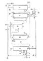
下記に本発明の可能な好適具体化例を示す添付図面を参照して本発明方法の詳細を説明する。この実施例では反応混合物の回収は蒸溜により行っている。勿論図1以外の具体化例も可能である。
【0022】
反応器(I)は十分に断熱された装置、例えば十分に断熱された筒形の反応器であり、加えられたPOXおよびCO2を連続的に良く分配しすべての点において激しく撹拌する内部装置を含んでいる。このような内部装置は当業界に公知であり、例えば孔開きの板、孔開きのトレーおよび調節板、パイプ分配器(挿入型および環状分配器)、二成分ノズル、ジェット・ノズル、ノズル・トレー、ノズル、特にドイツ特許公開明細書第37 36 988号および同第37 44 001号記載のもの、工業的に便利に使用されるガス導入トレー、焼結金属のフリット、PGCを通す孔をもった閉じたガス分配トレー、回転式ガス導入装置、衝突式バッ気装置[ペリース・ケミカル・エンジニアーズ・ハンドブック(Perrys Chemical Engineering Handbook)1984年版18.57〜18.70頁]、混合機素、撹乱を増加させる金属シート内部装置、分割式および環状の調節板がある。これらの内部装置は互いに組合わせて使用することができる。一般にこのような内部装置は流れの混合を良くし(マクロ的な混合)、ガスを細かく分配することの他に、消費区域において出来るだけ大きな割合で高周波の撹乱要素をつくりださなければならない。好適な内部装置は孔開きのトレー、パイプ分配器、二成分ノズル、ジェット・ノズル、特にドイツ特許公開明細書第37 36 988号記載のもの、閉じたガス分配器、衝突式バッ気装置、および混合機素である。
【0023】
本発明の方法において、CO2は図1の具体化例では(1)のところで供給され、POXは(2)のところで供給される。
【0024】
反応器のどこでもPOXはCO2と常に過剰に或いは高濃度の状態でで出会うことが本発明方法において高い選択性を得る上で重要であるから、CO2は流れの方向においてPOXの前に反応器に供給される。このようにCO2をPOXの前に供給することは少なくとも部分的に行われ、残りのCO2は反応器の他の点において1回または数回に分けて供給され、CO2が常にPOXよりも過剰に存在するようにする。図1の好適な具体化例においては、反応器に入って来る前に既に触媒を含み反応器の中に流入して来るPGC(3)の中にCO2を全部または少なくとも部分的に加える。好ましくはこの前以て行うCO2の添加は上記のCO2の範囲の過剰料においてPOXの量よりも1〜50モル%CO2が過剰になるように行われる。POXは後ろの入り口点(4)において好ましくはCO2と混合して加える。このような混合物は特に好適な方法では等モル量のPOXとCO2から成っている。さらに好適な方法では、POX/CO2混合物を少なくとも二つの供給点で反応器に供給する。このような第2の供給点は(5)であり、他の供給点は(6)および(7)その他であることができる。これらの供給されたガスは次に上記の内部装置(分配機素)によって反応媒質の中に均一に分配される。供給点(4)、(5)、(6)、(7)等の数が多いほど、反応器中における局所的な過剰濃度および局所的な温度ピークが避けられる。
【0025】
反応器(I)の中で主反応が減衰した後、利用可能な熱を利用するために反応混合物(8)をフラッシュ蒸発器(II)の加熱ジャケットの中に流し込み、ここから冷却された反応混合物(9)として流して熱交換器(III)によって利用し、この中で水(27)から加熱用の水蒸気(28)を得る。しかし別法として反応器からの流出液(8)を先ず熱交換器(III)の中に通し、次いでフラッシュ蒸発器(II)の加熱用ジャケットに通す。水蒸気を発生させる熱交換器(III)の代わりに、反応が吸熱的に進行する全く異なった過程の反応器を加熱するのに用いることができる。しかし流出液(8)はフラッシュ蒸発器(II)に入る前においても(10)および(11)に対応する部分流に分割することができる。
【0026】
すでに幾分冷却された反応器の流出液(8)および反応混合物(9)に対し、同時に(II)および(III)を通る経路によって後反応が進行する時間が与えられる。
【0027】
図1の実施例においては、利用可能な熱が全体として上記の2〜80℃だけ冷却されて熱交換器(III)を出るさらに冷却された反応混合物は次に部分流(10)および(11)に分割される。部分流(10)は前述のように反応器(I)の全流出流の80〜98重量%を含んでいる。部分流(11)は100%の残りを成している。明らかに原理的には工程の経路の他の点においても(9)を部分流(10)および(11)に分割することができる。
【0028】
部分流(10)は反応器の入口に戻されるが、部分流(11)は回収部へと供給される。この目的のために(11)を先ず膨張容器(IV)に通し、この中で液(12)とガス相(13)への分離を行う。ガス相(13)は過剰のCO2、恐らくは不完全に反応したPOX、およびCO2およびPOXと一緒に導入された不活性ガスを含んでいる。不活性ガスの割合に従って、ガス相(13)は二つの部分流(14)および(15)に分割される。(14)は反応器に戻されるが、(15)は廃ガスの廃棄所(25)に供給される。明らかに、不活性ガスの含量が多いと、多くの割合の(13)が部分流(15)の形で放出される。逆もまた正しい。当業界の専門家は簡単な分析的な決定および計算、並びに予備実験のによって容易にガス相の最適の分割比を決めることができる。
【0029】
(IV)で分離された液(12)は次にフラッシュ蒸発器(II)の内部に通される。フラッシュ蒸発器(II)は好ましくは薄膜蒸発器、落下フィルム式蒸発器、回転管蒸発器、または回転または上昇フィルム蒸発器である。(II)において2〜100ミリバール、好ましくは4〜90ミリバール、、特に好ましくは5〜80ミリバールの真空下において真空蒸溜を行い、蒸発したPGC(16)と塔底流出液(17)を得る。この蒸溜による分離のエネルギーは一方ではフラッシュ蒸発器(II)のジャケットまたは他の加熱装置を通る反応器の流出流(8)から得られ、他方では液相(12)の利用可能な熱から得られる。
【0030】
(II)の塔底流出流(17)は部分流(18)および(19)に分けられる。全量の大部分、例えば60〜98%、好ましくは75〜97%、特に好ましくは90〜96%(17)は部分流(18)として反応器の入り口に戻される。
【0031】
これはなお触媒を含んでいる。さらにこれは反応器の系中を循環する反応媒質としてPGCの循環を閉じている。
【0032】
残りの部分流(19)は触媒の再生装置(VI)へと流される。触媒の再生の種類は使用する個々の触媒に合わせて考えなければならないが、触媒の再生が可能で有る限り、上記の文献から当業界の専門家には公知である。再生装置(IV)から例えば不活性化した触媒の部分(20)を取り出すことができる。再生された触媒はPGC(29)と一緒に部分流(18)と全く同じように反応器の入口に戻される。再生は例えばアルカリ金属ハロゲン化物と2価の金属のハロゲン化物との混合物、例えばNaBr/ZnBr2のような触媒をハロゲン化合物、例えばHBrで処理して行うことができる。
【0033】
消費されて取り出された触媒の補充は新しい触媒を(21)を経て通すことにより行われる。
【0034】
蒸溜されて(II)の内部から出るPGC(16)はさらに熱交換器(V)中で凝縮させて蒸気が回収され、所望の温度に冷却される。このうにして凝縮したPGCは(23)の所で取り出される。
【0035】
蒸発した部分(16)と一緒に(V)へ運ばれたガスの部分(12)は塔頂部から引き出されるガス流としてPGCが凝縮する際に(V)の中につくられ、(22)と(26)とに分割される。(22)は廃ガスの廃棄所(25)へ供給され、(26)は反応器の入口に戻される。部分流(22)および(26)の分割は部分流(14)および(15)に対して述べたのと同じ基準で行われる。
【0036】
(27)は熱交換器(III)および(V)に供給される水であり、これを装置から取り出してその蒸発熱を利用するか、または加熱用水蒸気(28)を生成させる熱を得るのに利用することができる。
【0037】
【実施例】
15バールで作動している図1の反応器Iに(1)を介して毎時全部で0.453kgのCO2を、(2)を介して0.569kgのPOXを計量する。即ちそれぞれ0.108kgのCO2と0.142kgのPOXが混合物としてライン(4)を通って(7)へと流され、0.022kgのCO2(3)は(10)を介して戻される温度約141℃の反応混合物約30.2kgに加えられた後、反応器Iに入るようにする。さらに0.03kgのガス流が膨張室IVから(13)および(14)を介して反応器Iへと流される。
【0038】
反応工程後、温度約159℃の反応混合物31.8kgが反応器を出て流れ(8)としてフラッシュ蒸発器IIのジャケットへと流され、その中で蒸溜を行うために加熱された後約150℃においてジャケットを出、流れ(9)として熱交換器IIIに流れ込み、水蒸気を発生させた後約140℃で熱交換器を出て行き、次いで約30.2kgの流れ(10)と約1.6kgの流れ(11)に分割される。(10)は前述のように反応器へ戻され、(11)はIVの中で1バールに減圧され、0.03kgのガス相(13)はIへ通され、1.57kgの液相はフラッシュ蒸発器IIへ通され、ここで約50ミリバールにおいて約1.03kgの蒸気のPGC(16)と約0.54kgの塔底生成物(17)に分割される。この場合逃げ出して行く残りの約0.03kgのガスは(22)および(25)を介して廃ガス廃棄所へと取り出される。PGC(16)は熱交換器Vの中で凝縮し、水蒸気を発生させる。
【0039】
塔底生成物(17)を約9:1に分割した後、多い方の約0.49kgは流れ(18)および(21)としてIへと流され、少ない方の約0.05kg(19)は再生装置VIへと流され、極めて僅かのハロゲン化合物で処理した後、再び(29)として再生装置から出て(21)として反応器に戻される。
【0040】
本発明の主な特徴及び態様は次の通りである。
1.プロピレングリコールオキシド(POX)および二酸化炭素をプロピレングリコールカーボネート(PGC)を反応媒質として高温、高圧において反応させ、生成したPGCを触媒と分離することによりプロピレングリコールカーボネートを触媒を用いて製造する方法において、
(a)該工程を圧力2〜200バール、好ましくは5〜80バール、特に好ましくは8〜60バール、温度範囲110〜200℃、好ましくは110〜190℃、特に好ましくは110〜180℃において、断熱的な温度上昇を2〜80℃とし、断熱的な温度上昇が上記範囲内に保持されるように入り口温度を選んで工程を連続的且つ断熱的に行い、
(b)反応媒質として単位時間当たりに流すPGCをこの単位時間において生成されるPGCの量の7〜350倍にし、
(c)1モルのPOX当たり1.01〜1.5モル、好ましくは1.01〜1.4モル、特に好ましくは1.01〜1.35モルの二酸化炭素を使用し、反応器のすべての点において二酸化炭素を過剰に保ち、
(d)全反応混合物の80〜98重量%、好ましくは85〜97重量%を反応器の入口へ戻し、残りを回収してPGCを製造する方法。
【0041】
2.反応器の中で激しく撹拌を行う上記第1項記載の方法。
【0042】
3.反応器は孔開きのトレー、パイプ分配器、二成分ノズル、ジェット・ノズル、ノズル、閉じたガス分配器、衝突式バッ気機素、混合機素またはこれらの幾つかの組合わせを含んでいる上記第2項記載の方法。
【0043】
4.二酸化炭素を過剰に保つために、二酸化炭素の少なくとも一部を反応媒質として作用するPGCの中に供給した後POXを注入し、この二酸化炭素を好ましくは反応器に入る前にPGCに加える上記第1項記載の方法。
【0044】
5.POXを単独または残った二酸化炭素との混合物とし、常に二酸化炭素が過剰に存在するように、その後方にある少なくとも二つの点において反応器に供給する上記第4項記載の方法。
【0045】
6.過剰の二酸化炭素は反応器に入る前にPGCに加えられ、残りの二酸化炭素はPOX/CO2等モル混合物として反応器に供給される上記第5項記載の方法。
【0046】
7.反応混合物で得られる利用可能な熱は反応混合物を回収してPGCを得るかおよび/または加熱用の水蒸気を発生させるか、および/または吸熱反応を進行させるのに利用することができる上記第1項記載の方法。
【0047】
8.利用可能な熱を回収する際、反応混合物が2〜80℃冷却される上記第1項記載の方法。
【0048】
9.回収してPGCを得る工程は回収した利用可能な熱を利用して行われる上記第1項記載の方法。
【0049】
10.該回収は圧力2〜100ミルバール、好ましくは4〜90ミルバール、特に好ましくは5〜80ミルバールで蒸溜することにより行われる上記第9項記載の方法。
【図面の簡単な説明】
【図1】本発明方法の可能な具体化例を示している。[0001]
The present invention is a process for continuously producing propylene oxide (POX) and carbon dioxide (CO2) to propylene glycol carbonate (PGC) using a catalyst, characterized in that it saves energy and materials in an adiabatic manner, and especially in a mild manner. About.
[0002]
Many proposals have been made for a method for producing PGCs. These proposals are mainly concerned with the use of certain catalysts. A method for producing PGC or ethylene glycol carbonate (EGC) from POX or ethylene oxide (EOX) and CO 2 respectively is described in Chem. Ing. techn. 43 (1971), p. 903. This method is also described in Fette, Seifen, Anstrichmittel, Vol. 73 (1971), p. 396, in which only the method of producing EGC is discussed in detail. When producing EGC, the adiabatic temperature conditions as discussed herein are not industrially realized (see p. 398 of the same publication). In the process as described herein, CO2 and EOX are reacted together with ethylene glycol carbonate in a reactor at a temperature of at least 80 bar and a temperature of 190-200 ° C., and a countercurrent circulating transfer The heat of reaction is removed by a heating medium, wherein the heat transfer medium is cooled with water. Under such reaction conditions, a peak temperature of up to 220 ° C. is obtained in the reactor, but such temperature acts to degrade the product. This is clearly described in the literature (p. 397). This problem is difficult to overcome, especially in industrial scale factories. In this case, all energy of the reaction is removed without being used. The reaction of POX reacting with CO 2 to give PGC is a highly exothermic reaction similar to the reaction of EOX reacting with CO 2 to give EGC, and the temperature at the peak also acts to degrade PGC. , above Fette, Seifen, what is described in Anstrichmittel magazine also applies to the case of manufacturing the PGC from POX and CO 2. The method described in the aforementioned Fette, Seifen, Anstrichmittel and the above described Chem. Ing. Techn. In contrast to the method described in the journal, adiabatic temperature conditions are characterized in that all the heat of reaction released is absorbed by the reaction mixture itself. In the case of an exothermic reaction, this raises the temperature of the reaction mixture.
[0003]
In U.S. Patent No. 4 314 945 described the process, the reaction for producing alkylene carbonate from alkylene oxide and CO 2 Metropolitan causes essentially combining the flow pipe and pressurized circulation reactor variously, it It is carried out by operating at 10 to 50 bar up to 200 ° C. The corresponding carbonate serves as the reaction medium in all reactor parts, in each case 85 to 99.6% by weight of the reactor contents.
[0004]
The alkylene oxide is metered and introduced together with the catalyst dissolved in the carbonate into the first reaction zone of such a combination device.
[0005]
In the preferred method of US 4 314 945, supplies poorly in in the pressurized circulating reactor combination device having a flow pipe, the CO 2 in the other distant points of the reactor. In the first reactor of such a combination device, the local concentration of alkylene oxide is still high in the immediate vicinity of the metering zone, and the metering of the type chosen here has an adverse effect on the selectivity. That is, the alkylene oxide is promoted by a high local catalyst concentration and a low CO 2 concentration, rearranges to acetaldehyde, and acts as a base for the polycondensation reaction.
[0006]
A further disadvantage is that the CO 2 is supplied only slightly over the catalyst (not over the alkylene oxide).
[0007]
The element of such a combination device used in U.S. Pat. No. 4,314,945, i.e., the reactor, on the one hand has an external circulator and heat exchanger for cooling the product, and is provided with an agitator. Or a pressurized circulation reactor consisting of a stirred tank stirred by the inflow of gas or liquid, on the other hand equipped with a cooler at the rear or operated under adiabatic conditions with its own cooler It is a flow pipe.
[0008]
Pressurized circulation reactors are characterized in that high pressure circulation rates are used in the case of exothermic reactions, and the heat of reaction is removed during the reaction in the reactor and the associated heat exchanger. This method is completely different from the adiabatic method in which the reaction is completed in one pass through the reactor and the total heat of reaction is absorbed by the reaction medium.
[0009]
What is common to the elements of the reactor described in U.S. Pat. No. 4,314,945 is that the change in alkylene oxide within each of the elements is independent of the number and order of elements within the combination. Is only partially happening. This is because the problem of heat in the highly exothermic reaction between alkylene oxide and CO 2 has not been solved.
[0010]
Only by complex connections of the individual elements, each equipped with a cooler, at least in all partial changes, a conversion of alkylene oxide of at least about 99.5% and a selectivity of carbonate of at least about 99% are achieved. Have been.
[0011]
Utilizing the heat of reaction available in the process itself and to produce steam is not described in U.S. Pat. No. 4,314,945.
[0012]
At present, there is a demand for a method that avoids a peak temperature that degrades the product on the one hand, and that utilizes heat of reaction as much as possible on the other hand. In the present invention, such utilization of the heat of reaction is carried out, for example, by recovering a crude product or generating steam for heating for another step.
[0013]
In the present invention, propylene glycol oxide (POX) and carbon dioxide are reacted at a high temperature and a high pressure using propylene glycol carbonate (PGC) as a reaction medium, and the produced PGC is separated from the catalyst, whereby propylene glycol carbonate is used as a catalyst. In the method of manufacturing,
(A) the process is carried out at a pressure of from 2 to 200 bar, preferably from 5 to 80 bar, particularly preferably from 8 to 60 bar, in a temperature range from 110 to 200 ° C, preferably from 110 to 190 ° C, particularly preferably from 110 to 180 ° C; The adiabatic temperature rise is 2 to 80 ° C., and the process is performed continuously and adiabatically by selecting the inlet temperature so that the adiabatic temperature rise is maintained within the above range,
(B) The PGC flowing per unit time as a reaction medium is made 7 to 350 times the amount of PGC generated in this unit time,
(C) using 1.01 to 1.5 mol, preferably 1.01 to 1.4 mol, particularly preferably 1.01 to 1.35 mol of carbon dioxide per mol of POX, Keep carbon dioxide in excess in terms of
(D) A process has been found characterized in that 80-98% by weight, preferably 85-97% by weight, of the total reaction mixture is returned to the inlet of the reactor and the remainder is recovered to produce PGCs.
[0014]
The feeds POX and CO 2 are generally of at least 99% purity. However the remainder of inert material reaches 100%, such as hydrocarbons, in the case of carbon monoxide or nitrogen, may be used low purity POX and CO 2. This can be particularly applicable to CO 2, CO 2 those from a variety of sources, such as those of naturally occurring or water gas, obtained from the factory to generate carbon monoxide, or reformed gas, thus the purity Can be low. However, such an inert gas is conveniently at most 10%, preferably at most 5%, particularly preferably at most 3%, by volume.
[0015]
The catalysts used are virtually all catalysts proposed hitherto, such as alkali metal bromides and alkaline earth metal bromides, and alkali metal iodides and alkaline earth metal iodides, guanidine and its bromides. Hydrochloride and hydroiodide, tetraalkylammonium bromide and tetraalkylammonium iodide, phosphonium bromide and phosphonium iodide, pyridinium halide, sulfonium halide, stibonium halide and arsonium halide, Zinc and lead halides, alkyltin compounds, and mixtures of alkali halides with halides of divalent metal ions (French Patent 1 538 576, Belgian Patent 872 960, European Patent 297 647) U.S. Pat. Nos. 3,535,342, 2,773,070, 2,994,705, German Patent 1,543,555, U.S. Pat. No. 3,535,41, Belgian Patents 798,171, 872,959, and German Patent Publication. No. 32,444,456, British Patent No. 2,098,985, European Patent Nos. 133,763 and 180,387, J. Org.Chem., Vol. 45 (1980), p. 3735, Chem. Lett., 1979, p. 573. , German Patent Publication No. 41 05 554). Preferably used catalysts are alkali metal bromides and alkali metal iodides, tetraalkylammonium bromide and tetraalkylammonium iodide, phosphonium halides, guanidinium halides, and alkali metal halides and divalent It is a mixture with a metal halide.
[0016]
The process according to the invention is carried out in a temperature range from 110 to 200 ° C., preferably from 110 to 190 ° C., particularly preferably from 110 to 180 ° C. The pressure of the process according to the invention is between 2 and 200 bar, preferably between 5 and 80 bar, particularly preferably between 8 and 60 bar. Temperatures in the upper part of the range use the pressure in the upper part of the range, and vice versa.
[0017]
The method of the invention is carried out under adiabatic temperature conditions, wherein the adiabatic temperature rise is 2 to 80C. In this case, the inlet temperature is chosen such that, even when the temperature raised by the selected adiabaticity is fully utilized, the upper limit of the temperature given over the entire process is not exceeded.
[0018]
According to the invention, the CO 2 is kept in excess at all points of the reactor with respect to the other reactant POX. 1.01-1.5 mole per POX1 moles for this purpose, preferably 1.01 to 1.4 mol, particularly preferably used from 1.01 to 1.35 moles of CO 2.
[0019]
PGC is always present in a large excess as a reaction medium over newly generated PGC. Therefore, 7 to 350 times the PGC generated per unit time in this unit time is passed through the reactor as a circulating PGC containing a catalyst. Such a large excess is such that 80-98% by weight, preferably 85-97% by weight, of the total reaction mixture is returned to the reactor inlet, and only the remainder up to 100% is withdrawn and recovered, It is maintained so as to be a good PGC.
[0020]
It is another feature of the process of the invention to use the available heat of the reaction mixture obtained from adiabatic temperature conditions. The most important of these possible uses in this case is the use in recovering the reaction mixture to pure PGCs. However, the available heat temperature of the resulting reaction product is generally very high and can generate steam for heating which can be supplied to other (endothermic) steps. In this case, it is preferable to cool the reaction mixture to about 2 to 80 ° C. in order to recover available heat.
Vigorous mixing is performed in the reactor to avoid undesired temperature peaks.
[0021]
The details of the method of the present invention will be described below with reference to the accompanying drawings showing possible preferred embodiments of the present invention. In this example, the reaction mixture is recovered by distillation. Of course, specific examples other than FIG. 1 are also possible.
[0022]
Reactor (I) is a well-insulated device, for example a well-insulated tubular reactor, an internal device that distributes the added POX and CO 2 continuously and vigorously at all points. Contains. Such internal devices are known in the art and include, for example, perforated plates, perforated trays and adjustment plates, pipe distributors (insertion and annular distributors), two-component nozzles, jet nozzles, nozzle trays. , Nozzles, in particular those described in DE-OS 37 36 988 and DE 37 44 001, with gas introduction trays, sintered metal frits and holes for the passage of PGCs, which are industrially conveniently used. Closed gas distribution tray, rotary gas introduction device, impingement baffle device (Perrys Chemical Engineering Handbook, 1984 edition 18.57-18.70), mixing element, disturbance There are augmented metal sheet internal devices, split and annular adjustment plates. These internal devices can be used in combination with each other. In general, such internal devices must, besides providing good mixing of the streams (macroscopic mixing) and fine distribution of the gas, produce as high a frequency disturbance as possible in the consumption area. Suitable internal devices are perforated trays, pipe distributors, two-component nozzles, jet nozzles, especially those described in DE-A 37 36 988, closed gas distributors, impingement air blowers, and It is a mixing element.
[0023]
In the method of the present invention, CO 2 is provided at (1) and POX is provided at (2) in the embodiment of FIG.
[0024]
Because everywhere POX reactors can meet at always excess or high concentration state as CO 2 is important for obtaining a high selectivity in the method of the present invention, CO 2 reaction before the POX in the direction of flow Supplied to the vessel. Feeding the CO 2 before the POX in this way is at least partially done, the remaining CO 2 being fed once or several times at other points in the reactor, the CO 2 always being supplied from the POX. Also be present in excess. In a preferred embodiment example of FIG. 1, all CO 2 into the come already before entering the reactor flows into the reactor containing the catalyst PGC (3) or at least partially added. Preferably carried out as 1-50 mole% CO 2 than the amount of POX is excessive in excess charges ranging addition of CO 2 to perform this beforehand is above the CO 2. POX is added at the rear entry point (4), preferably mixed with CO2. Such mixture is composed of equimolar amounts of POX and CO 2 in a particularly preferred method. In a further preferred method, the POX / CO 2 mixture is fed to the reactor at at least two feed points. Such a second supply point is (5) and other supply points can be (6) and (7) and others. These supplied gases are then evenly distributed in the reaction medium by the internal device (distribution element) described above. The greater the number of feed points (4), (5), (6), (7), etc., the more local overconcentration and local temperature peaks in the reactor are avoided.
[0025]
After the main reaction has decayed in the reactor (I), the reaction mixture (8) is poured into the heating jacket of the flash evaporator (II) to make use of the available heat, from which the cooled reaction It flows as a mixture (9) and is utilized by means of a heat exchanger (III) in which water (27) is obtained from water (27) for heating. Alternatively, however, the effluent (8) from the reactor is first passed through the heat exchanger (III) and then through the heating jacket of the flash evaporator (II). Instead of a heat exchanger (III) for generating steam, it can be used to heat a completely different reactor in which the reaction proceeds endothermically. However, even before entering the flash evaporator (II), the effluent (8) can be split into partial streams corresponding to (10) and (11).
[0026]
The reactor effluent (8) and the reaction mixture (9), which have already been cooled somewhat, are given the time for the post-reaction to proceed by a route through (II) and (III) simultaneously.
[0027]
In the embodiment of FIG. 1, the available heat is cooled by a total of 2 to 80 ° C. as described above and the further cooled reaction mixture leaving the heat exchanger (III) is then passed to the partial streams (10) and (11). ). The partial stream (10) comprises 80 to 98% by weight of the total effluent of the reactor (I) as described above. The partial stream (11) makes up the remainder of 100%. Obviously, in principle, (9) can also be split into partial streams (10) and (11) at other points in the process path.
[0028]
The partial stream (10) is returned to the reactor inlet, while the partial stream (11) is fed to a recovery. For this purpose, (11) is first passed through an expansion vessel (IV), in which separation into a liquid (12) and a gas phase (13) takes place. The gas phase (13) contains excess CO 2 , possibly incompletely reacted POX, and an inert gas introduced together with CO 2 and POX. According to the proportion of inert gas, the gas phase (13) is divided into two partial streams (14) and (15). (14) is returned to the reactor, while (15) is fed to a waste gas dump (25). Obviously, a high content of inert gas releases a large proportion of (13) in the form of a partial stream (15). The converse is also true. Experts in the art can easily determine the optimal splitting ratio of the gas phase by simple analytical determinations and calculations and preliminary experiments.
[0029]
The liquid (12) separated in (IV) is then passed through a flash evaporator (II). The flash evaporator (II) is preferably a thin film evaporator, a falling film evaporator, a rotating tube evaporator, or a rotating or rising film evaporator. In (II), vacuum distillation is carried out under a vacuum of 2 to 100 mbar, preferably 4 to 90 mbar, particularly preferably 5 to 80 mbar, to obtain an evaporated PGC (16) and a bottom effluent (17). The energy of this distillation separation is obtained on the one hand from the reactor effluent (8) through the jacket of a flash evaporator (II) or other heating device, and on the other hand from the available heat of the liquid phase (12). Can be
[0030]
The bottoms effluent (17) of (II) is divided into partial streams (18) and (19). Most of the total amount, for example 60-98%, preferably 75-97%, particularly preferably 90-96% (17) is returned to the reactor inlet as a partial stream (18).
[0031]
It still contains the catalyst. It also closes off the circulation of PGCs as the reaction medium circulating in the reactor system.
[0032]
The remaining partial stream (19) is passed to a catalyst regenerator (VI). The type of regeneration of the catalyst must be considered for the particular catalyst used, but is known to the expert in the art from the above-mentioned literature, as long as the regeneration of the catalyst is possible. For example, a portion (20) of the deactivated catalyst can be removed from the regenerator (IV). The regenerated catalyst is returned to the reactor inlet together with the PGC (29), just like the partial stream (18). Regeneration can be performed, for example, by treating a mixture of an alkali metal halide and a divalent metal halide, for example, a catalyst such as NaBr / ZnBr 2 with a halogen compound, for example, HBr.
[0033]
Replenishment of spent and removed catalyst is effected by passing fresh catalyst through (21).
[0034]
The PGC (16) distilled from the inside of (II) is further condensed in a heat exchanger (V) to recover steam and cooled to a desired temperature. The PGC condensed in this way is taken out at (23).
[0035]
A portion (12) of the gas conveyed to (V) together with the evaporated portion (16) is formed in (V) as the PGC condenses as a gas stream withdrawn from the top, and (22) (26). (22) is fed to a waste gas dump (25) and (26) is returned to the reactor inlet. The division of the partial streams (22) and (26) is performed on the same basis as described for the partial streams (14) and (15).
[0036]
(27) is water supplied to the heat exchangers (III) and (V), which is taken out of the apparatus and uses the heat of evaporation or obtains heat for generating steam for heating (28). Can be used for
[0037]
【Example】
A total of 0.453 kg of CO 2 / hour via (1) and 0.569 kg of POX via (2) are metered into the reactor I of FIG. 1 operating at 15 bar. That is, 0.108 kg of CO 2 and 0.142 kg of POX, respectively, are flowed as a mixture through line (4) to (7), and 0.022 kg of CO 2 (3) is returned via (10) After being added to about 30.2 kg of the reaction mixture at a temperature of about 141 ° C., it is allowed to enter reactor I. A further 0.03 kg gas flow is passed from the expansion chamber IV to the reactor I via (13) and (14).
[0038]
After the reaction step, 31.8 kg of the reaction mixture at a temperature of about 159 ° C. exit the reactor as stream (8) and flow to the jacket of the flash evaporator II, where it is heated to carry out the distillation and then about 150 kg. C., exits the jacket at a temperature of about 140 ° C. and exits the heat exchanger at about 140 ° C. after generating steam, and then about 30.2 kg of stream (10) and about 1. It is divided into a 6 kg stream (11). (10) is returned to the reactor as described above, (11) is depressurized to 1 bar in IV, 0.03 kg gas phase (13) is passed to I, and 1.57 kg liquid phase is It is passed to flash evaporator II where it is split at about 50 mbar into about 1.03 kg of vapor PGC (16) and about 0.54 kg of bottom product (17). In this case, the remaining about 0.03 kg of escaping gas is withdrawn via (22) and (25) to the waste gas dump. The PGC (16) condenses in the heat exchanger V to generate steam.
[0039]
After splitting the bottoms product (17) about 9: 1, about 0.49 kg of the larger is passed to I as streams (18) and (21) and about 0.05 kg (19) of the smaller Is flowed to the regenerator VI, treated with very little halogen compound and then leaves the regenerator again as (29) and is returned to the reactor as (21).
[0040]
The main features and aspects of the present invention are as follows.
1. A method for producing propylene glycol carbonate using a catalyst by reacting propylene glycol oxide (POX) and carbon dioxide at high temperature and high pressure using propylene glycol carbonate (PGC) as a reaction medium and separating the produced PGC from the catalyst.
(A) the process is carried out at a pressure of from 2 to 200 bar, preferably from 5 to 80 bar, particularly preferably from 8 to 60 bar, in a temperature range from 110 to 200 ° C, preferably from 110 to 190 ° C, particularly preferably from 110 to 180 ° C; The adiabatic temperature rise is 2 to 80 ° C., and the process is performed continuously and adiabatically by selecting the inlet temperature so that the adiabatic temperature rise is maintained within the above range,
(B) The PGC flowing per unit time as a reaction medium is made 7 to 350 times the amount of PGC generated in this unit time,
(C) using 1.01 to 1.5 mol, preferably 1.01 to 1.4 mol, particularly preferably 1.01 to 1.35 mol of carbon dioxide per mol of POX, Keep carbon dioxide in excess in terms of
(D) A method for producing PGC by returning 80 to 98% by weight, preferably 85 to 97% by weight of the total reaction mixture to the inlet of the reactor and recovering the remainder.
[0041]
2. The method according to claim 1, wherein vigorous stirring is performed in the reactor.
[0042]
3. Reactors include perforated trays, pipe distributors, two-component nozzles, jet nozzles, nozzles, closed gas distributors, impingement bubbling elements, mixing elements, or some combination thereof. 3. The method of
[0043]
4. In order to keep carbon dioxide in excess, POX is injected after feeding at least a portion of the carbon dioxide into the PGC acting as a reaction medium, and the carbon dioxide is preferably added to the PGC before entering the reactor. The method of claim 1.
[0044]
5. 5. A process according to claim 4, wherein POX is used alone or in a mixture with the remaining carbon dioxide and is fed to the reactor at at least two points behind it so that carbon dioxide is always present in excess.
[0045]
6. Excess carbon dioxide is added to the PGC before entering the reactor, the method of the fifth Claims remaining carbon dioxide supplied to the reactor as a POX / CO 2 equimolar mixture.
[0046]
7. The available heat obtained in the reaction mixture can be used to recover the reaction mixture to obtain PGCs and / or to generate steam for heating and / or to advance the endothermic reaction. The method described in the section.
[0047]
8. The method of claim 1 wherein the reaction mixture is cooled at 2-80 ° C. upon recovering available heat.
[0048]
9. 2. The method according to claim 1, wherein the step of recovering to obtain PGC is performed using recovered available heat.
[0049]
10. 10. The process according to
[Brief description of the drawings]
FIG. 1 shows a possible embodiment of the method according to the invention.
Claims (1)
(a)該工程を圧力2〜200バール、温度範囲110〜200℃において、断熱的な温度上昇を2〜80℃とし、断熱的な温度上昇が上記範囲内に保持されるように入り口温度を選んで工程を連続的且つ断熱的に行い、
(b)反応媒質として単位時間当たりに流すPGCをこの単位時間において生成されるPGCの量の7〜350倍にし、
(c)1モルのPOX当たり1 . 01〜1 . 5モルの二酸化炭素を使用し、反応器のすべての点において二酸化炭素を過剰に保ち、
(d)全反応混合物の80〜98重量%を反応器の入口へ戻し、残りを回収してPGCを製造することを特徴とする方法。A method for producing propylene glycol carbonate using a catalyst by reacting propylene glycol oxide (POX) and carbon dioxide at high temperature and high pressure using propylene glycol carbonate (PGC) as a reaction medium and separating the produced PGC from the catalyst.
(A) at a pressure of 2 to 200 bar and a temperature range of 110 to 200 ° C, an adiabatic temperature rise of 2 to 80 ° C, and an inlet temperature of such that the adiabatic temperature rise is maintained within the above range. Choose and perform the process continuously and adiabatically,
(B) The PGC flowing per unit time as a reaction medium is made 7 to 350 times the amount of PGC generated in this unit time,
(C) 1 per mole of POX. 01 to 1. Use the 5 moles of carbon dioxide, excess keeping carbon dioxide at all points of the reactor,
(D) A method characterized in that 80 to 98% by weight of the total reaction mixture is returned to the inlet of the reactor, and the remainder is recovered to produce PGC.
Applications Claiming Priority (2)
| Application Number | Priority Date | Filing Date | Title |
|---|---|---|---|
| DE4318892.3 | 1993-06-07 | ||
| DE4318892A DE4318892A1 (en) | 1993-06-07 | 1993-06-07 | Process for the production of propylene glycol carbonate |
Publications (2)
| Publication Number | Publication Date |
|---|---|
| JPH06345698A JPH06345698A (en) | 1994-12-20 |
| JP3583473B2 true JP3583473B2 (en) | 2004-11-04 |
Family
ID=6489814
Family Applications (1)
| Application Number | Title | Priority Date | Filing Date |
|---|---|---|---|
| JP14073594A Expired - Fee Related JP3583473B2 (en) | 1993-06-07 | 1994-06-01 | Method for producing propylene glycol carbonate |
Country Status (6)
| Country | Link |
|---|---|
| US (1) | US5449791A (en) |
| EP (1) | EP0628554B1 (en) |
| JP (1) | JP3583473B2 (en) |
| CA (1) | CA2125075C (en) |
| DE (2) | DE4318892A1 (en) |
| ES (1) | ES2149227T3 (en) |
Families Citing this family (8)
| Publication number | Priority date | Publication date | Assignee | Title |
|---|---|---|---|---|
| ATE483704T1 (en) * | 2003-06-04 | 2010-10-15 | Asahi Kasei Chemicals Corp | METHOD FOR PRODUCING ALKYLENE CARBONATE |
| TWI378087B (en) * | 2006-02-22 | 2012-12-01 | Shell Int Research | Process for the preparation of an alkanediol and a dialkyl carbonate |
| TWI383976B (en) * | 2006-02-22 | 2013-02-01 | Shell Int Research | Process for the production of dialkyl carbonate and alkanediol |
| TW200740749A (en) * | 2006-02-22 | 2007-11-01 | Shell Int Research | Process for the preparation of an alkanediol and a dialkyl carbonate |
| TW200740731A (en) * | 2006-02-22 | 2007-11-01 | Shell Int Research | Process for the preparation of alkanediol |
| TWI382979B (en) * | 2006-02-22 | 2013-01-21 | Shell Int Research | Process for the production of alkylene carbonate and use of alkylene carbonate thus produced in the manufacture of an alkane diol and a dialkyl carbonate |
| TWI387584B (en) * | 2006-03-13 | 2013-03-01 | Shell Int Research | Process for the production of alkylene carbonate and use of alkylene carbonate thus produced in the manufacture of an alkane diol and a dialkyl carbonate |
| CN101663288B (en) * | 2007-04-23 | 2013-08-21 | 国际壳牌研究有限公司 | Process for preparing an 1,2-alkylene carbonate |
Family Cites Families (9)
| Publication number | Priority date | Publication date | Assignee | Title |
|---|---|---|---|---|
| SU172342A (en) * | ||||
| US4314945A (en) * | 1977-12-22 | 1982-02-09 | Union Carbide Corporation | Alkylene carbonate process |
| US4247465A (en) * | 1979-08-23 | 1981-01-27 | Atlantic Richfield Company | Preparation of alkylene carbonates from olefins |
| JPS6059218B2 (en) * | 1980-12-23 | 1985-12-24 | 株式会社日本触媒 | Method for producing alkylene glycol |
| DE3736988C1 (en) * | 1987-10-31 | 1989-03-23 | Bayer Ag | Process for the continuous production of organic mono- and polyisocyanates |
| DE4028708A1 (en) * | 1990-09-10 | 1992-03-12 | Huels Chemische Werke Ag | METHOD FOR THE PRODUCTION OF HIGH-PURITY PROPYLENE CARBONATE AND THE SIMULTANEOUS PRODUCTION OF PASSIVATED ELECTRODES |
| DE4129753C2 (en) * | 1991-09-04 | 1995-05-04 | Dainippon Ink & Chemicals | Process for the preparation of cyclocarbonate compounds |
| DE4141189A1 (en) * | 1991-12-13 | 1993-06-17 | Bayer Ag | METHOD FOR PRODUCING ETHYLENE GLYCOL CARBONATE |
| US5281723A (en) * | 1992-08-04 | 1994-01-25 | International Business Machines | Propylene carbonate recovery process |
-
1993
- 1993-06-07 DE DE4318892A patent/DE4318892A1/en not_active Withdrawn
-
1994
- 1994-05-25 EP EP94108038A patent/EP0628554B1/en not_active Expired - Lifetime
- 1994-05-25 ES ES94108038T patent/ES2149227T3/en not_active Expired - Lifetime
- 1994-05-25 DE DE59409466T patent/DE59409466D1/en not_active Expired - Lifetime
- 1994-05-31 US US08/251,456 patent/US5449791A/en not_active Expired - Lifetime
- 1994-06-01 JP JP14073594A patent/JP3583473B2/en not_active Expired - Fee Related
- 1994-06-03 CA CA002125075A patent/CA2125075C/en not_active Expired - Fee Related
Also Published As
| Publication number | Publication date |
|---|---|
| CA2125075A1 (en) | 1994-12-08 |
| EP0628554B1 (en) | 2000-08-02 |
| CA2125075C (en) | 2005-08-16 |
| EP0628554A1 (en) | 1994-12-14 |
| ES2149227T3 (en) | 2000-11-01 |
| US5449791A (en) | 1995-09-12 |
| JPH06345698A (en) | 1994-12-20 |
| DE59409466D1 (en) | 2000-09-07 |
| DE4318892A1 (en) | 1994-12-08 |
Similar Documents
| Publication | Publication Date | Title |
|---|---|---|
| US5508442A (en) | Reactor and continuous process to be carried out therewith for the preparation of ethylene glycol carbonate and propylene glycol carbonate | |
| KR100609674B1 (en) | Continuous production method of 1,3-dioxolane-2-one | |
| KR100337577B1 (en) | Manufacturing Method of Dimethyl Carbonate | |
| CA2191394C (en) | Ethylene glycol process | |
| JP2778878B2 (en) | Method for producing ethylene oxide | |
| KR100379816B1 (en) | Process for continuous production of dialkyl carbonate and diol | |
| JP2926523B2 (en) | Dimethyl carbonate production method | |
| JP2931753B2 (en) | Method for producing C1-C4-alkyl nitrite | |
| JP3419007B2 (en) | Method for producing ethylene glycol carbonate | |
| JPS5852970B2 (en) | Continuous production method of alkylene glycol from alkylene carbonate | |
| JPH06345698A (en) | Production of propylene glycol carbonate | |
| ES2213865T3 (en) | PROCEDURE FOR THE PRODUCTION OF A RENTAL NITRITE. | |
| JPS6059218B2 (en) | Method for producing alkylene glycol | |
| JP4380102B2 (en) | Method for producing dimethyl carbonate | |
| EP3770139A1 (en) | Improved processes for preparing halogenated alkanes | |
| SU602115A3 (en) | Method of obtaining urea | |
| JP2008534645A (en) | Method for continuously producing methyl mercaptan | |
| US3290308A (en) | Synthesis of pure melamine | |
| JP3810144B2 (en) | Continuous production method of diaryl carbonate | |
| JPH1017529A (en) | Continuous production of aryl carbonate | |
| KR20030031569A (en) | Method for the production of melamine | |
| US4691060A (en) | Process for recovering waste heat from formaldehyde product gas | |
| RU2172311C2 (en) | Method of continuous preparation of methyl mercaptan | |
| JP3807124B2 (en) | Nitrite ester production method | |
| US4110374A (en) | Process for separating and recovering unreacted materials in urea synthesis |
Legal Events
| Date | Code | Title | Description |
|---|---|---|---|
| A131 | Notification of reasons for refusal |
Free format text: JAPANESE INTERMEDIATE CODE: A131 Effective date: 20031224 |
|
| A601 | Written request for extension of time |
Free format text: JAPANESE INTERMEDIATE CODE: A601 Effective date: 20040323 |
|
| A602 | Written permission of extension of time |
Free format text: JAPANESE INTERMEDIATE CODE: A602 Effective date: 20040402 |
|
| A521 | Written amendment |
Free format text: JAPANESE INTERMEDIATE CODE: A523 Effective date: 20040623 |
|
| TRDD | Decision of grant or rejection written | ||
| A01 | Written decision to grant a patent or to grant a registration (utility model) |
Free format text: JAPANESE INTERMEDIATE CODE: A01 Effective date: 20040720 |
|
| A61 | First payment of annual fees (during grant procedure) |
Free format text: JAPANESE INTERMEDIATE CODE: A61 Effective date: 20040729 |
|
| R150 | Certificate of patent or registration of utility model |
Free format text: JAPANESE INTERMEDIATE CODE: R150 |
|
| FPAY | Renewal fee payment (event date is renewal date of database) |
Free format text: PAYMENT UNTIL: 20080806 Year of fee payment: 4 |
|
| FPAY | Renewal fee payment (event date is renewal date of database) |
Free format text: PAYMENT UNTIL: 20080806 Year of fee payment: 4 |
|
| FPAY | Renewal fee payment (event date is renewal date of database) |
Free format text: PAYMENT UNTIL: 20090806 Year of fee payment: 5 |
|
| FPAY | Renewal fee payment (event date is renewal date of database) |
Free format text: PAYMENT UNTIL: 20090806 Year of fee payment: 5 |
|
| FPAY | Renewal fee payment (event date is renewal date of database) |
Free format text: PAYMENT UNTIL: 20100806 Year of fee payment: 6 |
|
| FPAY | Renewal fee payment (event date is renewal date of database) |
Free format text: PAYMENT UNTIL: 20110806 Year of fee payment: 7 |
|
| LAPS | Cancellation because of no payment of annual fees |