JP3588024B2 - Rail change lock release device for rail-to-rail variable bogies for railway vehicles - Google Patents
Rail change lock release device for rail-to-rail variable bogies for railway vehicles Download PDFInfo
- Publication number
- JP3588024B2 JP3588024B2 JP34386999A JP34386999A JP3588024B2 JP 3588024 B2 JP3588024 B2 JP 3588024B2 JP 34386999 A JP34386999 A JP 34386999A JP 34386999 A JP34386999 A JP 34386999A JP 3588024 B2 JP3588024 B2 JP 3588024B2
- Authority
- JP
- Japan
- Prior art keywords
- rail
- gauge
- axle
- lock release
- engaging
- Prior art date
- Legal status (The legal status is an assumption and is not a legal conclusion. Google has not performed a legal analysis and makes no representation as to the accuracy of the status listed.)
- Expired - Fee Related
Links
Images


Landscapes
- Handcart (AREA)
Description
【0001】
【発明の属する技術分野】
本発明は、例えば新幹線と在来線のように軌間寸法が異なるレール上を連続して走行するために車輪間隔を変化させることができる鉄道車両用軌間可変台車に関し、より詳しくは車輪を軌間変更不能に固定するロックを確実に解除して軌間変更をスムーズに行えるようにする軌間変更ロック解除装置に関する。
【0002】
日本の鉄道においては、例えば新幹線等に使用されている軌間寸法1435mmの標準軌と、在来線等に使用されている軌間寸法1067mmの狭軌とが併用用されているが、これらの軌間の異なる軌道上を連続して走行し得る鉄道車両を開発すれば、乗客の利便性や、到達時間の短縮、鉄道建設費の低減等、そのメリットは極めて大きい。そこで、本願の出願人は種々の鉄道車両用軌間可変台車を開発し先に出願している。(特開平8−332950号公報他参照)
【0003】
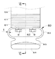
このような鉄道車両用軌間可変台車の構造の概略を図8を参照して説明すると、軸箱1に対して上下方向に昇降可能に支持された車軸2には、車軸外筒3が車軸2の軸線方向にスライド自在に嵌装されている。そしてこの車軸外筒3には、軸受4を介して車輪5が相対回転自在に支持されている。
一方、前記車軸外筒3の端部に固着されたロッキングブロック6の上面には、一対の係合突起7,8が車軸2の軸線方向に所定の間隔をあけて並置されている。他方、前記軸箱1には、前記係合突起7,8とそれぞれ係合可能な係合孔9と逃げ孔10とがそれぞれ貫設されている。
【0004】
これにより、図8中に実線で示したように、図示左側の係合突起7と係合孔9とが係合した状態では、ロッキングブロック6すなわち車輪5は狭軌対応状態で軌間変更不能にロックされる。これに対して、図8中に想像線で示したように、図示右側の係合突起8と係合孔9とが係合した状態では、車輪5は標準軌対応状態で軌間変更不能にロックされる。
【0005】
このように構成された軌間可変台車において、軌間を狭軌対応状態から標準軌対応状態に変更する際には、まず、水平に延びる車体支持レール11上に軸箱1を載置することにより、軸箱1すなわち車体を支持する。
次いで、進行方向前方に向かって下り勾配が付けられた軌道12上を車輪5が転動して前進すると、車輪5は車体支持レール11に対して徐々に下方に相対変位する。これに伴い、軸箱1に対して車軸2が下方に変位するので係合突起7と係合孔9との係合が解除される。
したがって、この状態で車軸外筒3を車軸2の端部側(図示左側)にスライドさせることにより、軌間を標準軌対応状態に変更することができる。
その後、進行方向前方に向かって上り勾配が付けられた軌道12上を車輪5が転動して前進すると、軸箱1に対して車軸2が徐々に上昇し、今度は係合突起8が係合孔9に係合する。これにより、車輪5は標準軌対応状態で軌間変更不能にロックされる。
【0006】
ところが、上述した軌間可変台車においては、係合突起7,8と係合孔9とが何らかの理由により固着し、その固着力が車輪5を含めた車軸2の重量(約2トン)を上回ると、軸箱1に対して車軸2が降下せず、係合突起7,8と係合孔9との係合を解除できなくなって軌間変更不能に陥るおそれがある。
【0007】
そこで本願の出願人は、車輪を軌間変更不能に固定するロックを確実に解除して軌間変更をスムーズに行えるようにする、鉄道車両用軌間可変台車の軌間変更ロック解除装置を開発して先に出願している。(特願平9−147656号参照)
【0008】
このロック解除装置の構造の概略を図9を参照して説明すると、車軸2の軸端に固着された軸端梁13には、車軸2と同軸な回転軸線を有する係合ローラ14が回転自在に取り付けられている。
一方、地上G側には、車体支持レール11と平行に延びるロック解除レール15が設置されている。
これにより、係合突起7,8と係合孔9とが固着して軸箱1に対して車軸2が降下しない状態のまま鉄道車両が軌間変更区間に進入すると、係合ローラ14がロック解除レール15の係合面16に当接して係合ローラ14すなわち車軸1が強制的に降下させられるので、係合突起7,8と係合孔9との係合を強制的に解除して軌間変更を支障無く行うことができる。
【0009】
【発明が解決しようとする課題】
ところで、上述した鉄道車両用軌間可変台車の軌間変更ロック解除装置(特願平9−147656号参照)においては、係合ローラ14が車軸2の端部よりも車体幅方向外側に突出するように取り付けられている。
一方、新幹線車両の車両限界は、図9中に示した第1縮小車両限界よりも車体幅方向外側に拡大されている。
したがって、上述した軌間変更ロック解除装置をそのまま新幹線車両に適用すると、地上に設けたロック解除レール15が車両限界内に大きく入り込み、車両に搭載した各種機器と衝突してしまう。このような衝突を回避するためには、車両に搭載する各種機器の大きさや配置を変更する必要性が出てくる。
また、係合ローラ14を回転させるためには軸受を用いることになり、上述した軌間変更ロック解除装置はその構造が複雑なものとなるおそれがある。
【0010】
そこで、本発明の目的は、上述した先願に係る軌間変更ロック解除装置をさらに改良し、新幹線車両に適用する際にも車両限界の内側へ入り込む量を最小限に抑えて、車両に搭載する各種機器の大きさや配置を変更する必要がなく、かつ構造が簡単で信頼性により優れた鉄道車両用軌間可変台車の軌間変更ロック解除装置を提供することにある。
【0011】
【課題を解決するための手段】
上記の課題を解決する本発明は、鉄道車両用軌間可変台車のための軌間変更ロック解除装置であって、
前記鉄道車両用軌間可変台車が、
軸箱に対して上下方向に昇降可能に支持された車軸と、
標準軌に対応する位置および狭軌に対応する位置においてそれぞれ前記軸箱に対して軌間変更不能にロック可能な、前記車軸にスライド自在に嵌装された車軸外筒と、
前記車軸外筒に軸受を介して回転可能に支持された車輪と、
前記軸箱に摺動自在に嵌装されたガイドピンにより軌間変更時における前記車軸の前記軸箱に対する昇降を案内する、前記車軸の軸端に取り付けられた軸端梁と、
前記軸端梁を車両限界の近傍まで下方に延設した部分に螺着されて、前記車両限界の内側に配置された係合部材と、を備え、
軌間変更時には前記車軸を前記軸箱に対して下方に変位させることにより前記軸箱に対する前記車軸外筒のロックを解除できるようになっており、
かつ地上の軌間変更区間には、軌間変更時に前記車軸が前記軸箱に対して下方に変位しないときには前記係合部材に接触して前記車軸を強制的に下方に変位させるための前記進行方向前方に向かって前下がりに傾斜する係合面を有したロック解除レールと、前記車輪がその上を転動する軌道とが並設されており、
さらに前記ロック解除レールの係合面は、前記ロック解除レールの上端部分で、前記車両限界のうち地上に接近するに連れて前記軌道側に接近する傾斜部分の近傍に位置するように配置されていることを特徴としている。
【0012】
好ましくは、前記係合部材に、前記軸端梁を下方に延設した部分に螺着される部分と、この部分から下方に延設されてその内部に左右方向に延びる貫通孔を形成する湾曲した弾性壁と、この弾性壁から前記ロック解除レール側に向かって延設された係合部分と、この 係合部分の上面に形成されて前記ロック解除レールの係合面と係合しつつ摺動する摺動面とを設ける。
また、前記ロック解除レールの前記係合面を、前記軌間可変台車の車輪が軌道から浮き上がらない場合には、前記係合部材の摺動面に対して所定の間隔を開けて上方に位置するように配置する。
また、前記係合部材の前記摺動面を、鉛直方向上方に向かって凸な曲面に形成する。
また、前記係合部材を、前記軸端部材に対する鉛直方向の取り付け位置を調整する取付調整手段を介して前記軸端部材に取り付ける。
【0013】
すなわち、本発明によれば、軸端部材を車両限界の近傍まで下方に延設した部分に係合部材を取り付けるとともに、ロック解除レールの係合面をロック解除レールの上端部で前記車両限界のうち地上に接近するに連れて軌道側に傾斜する傾斜部分の近傍に配置するから、ロック解除レールが車両限界の内側に入り込む量を最小限に抑えることができる。
これにより、本発明を新幹線車両に適用する場合でも、車両に搭載する各種機器のスペースを十分に確保することができる。
また、係合部材は、ロック解除レールの係合面と摺動しつつ係合する構成であるから、その構造がきわめて簡単であり、かつ十分な強度を持たせることができる。
また、軌間可変台車の車輪が軌道から浮上しない場合には、ロック解除レールの係合面と係合部材の摺動面とが接触しないから、ロック解除レールおよび係合部材の耐久性を向上させることができ、かつ保守点検も容易である。
また、前記摺動面を鉛直方向上方に向かって凸な曲面に形成するので、鉄道車両の車体の軌道に対する姿勢変化に伴って軸箱が車軸の軸線回りに揺動しても、ロック解除レールの係合面と係合部材の摺動面との間隔を所定の値に保つことができる。
また、軸端部材に対する鉛直方向の取り付け位置を調整する取付調整手段を介して係合部材を軸端部材に取り付けるので、車輪の踏面の削正に伴って車輪の外径寸法が減少しても、ロック解除レールに対する係合部材の上下方向位置を最適に保ってロック解除機能を確実に動作させることができる。
また、係合部材に弾性壁を設けるので、ロック解除レールが軸端部材を限度以上に引き下げる事態が生じても、係合部材や軸端部材等が破損することがない。
【0014】
【発明の実施の形態】
以下、本発明に係る鉄道車両用軌間可変台車の軌間変更ロック解除装置の一実施形態を、図1乃至図7を参照して詳細に説明する。
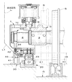
ここで、図1は本発明に係る鉄道車両用軌間可変台車の軌間変更ロック解除装置の一実施形態をロック解除前の狭軌対応状態で示す要部破断正面図、図2は図1に示した軌間変更ロック解除装置の側面図、図3は図1に示した軌間変更ロック解除装置の要部拡大正面図、図4は図1に示した軌間変更ロック解除装置をロック解除状態で示す要部破断正面図、図5は本発明に係る軌間変更ロック解除装置の作動を説明する概略側面図、図6は他の実施形態の係合部材を示す側面図、図7は図6中に示した係合部材のVII−VII破断線に沿った断面図である。
なお、以下の説明においては、上述した従来技術と同一の部分には同じ参照符号を用いるとともに、地上に対する鉛直方向を上下方向と、また鉄道車両の車体幅方向すなわち車軸の軸線方向を左右方向と、鉄道車両の進行方向を前後方向と呼ぶ。
【0015】
まず最初に図1および図2を参照し、本実施形態の軌間変更ロック解除装置を適用する鉄道車両用軌間可変台車の構造を概説すると、軸箱1に対して上下方向に昇降可能に支持された車軸2には、車軸外筒3が車軸2の軸線方向にスライド自在に嵌装されている。そして、この車軸外筒3には、図示されない軸受を介して車輪5が相対回転自在に支持されている。
【0016】
また、前記車軸外筒3の端部に固着されたロッキングブロック6の上面には、一対の係合突起7,8が車軸2の軸線方向に所定の間隔をあけて並置されている。他方、前記軸箱1には、前記係合突起7,8とそれぞれ係合可能な係合孔9と逃げ孔10とがそれぞれ貫設されている。
【0017】
これにより、図1に実線で示したように図示左側の係合突起7と係合孔9とが係合した状態では、ロッキングブロック6すなわち車輪5は狭軌対応状態で軌間変更不能にロックされる。これに対して図示右側の係合突起8と係合孔9とが係合する状態では、図1中に想像線で示したように、車輪5は標準軌対応状態で軌間変更不能にロックされる。
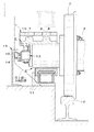
【0018】
一方、図1および図3に示したように、地上Gには車体支持レール20、車体案内レール30およびロック解除レール40が、軌道12と平行に延びるようにそれぞれ配置されている。
【0019】
前記車体支持レール20は、その断面形状が鉛直方向上方に開口したコ字形で、その内部には水平軸21によって回転自在に支持された多数の車体支持ローラ22が、図2に示したように車体支持レール20の長手方向に所定の間隔を開けて配置されている。
【0020】
前記車体案内レール30は、軸箱1が車体支持レール20によって支持された状態で進行する際に、軸箱1が車体支持レール20上からずれたり脱落したりしないように、軸箱1の進行を案内するために設けられている。そして、地上Gから上方に延びる本体部分31の上端部には、軌道12側に開口する凹溝32が凹設されている。
【0021】
前記ロック解除レール40は、本実施形態の軌間変更ロック解除装置を構成する部材で、地上Gから上方に延びる縦壁部分41と、この縦壁部分41の上端部から軌道12側に延設された水平部分42とを有し、かつこの水平部分42の地上Gと対向して延びる下面が係合面43となっている。
【0022】
他方、軸箱1の下端部には、前記車体支持レール20の車体支持ローラ22上を滑走するそり23が、左右方向に延びる支軸24によって揺動自在に支持されている。前記支軸24は複数枚のスペーサ25を介して軸箱1に螺着され、軸箱1に対して上下方向の位置調整が可能となっているので、車輪5の踏面の削正によって車輪5の外径寸法が減少しても、軌間変更の際に前記そり23を確実に車体支持ローラ22上に載置させることができる。
【0023】
また、軸箱1の下端部側面には、前記車体案内レール30の凹溝32内に回転可能に軸着された案内ローラ33に当接する摺板34が螺着されている。これにより、案内ローラ33は左右方向にずれないように軸箱1を案内するので、軸箱1は車体支持レール20上からずれたり脱落したりすることがない。
【0024】
また、車軸2の端部には、軸端梁(軸端部材)50が車軸2に対してその軸線回りに相対回転不能に螺着されている。
この軸端梁50は、図2に示したように、車軸2に外嵌された環状部分51と、この環状部分51から前後方向にそれぞれ延設された前後一対の支持腕52,53とを有している。そして、これらの支持腕52,53には、上方に延びる前後一対のガイドピン54,55がそれぞれ着脱自在に螺着されている。
これらのガイドピン54,55は、軸箱1にそれぞれ貫設されたガイド孔1a,1b内に摺動自在に嵌装されて、車軸2に作用する外力を軸箱1に伝達するとともに、軌間変更時における車軸2の軸箱1に対する昇降を案内する役割を果たしている。
また、前記軸端梁50の環状部分51の最下端部は真っ直ぐ下方に延設され、かつその延設部分56の下面には前記ロック解除レール40と係合可能な係合部材60が螺着されている。
また、前記延設部分56は、軸箱1に取り付けられた防塵カバー70に設けた貫通孔71を貫通して下方に延びている。これにより、軸箱1を前記防塵カバー70で覆って軸箱1内に塵埃が入り込むことを確実に防止できるから、軸箱1内におけるロッキングブロック6の滑らかな昇降動作を保証することができる。
【0025】
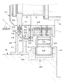
前記係合部材60は、複数枚のスペーサ61を介して前記延設部分56に螺着され、軸端梁50に対する上下方向の位置調整が可能となっている。これにより、車輪5の踏面の削正に伴って車輪5の外径寸法が減少しても、ロック解除レール40に対する係合部材60の上下方向位置を常に一定に保つことができる。
また、この係合部材60は、前記スペーサ61に密着する水平部分62と、この水平部分62の、軌道12側の端部から下方に延設された縦壁部分63と、この縦壁部分63の下端部からロック解除レール40側に延設された係合部分64とから形成され、その構造が簡単であるばかりでなく、十分な強度を有している。 前記係合部分64の上面は、ロック解除レール40の前記係合面43と係合可能な摺動面65とされているが、車輪5が軌道12上を転動しているときにはこの摺動面65と係合面43との間には所定の隙間が存在する。
これに対して、軌間変更時に軸箱1に対して車軸2が降下せずに車輪5が軌道12から浮き上がる異常時には、係合部材60の摺動面65がロック解除レール40の係合面43と摺動する。
さらに、前記摺動面65は、図2に示したように鉛直方向上方に向かって凸な円筒面状に形成されている。これにより、鉄道車両の車体の姿勢変化に伴って軸箱1が車軸2の軸線回りに揺動しても、ロック解除レール40の係合面43との間に所定の隙間が保たれる。そして、この係合部材60は車両限界L内に配置される。
【0026】
次に、ロック解除レール40および係合部材60と車両限界Lとの相対位置関係について図3を参照して説明すると、ロック解除レール40の係合面43は、ロック解除レール40の上端部分であって、かつ車両限界Lのうち地上Gに接近するに連れて軌道12側に接近する傾斜部分L1の近傍に位置するように配置されている。
これにより、ロック解除レール40の上端部がわずかに車両限界の内側に入り込んでいるが、その量はごくわずかであるから、鉄道車両、特に新幹線車両の車体に搭載する各種機器の搭載スペースや搭載位置に与える影響はほとんど無視できる程度である。
【0027】
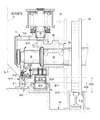
次に、上述のように構成された本実施形態の軌間変更ロック解除装置の作動について図4を参照して説明する。
【0028】
軌間可変台車の軌間変更は、軌道12に対して車体支持レール20、車体案内レール30、ロック解除レール40が並設された軌間変更区間を、軌間可変台車が通過することによって自動的に行われる。
このとき、前記車体支持レール20は前記軌間変更区間の全体において水平に延びる。 これに対して、軌道12は、図5に示したように、車体支持レール20に対して上下方向に所定の間隔H1(図1参照)を開けて水平に延びる第1の水平部分12aと、この第1の水平部分12aの前端から軌間可変台車の進行方向前方に向かって下り勾配を有する傾斜部分12bと、この傾斜部分12bの前端から車体支持レール20に対して上下方向に所定の間隔H2(>H1:図4参照)をあけて水平に延びる第2の水平部分12cとを有している。
また、ロック解除レール40は、軌道12に対して常に上下方向に所定の間隔H3(図1および図4参照)をあけて平行に延びている。
【0029】
図5中に(1)で示したように、軌間可変台車の車輪5が軌道12の第1の水平部分12aにさしかかると、軸箱1の下端に設けられたそり23が車体支持ローラ22上に載り、軸箱1すなわち鉄道車両の車体は車体支持レール20によって支持される。
次いで、この状態で軌間可変台車がさらに前進し、その車輪5が軌道12の前記傾斜部分12bにさしかかると、車輪5は軌道12の降下に伴って軸箱1に対して徐々に下方に相対変位する。
これにより、ロッキングブロック6に設けられた係合突起7,8が軸箱1に貫設された係合孔9から離脱し、図4に示したように車輪5を軌間変更不能に固定するロックが解除される。
このとき、車輪5が軌道12から浮き上がることなく転動するので、係合部材60の摺動面65は、ロック解除レール40の係合面43に対して所定の間隔を開けて対向している。
【0030】
しかしながら、何らかの原因により係合突起7,8と係合孔9とが固着し、若しくは軸端梁50に設けたガイドピン54,55と軸箱1とが固着し、かつその固着力が車輪5を含めた車軸2の重量(約2トン)を上回る異常時には、車軸2が軸箱1に対して降下せず、軸箱1と共に水平に移動を続ける。
したがって、この状態で軌間可変台車の車輪5が軌道12の前記傾斜部分12bに差し掛かると、図5中に(2)で示したように車輪5が軌道12から浮き上がるので、係合部材60の摺動面65がロック解除レール40の係合面43に接触する。
そして、ロック解除レール40の係合面43は、前述したように軌道12の傾斜部分12bと平行に延びており、軌間可変台車の進行方向前方に向かって下り勾配を有するので、軌間可変台車が前進するにつれて係合部材60はロック解除レール40の係合面43と摺動しつつ下方に強制変位させられる。
【0031】
これにより、係合突起7,8と係合孔9とが固着した部分、若しくは軸端梁50に設けたガイドピン54,55と軸箱1とが固着した部分には、車輪5を含めた車軸2の重量に加えて、ロック解除レール40が係合部材60を下方に強制変位させる強制変位力が作用するので、係合突起7,8と係合孔9との固着、若しくは軸端梁50に設けたガイドピン54,55と軸箱1との固着は強制的に解消させられる。
これにより、係合突起7,8が係合孔9から離脱し、図4に示したように車輪5を軌間変更不能に固定するロックは解除される。
【0032】
そして、図5中に(3)で示したように軌間可変台車の車輪5が軌道12上を転動して第2の水平部分12cにさしかかったときには、図4に示したように、係合部材60の摺動面65はロック解除レール40の係合面43に対して所定の隙間を開けて対向し、両者が接触することはない。
【0033】
すなわち、本実施形態の軌間変更ロック解除装置によれば、係合突起7,8と係合孔9との係合が解除できなくなった状態で軌間可変台車の車輪5が軌間変更区間にさしかかった異常時に初めて、係合部材60の摺動面65がロック解除レール40の係合面43と接触して摺動する。
しかしながら、係合突起7,8と係合孔9との係合が通常通りに解除できるときには、係合部材60の摺動面65はロック解除レール40の係合面43と接触しない。
したがって、本実施形態の軌間変更ロック解除装置のように、係合部材60の摺動面65がロック解除レール40の係合面43と摺動する構成としても、その耐久性に問題が生じることはなく、かつその保守点検は容易である。
また、係合部材60の構造は極めて簡単であり、かつ十分な強度を与えることができる。
【0034】
また、本実施形態のロック軌間変更ロック解除装置においては、軸端梁50を下方に延設した延設部分56に係合部材60を取り付ける構成であるから、軌間可変台車のバネ下重量の増加や部品点数の増加を最小限に抑えることができる。
また、車軸2に対する係合部材60の取り付け位置を上下方向に調整することができるから、車輪5の踏面の削正によって車輪5の外径寸法が減少しても、ロック解除レール40に対する係合部材60の上下方向位置を最適位置に保って、ロック解除機能を確実に動作させることができる。
【0035】
次に図6および図7を参照し、上述した係合部材60の一部形状を変形させた係合部材80について説明する。
【0036】
図6および図7に示した係合部材80は、複数枚のスペーサ61を介して前記延設部分56にボルトBで螺着される水平部分81と、この水平部分81の軌道12側の端部から下方に延設されてその内部に左右方向に水平に延びる貫通孔82を形成する湾曲した弾性壁83と、この弾性壁83の下端からロック解除レール40に向かって下方に延設された係合部分84と、この係合部分84の上面に形成されてロック解除レール40の係合面43と係合しつつ摺動する摺動面85とを有している。
【0037】
前記弾性壁83は、ロック解除レール40と係合する係合部分84を、軸端梁50を下方に延設した延設部分56に対して弾性的に支持する役割を果たす。
このため、弾性壁83の肉厚は、この係合部材80がロック解除レール40と係合して軸端梁50を引き下げる場合には、適度に弾性変形しつつ引き下げ力を軸端梁50に伝達できるようにその肉厚tが選定される。
これにより、地上にロック解除レール40の設置するときの精度やスペーサ61の枚数の設定の誤り等の理由によりロック解除レール40が限度以上に係合部材80を引き下げる事態が生じても、弾性壁83が弾性変形するので、係合部材80や軸端梁50等が破損することがない。
【0038】
以上、本発明に係る鉄道車両用軌間可変台車の軌間変更ロック解除装置の一実施形態について詳しく説明したが、本発明は上述した実施形態によって限定されるものではなく、種々の変更が可能であることは言うまでもない。
例えば、上述した実施形態においては、ロック解除レール40と係合部材60とが係合する部分がいずれも断面形状L字形に形成されている。
これに対して、ロック解除レール40の上端部を断面形状「I字形」に形成して左右一対の係合面43,43を設けるとともに、係合部材60にもこれらの係合面43,43とそれぞれ係合する左右一対の摺動面65,65を設けることができる。
【0039】
【発明の効果】
以上の説明から明らかなように、本発明においては、軸端部材を車両限界の近傍まで下方に延設した部分に係合部材を取り付けるとともに、ロック解除レールの係合面をロック解除レールの上端部で前記車両限界のうち地上に接近するに連れて軌道側に傾斜する傾斜部分の近傍に配置するから、ロック解除レールが車両限界の内側に入り込む量を最小限に抑えることができる。
これにより、本発明を新幹線車両に適用する場合でも、車両に搭載する各種機器のスペースを十分に確保することができる。
また、係合部材は、ロック解除レールの係合面と摺動しつつ係合する構成であるから、その構造がきわめて簡単であり、かつ十分な強度を持たせることができる。
また、軌間可変台車の車輪が軌道から浮上しない場合には、ロック解除レールの係合面と係合部材の摺動面とが接触しないから、ロック解除レールおよび係合部材の耐久性を向上させることができ、かつ保守点検も容易である。
また、前記摺動面を鉛直方向上方に向かって凸な曲面に形成するので、鉄道車両の車体の軌道に対する姿勢変化に伴って軸箱が車軸の軸線回りに揺動しても、ロック解除レールの係合面と係合部材の摺動面との間隔を所定の値に保つことができる。
また、軸端部材に対する鉛直方向の取り付け位置を調整する取付調整手段を介して係合部材を軸端部材に取り付けるので、車輪の踏面の削正に伴って車輪の外径寸法が減少しても、ロック解除レールに対する係合部材の上下方向位置を最適に保ってロック解除機能を確実に動作させることができる。
さらに、係合部材に弾性壁を設けたので、ロック解除レールが軸端部材を限度以上に引き下げる事態が生じても、係合部材や軸端部材等が破損することがない。
【図面の簡単な説明】
【図1】本発明に係る鉄道車両用軌間可変台車の軌間変更ロック解除装置の一実施形態をロック解除前の狭軌対応状態で示す要部破断正面図。
【図2】図1に示した軌間変更ロック解除装置の側面図。
【図3】図1に示した軌間変更ロック解除装置の要部拡大正面図。
【図4】図1に示した軌間変更ロック解除装置をロック解除状態で示す要部破断正面図。
【図5】本発明に係る軌間変更ロック解除装置の作動を説明する概略側面図。
【図6】他の実施形態の係合部材を示す側面図。
【図7】図6中に示した係合部材のVII−VII破断線に沿った断面図。
【図8】先願に係る鉄道車両用軌間可変台車を示した要部破断正面図。
【図9】先願に係る軌間変更ロック解除装置を示す要部破断正面図。
【符号の説明】
1 軸箱
2 車軸
3 車軸外筒
4 軸受
5 車輪
6 ロッキングブロック
7,8 係合突起
9 係合孔
10 逃げ孔
11 車体支持レール
12 軌道
13 軸端梁
14 係合ローラ
15 ロック解除レール
16 係合面
20 車体支持レール
21 水平軸
22 車体支持ローラ
23 そり
24 支軸
30 車体案内レール
31 本体部分
32 凹溝
33 案内ローラ
34 摺板
40 ロック解除レール
41 縦壁部分
42 水平部分
43 係合面
50 軸端梁
51 環状部分
52、53 支持腕
54,55 ガイドピン
56 延設部分
60 係合部材
61 スペーサ
62 水平部分
63 縦壁部分
64 係合部分
65 摺動面
70 防塵カバー
71 貫通孔
80 係合部材
81 水平部分
82 貫通孔
83 弾性壁
84 係合部分
85 摺動面[0001]
TECHNICAL FIELD OF THE INVENTION
The present invention relates to a rail-gauge variable bogie that can change the wheel spacing in order to continuously run on rails with different gauge distances, such as a Shinkansen and a conventional line, and more particularly to changing the wheels between rails. BACKGROUND OF THE
[0002]
In Japanese railways, for example, a standard gauge with a gauge of 1435 mm used for Shinkansen and the like and a narrow gauge with a gauge of 1067 mm used for conventional lines and the like are used in combination, but these gauges are different. If a railway vehicle capable of running continuously on a track is developed, the merits such as convenience of passengers, shortening of arrival time, reduction of railway construction cost, and the like are extremely large. In view of this, the applicant of the present application has developed various rail-gauge variable bogies for railway vehicles and has filed applications for them. (See JP-A-8-332950 and others)
[0003]
Referring to FIG. 8, the structure of such a rail-to-rail variable bogie will be described with reference to FIG. 8. The
On the other hand, a pair of
[0004]
As a result, as shown by the solid line in FIG. 8, when the
[0005]
When the gauge is changed from the narrow gauge compatible state to the standard gauge compatible state in the gauge adjustable bogie configured as described above, first, the
Next, when the
Therefore, in this state, by sliding the axle
Thereafter, when the
[0006]
However, in the above-described variable-gauge trolley, if the
[0007]
Therefore, the applicant of the present application has developed a gauge change lock release device for a rail-to-gauge variable bogie that enables the gauge to be smoothly changed by reliably releasing the lock that fixes the wheel so that the gauge cannot be changed. Filed. (See Japanese Patent Application No. 9-147656)
[0008]
An outline of the structure of the lock release device will be described with reference to FIG. 9. An
On the other hand, on the ground G side, a
As a result, when the railroad vehicle enters the gauge change section with the
[0009]
[Problems to be solved by the invention]
By the way, in the above-described rail-change-change lock release device of the rail-rail variable trolley for a railway vehicle (see Japanese Patent Application No. 9-147656), the
On the other hand, the vehicle limit of the Shinkansen vehicle is larger than the first reduced vehicle limit shown in FIG.
Therefore, if the above-described gauge change lock release device is applied to a Shinkansen vehicle as it is, the
In addition, a bearing is used to rotate the
[0010]
Therefore, an object of the present invention is to further improve the gauge change lock release device according to the above-mentioned prior application, and to minimize the amount of entering the inside of the vehicle limit even when applied to a Shinkansen vehicle, and mount it on the vehicle. It is an object of the present invention to provide a gauge change lock release device for a rail gauge variable bogie for a railway vehicle which does not need to change the size and arrangement of various devices, has a simple structure, and is excellent in reliability.
[0011]
[Means for Solving the Problems]
Solving the above issuesThe present invention is a gauge change lock release device for a rail car variable gauge bogie for railway vehicles,
The rail-to-rail variable bogie for railway vehicles,
An axle supported to be able to move up and down with respect to the axle box,
An axle outer cylinder slidably fitted to the axle, which can be locked to the axle box in a position corresponding to the standard gauge and a position corresponding to the narrow gauge so that the gauge distance cannot be changed.
A wheel rotatably supported on the axle outer cylinder via a bearing,
A shaft end beam attached to the shaft end of the axle, which guides the ascending and descending of the axle with respect to the axle box at the time of changing the gauge by a guide pin slidably fitted to the axle box,
An engagement member which is screwed to a portion of the shaft end beam extending downward to near the vehicle limit, and which is disposed inside the vehicle limit,With
When changing the gauge, the lock of the axle outer cylinder with respect to the axle box can be released by displacing the axle downward with respect to the axle box,
And, in the gauge change section on the ground, when the axle is not displaced downward with respect to the axle box at the time of the gauge change, the forward direction in the traveling direction for contacting the engaging member and forcibly displacing the axle downward. An unlocking rail having an engagement surface inclined forward and downward toward the vehicle, and a track on which the wheel rolls are arranged side by side,
Further, the engaging surface of the unlocking rail is disposed at an upper end portion of the unlocking rail so as to be located near an inclined portion approaching the track side as approaching the ground in the vehicle limit. It is characterized by having.
[0012]
Preferably,A curved elastic wall that is screwed to the engaging member at a portion where the shaft end beam extends downward, and a through hole that extends downward from the portion and extends in the left and right direction inside the portion. An engagement portion extending from the elastic wall toward the lock release rail; A sliding surface formed on the upper surface of the engaging portion and sliding while engaging with the engaging surface of the unlocking rail.
Also,The engaging surface of the unlocking rail is arranged so as to be located above the sliding surface of the engaging member at a predetermined interval when the wheel of the variable-gauge trolley does not rise from the track. I do.
Further, the sliding surface of the engagement member is formed as a curved surface that is convex upward in the vertical direction.
Further, the engaging member is attached to the shaft end member via attachment adjusting means for adjusting a vertical attachment position with respect to the shaft end member.
[0013]
That is, according to the present invention, the engaging member is attached to a portion where the shaft end member extends downward to the vicinity of the vehicle limit, and the engaging surface of the unlocking rail is provided at the upper end of the unlocking rail at the vehicle limit.Of the inclined part that inclines toward the orbit as it approaches the groundSince the lock release rail is disposed in the vicinity, it is possible to minimize the amount of the lock release rail entering the inside of the vehicle limit.
As a result, even when the present invention is applied to a Shinkansen vehicle, it is possible to secure a sufficient space for various devices mounted on the vehicle.
Further, since the engagement member is configured to engage with the engagement surface of the lock release rail while sliding, the structure is extremely simple and sufficient strength can be provided.
In addition, when the wheels of the variable rail gauge do not rise from the track, the engagement surface of the unlock rail does not contact the sliding surface of the engagement member, so that the durability of the unlock rail and the engagement member is improved. And maintenance is easy.
Further, since the sliding surface is formed as a curved surface that is convex upward in the vertical direction, even if the axle box swings around the axis of the axle due to a change in the attitude of the railway vehicle with respect to the track, the unlocking rail is provided. The distance between the engaging surface of the first member and the sliding surface of the engaging member can be maintained at a predetermined value.
Further, since the engaging member is attached to the shaft end member via the attachment adjusting means for adjusting the vertical attachment position with respect to the shaft end member, even if the outer diameter of the wheel is reduced as the wheel tread is sharpened. The lock release function can be reliably operated by keeping the vertical position of the engagement member with respect to the lock release rail optimally.
In addition, the engagement memberElastic wallIs provided, even if the lock release rail lowers the shaft end member beyond the limit, the engaging member, the shaft end member and the like are not damaged.
[0014]
BEST MODE FOR CARRYING OUT THE INVENTION
DETAILED DESCRIPTION OF THE PREFERRED EMBODIMENTS Hereinafter, an embodiment of a rail change lock release device for a rail-to-rail variable bogie according to the present invention will be described in detail with reference to FIGS.
Here, FIG. 1 is a fragmentary front view of a main portion showing an embodiment of a gauge change lock releasing device for a rail-to-rail variable bogie according to the present invention in a state corresponding to a narrow gauge before unlocking, and FIG. 2 is shown in FIG. FIG. 3 is a side view of the gauge change lock release device, FIG. 3 is an enlarged front view of a main part of the gauge change lock release device shown in FIG. 1, and FIG. 4 is a main portion showing the gauge change lock release device shown in FIG. 1 in an unlocked state. FIG. 5 is a schematic side view for explaining the operation of the gauge change lock releasing device according to the present invention, FIG. 6 is a side view showing an engaging member of another embodiment, and FIG. 7 is shown in FIG. FIG. 7 is a cross-sectional view of the engagement member taken along a line VII-VII.
In the following description, the same reference numerals will be used for the same parts as the above-described conventional technology, and the vertical direction with respect to the ground will be referred to as the vertical direction, and the vehicle body width direction of the railway vehicle, that is, the axial direction of the axle will be referred to as the left-right direction. The traveling direction of the railway vehicle is referred to as the front-back direction.
[0015]
First, referring to FIG. 1 and FIG. 2, the structure of the rail-to-rail variable bogie to which the rail-to-rail change unlocking device of the present embodiment is applied will be outlined. An axle
[0016]
A pair of
[0017]
Thus, as shown by the solid line in FIG. 1, when the
[0018]
On the other hand, as shown in FIGS. 1 and 3, a vehicle
[0019]
The vehicle
[0020]
When the
[0021]
The
[0022]
On the other hand, a
[0023]
A sliding
[0024]
A shaft end beam (shaft end member) 50 is screwed to the end of the
As shown in FIG. 2, the
These guide pins 54 and 55 are slidably fitted in guide holes 1a and 1b respectively penetrated in the
The lowermost end of the
The extending
[0025]
The engaging
The engaging
On the other hand, when the
Further, as shown in FIG. 2, the sliding
[0026]
Next, the relative positional relationship between the unlocking
As a result, the upper end of the unlocking
[0027]
Next, the operation of the gauge change lock release device of the present embodiment configured as described above will be described with reference to FIG.
[0028]
The change in the gauge of the variable-gauge trolley is automatically performed by the variable-gauge trolley passing through the gauge-change section in which the vehicle body support rails 20, the vehicle body guide rails 30, and the lock release rails 40 are arranged side by side with respect to the
At this time, the vehicle
The
[0029]
As shown by (1) in FIG. 5, when the
Next, in this state, the gauge-adjustable trolley further moves forward, and when its
As a result, the
At this time, since the
[0030]
However, the engaging
Therefore, in this state, when the
As described above, the
[0031]
Thus, the
As a result, the
[0032]
Then, when the
[0033]
That is, according to the gauge change lock release device of the present embodiment, the
However, when the engagement between the
Therefore, even if the sliding
Further, the structure of the
[0034]
In addition, in the lock gauge change lock release device of the present embodiment, since the engaging
Further, since the mounting position of the engaging
[0035]
Next, with reference to FIGS. 6 and 7, a description will be given of an
[0036]
The engaging
[0037]
The
For this reason, the thickness of the
Accordingly, even if the unlocking
[0038]
As mentioned above, although one Embodiment of the gauge change lock release apparatus of the gauge variable bogie for railway vehicles which concerns on this invention was described in detail, this invention is not limited to said embodiment, Various changes are possible. Needless to say.
For example, in the above-described embodiment, the portions where the unlocking
On the other hand, the upper end of the
[0039]
【The invention's effect】
As is apparent from the above description, in the present invention, the engaging member is attached to the portion where the shaft end member extends downward to the vicinity of the vehicle limit, and the engaging surface of the unlocking rail is connected to the upper end of the unlocking rail. Of the vehicle limitOf the inclined part that inclines toward the orbit as it approaches the groundSince the lock release rail is disposed in the vicinity, it is possible to minimize the amount of the lock release rail entering the inside of the vehicle limit.
As a result, even when the present invention is applied to a Shinkansen vehicle, it is possible to secure a sufficient space for various devices mounted on the vehicle.
Further, since the engagement member is configured to engage with the engagement surface of the lock release rail while sliding, the structure is extremely simple and sufficient strength can be provided.
In addition, when the wheels of the variable rail gauge do not rise from the track, the engagement surface of the unlock rail does not contact the sliding surface of the engagement member, so that the durability of the unlock rail and the engagement member is improved. And maintenance is easy.
Further, since the sliding surface is formed as a curved surface that is convex upward in the vertical direction, even if the axle box swings around the axis of the axle due to a change in the attitude of the railway vehicle with respect to the track, the unlocking rail is provided. The distance between the engaging surface of the first member and the sliding surface of the engaging member can be maintained at a predetermined value.
Further, since the engaging member is attached to the shaft end member via the attachment adjusting means for adjusting the vertical attachment position with respect to the shaft end member, even if the outer diameter of the wheel is reduced as the wheel tread is sharpened. The lock release function can be reliably operated by keeping the vertical position of the engagement member with respect to the lock release rail optimally.
In addition, the engagement memberElastic wallSince the lock release rail lowers the shaft end member more than the limit, the engagement member and the shaft end member are not damaged.
[Brief description of the drawings]
FIG. 1 is a fragmentary front elevational view showing an embodiment of a rail-change lock release device for a rail-gauge variable bogie according to the present invention in a narrow-gauge compatible state before lock release.
FIG. 2 is a side view of the gauge change lock release device shown in FIG. 1;
FIG. 3 is an enlarged front view of a main part of the gauge change lock release device shown in FIG. 1;
FIG. 4 is a fragmentary front view showing the gauge change lock release device shown in FIG. 1 in an unlocked state.
FIG. 5 is a schematic side view for explaining the operation of the gauge change lock release device according to the present invention.
FIG. 6 is a side view showing an engagement member according to another embodiment.
7 is a cross-sectional view of the engagement member shown in FIG. 6, taken along the line VII-VII.
FIG. 8 is a fragmentary front view of a main part showing the rail-to-rail variable bogie according to the prior application.
FIG. 9 is a fragmentary front view showing a gauge change lock release device according to the prior application.
[Explanation of symbols]
1 axle box
2 axles
3 axle outer cylinder
4 Bearing
5 wheels
6 Locking block
7,8 engagement projection
9 Engagement hole
10 Escape hole
11 Body support rail
12 orbits
13 Shaft end beam
14 Engaging roller
15 Lock release rail
16 Engagement surface
20 Body support rail
21 horizontal axis
22 Body support rollers
23 Sledding
24 spindle
30 Body guide rail
31 Body
32 groove
33 Guide roller
34 Slipboard
40 Lock release rail
41 Vertical wall part
42 horizontal part
43 engagement surface
50 Shaft end beam
51 Annular part
52, 53 Support arm
54, 55 Guide pin
56 Extension
60 engagement member
61 Spacer
62 horizontal part
63 vertical wall
64 engagement part
65 Sliding surface
70 Dustproof cover
71 Through hole
80 Engaging member
81 horizontal part
82 Through hole
83 Elastic wall
84 engagement part
85 sliding surface
Claims (5)
前記鉄道車両用軌間可変台車が、
軸箱に対して上下方向に昇降可能に支持された車軸と、
標準軌に対応する位置および狭軌に対応する位置においてそれぞれ前記軸箱に対して軌間変更不能にロック可能な、前記車軸にスライド自在に嵌装された車軸外筒と、
前記車軸外筒に軸受を介して回転可能に支持された車輪と、
前記軸箱に摺動自在に嵌装されたガイドピンにより軌間変更時における前記車軸の前記軸箱に対する昇降を案内する、前記車軸の軸端に取り付けられた軸端梁と、
前記軸端梁を車両限界の近傍まで下方に延設した部分に螺着されて、前記車両限界の内側に配置された係合部材と、
を備え、
軌間変更時には前記車軸を前記軸箱に対して下方に変位させることにより前記軸箱に対する前記車軸外筒のロックを解除できるようになっており、
かつ地上の軌間変更区間には、軌間変更時に前記車軸が前記軸箱に対して下方に変位しないときには前記係合部材に接触して前記車軸を強制的に下方に変位させるための前記進行方向前方に向かって前下がりに傾斜する係合面を有したロック解除レールと、前記車輪がその上を転動する軌道とが並設されており、
さらに前記ロック解除レールの係合面は、前記ロック解除レールの上端部分で、前記車両限界のうち地上に接近するに連れて前記軌道側に接近する傾斜部分の近傍に位置するように配置されている、
ことを特徴とする鉄道車両用軌間可変台車のための軌間変更ロック解除装置。 A gauge change lock release device for a rail gauge variable bogie for a railway vehicle,
The rail-to-rail variable bogie for railway vehicles,
An axle supported to be able to move up and down with respect to the axle box,
An axle outer cylinder slidably fitted to the axle, which can be locked to the axle box in a position corresponding to the standard gauge and a position corresponding to the narrow gauge so that the gauge distance cannot be changed.
A wheel rotatably supported on the axle outer cylinder via a bearing,
A shaft end beam attached to the shaft end of the axle, which guides the ascending and descending of the axle with respect to the axle box at the time of changing the gauge by a guide pin slidably fitted to the axle box,
An engagement member which is screwed to a portion of the shaft end beam extending downward to near the vehicle limit, and which is disposed inside the vehicle limit,
With
When changing the gauge, the lock of the axle outer cylinder with respect to the axle box can be released by displacing the axle downward with respect to the axle box,
And, in the gauge change section on the ground, when the axle is not displaced downward with respect to the axle box at the time of the gauge change, the forward direction in the traveling direction for contacting the engaging member and forcibly displacing the axle downward. An unlocking rail having an engagement surface inclined forward and downward toward the vehicle, and a track on which the wheel rolls are arranged side by side,
Further, the engaging surface of the unlocking rail is disposed at an upper end portion of the unlocking rail so as to be located near an inclined portion approaching the track side as approaching the ground in the vehicle limit. Yes,
A rail change lock release device for a rail-gauge variable bogie for a railway vehicle.
Priority Applications (1)
| Application Number | Priority Date | Filing Date | Title |
|---|---|---|---|
| JP34386999A JP3588024B2 (en) | 1999-12-02 | 1999-12-02 | Rail change lock release device for rail-to-rail variable bogies for railway vehicles |
Applications Claiming Priority (1)
| Application Number | Priority Date | Filing Date | Title |
|---|---|---|---|
| JP34386999A JP3588024B2 (en) | 1999-12-02 | 1999-12-02 | Rail change lock release device for rail-to-rail variable bogies for railway vehicles |
Publications (2)
| Publication Number | Publication Date |
|---|---|
| JP2001158351A JP2001158351A (en) | 2001-06-12 |
| JP3588024B2 true JP3588024B2 (en) | 2004-11-10 |
Family
ID=18364877
Family Applications (1)
| Application Number | Title | Priority Date | Filing Date |
|---|---|---|---|
| JP34386999A Expired - Fee Related JP3588024B2 (en) | 1999-12-02 | 1999-12-02 | Rail change lock release device for rail-to-rail variable bogies for railway vehicles |
Country Status (1)
| Country | Link |
|---|---|
| JP (1) | JP3588024B2 (en) |
Families Citing this family (2)
| Publication number | Priority date | Publication date | Assignee | Title |
|---|---|---|---|---|
| CN108674443B (en) * | 2018-06-12 | 2024-01-30 | 吉林大学 | Ground supporting vertical bearing device suitable for variable gauge bogie |
| KR102932131B1 (en) * | 2021-12-14 | 2026-02-27 | 한국철도기술연구원 | Gauge-changeable bogie for railway vehicle |
Family Cites Families (7)
| Publication number | Priority date | Publication date | Assignee | Title |
|---|---|---|---|---|
| JP3470986B2 (en) * | 1995-02-13 | 2003-11-25 | 財団法人鉄道総合技術研究所 | Rail-to-rail variable bogie for railway vehicles |
| JP3265153B2 (en) * | 1995-06-06 | 2002-03-11 | 日本鉄道建設公団 | Rail-to-rail variable bogies for railway vehicles |
| ES2130039B1 (en) * | 1996-04-17 | 2000-02-16 | Talgo Patentes | RAILWAY AXLE ASSEMBLY EQUIPPED WITH AUTOMATIC CHANGE OF TRACK WIDTH AND ADAPTABLE TO CONVENTIONAL BOGIES OF GOODS. |
| JP3558782B2 (en) * | 1996-06-14 | 2004-08-25 | 財団法人鉄道総合技術研究所 | Rail-to-rail variable bogie for railway vehicles |
| JPH1035941A (en) * | 1996-07-18 | 1998-02-10 | Mita Ind Co Ltd | Transfer paper carrying mechanism of image forming device |
| JP3845970B2 (en) * | 1996-11-13 | 2006-11-15 | ブラザー工業株式会社 | Ink jet device |
| JP3499401B2 (en) * | 1997-06-05 | 2004-02-23 | 富士重工業株式会社 | Rail-change lock release device for rail-gauge variable bogies for railway vehicles |
-
1999
- 1999-12-02 JP JP34386999A patent/JP3588024B2/en not_active Expired - Fee Related
Also Published As
| Publication number | Publication date |
|---|---|
| JP2001158351A (en) | 2001-06-12 |
Similar Documents
| Publication | Publication Date | Title |
|---|---|---|
| EP0596408B1 (en) | Method of changing the gauge of a railway vehicle, variable gauge railway vehicle, and ground facility therefore | |
| JP3652577B2 (en) | Rail vehicle variable gauge truck | |
| JP2502911B2 (en) | Railcar bogie | |
| JP6446293B2 (en) | Rail vehicle variable gauge truck | |
| AU2009242050B2 (en) | Variable-width bogie with rotating axles and a stationary apparatus for changing track width | |
| JP5428117B2 (en) | Adjustable rail / gauge truck and rail / gauge change station | |
| RU2567679C2 (en) | Adjustable wheeled truck for railway cars | |
| AU683686B2 (en) | A guiding system applicable to a four-wheel bogie with variable gap between them | |
| JP3470986B2 (en) | Rail-to-rail variable bogie for railway vehicles | |
| JP3588024B2 (en) | Rail change lock release device for rail-to-rail variable bogies for railway vehicles | |
| EP0884231A1 (en) | Rolling monoaxle provided with movable independent wheels for articulated railway carriages intended to the transportation of cars | |
| US7254896B2 (en) | Inner bearing split axle assembly | |
| KR100969195B1 (en) | Device for preventing a train from derailing | |
| EP0611847B1 (en) | Fixed installation for changing the railways gage | |
| JP3588023B2 (en) | Rail-to-rail variable bogie for railway vehicles | |
| JP3652570B2 (en) | Rail vehicle variable gauge truck | |
| JP3499401B2 (en) | Rail-change lock release device for rail-gauge variable bogies for railway vehicles | |
| JPH08169338A (en) | Variable gage bogie and gage changer device for rolling stock | |
| JP4226975B2 (en) | Railway transport cart | |
| JP2003137093A (en) | Lock release device for rail-to-rail variable bogies for railway vehicles | |
| KR102844179B1 (en) | Gauge-changeable system for railway vehicle and guage changing method using the system | |
| JP3678947B2 (en) | How to change the gauge and equipment for changing the gauge | |
| JPH07267080A (en) | Vehicle | |
| JPS5852858B2 (en) | Extremely small radius traveling trolley | |
| JPS6021109B2 (en) | Railway vehicle trolley |
Legal Events
| Date | Code | Title | Description |
|---|---|---|---|
| A977 | Report on retrieval |
Free format text: JAPANESE INTERMEDIATE CODE: A971007 Effective date: 20040129 |
|
| A131 | Notification of reasons for refusal |
Free format text: JAPANESE INTERMEDIATE CODE: A131 Effective date: 20040213 |
|
| A521 | Written amendment |
Free format text: JAPANESE INTERMEDIATE CODE: A523 Effective date: 20040413 |
|
| TRDD | Decision of grant or rejection written | ||
| A01 | Written decision to grant a patent or to grant a registration (utility model) |
Free format text: JAPANESE INTERMEDIATE CODE: A01 Effective date: 20040716 |
|
| A61 | First payment of annual fees (during grant procedure) |
Free format text: JAPANESE INTERMEDIATE CODE: A61 Effective date: 20040811 |
|
| R150 | Certificate of patent or registration of utility model |
Free format text: JAPANESE INTERMEDIATE CODE: R150 |
|
| FPAY | Renewal fee payment (event date is renewal date of database) |
Free format text: PAYMENT UNTIL: 20070820 Year of fee payment: 3 |
|
| FPAY | Renewal fee payment (event date is renewal date of database) |
Free format text: PAYMENT UNTIL: 20080820 Year of fee payment: 4 |
|
| FPAY | Renewal fee payment (event date is renewal date of database) |
Free format text: PAYMENT UNTIL: 20090820 Year of fee payment: 5 |
|
| FPAY | Renewal fee payment (event date is renewal date of database) |
Free format text: PAYMENT UNTIL: 20100820 Year of fee payment: 6 |
|
| FPAY | Renewal fee payment (event date is renewal date of database) |
Free format text: PAYMENT UNTIL: 20100820 Year of fee payment: 6 |
|
| FPAY | Renewal fee payment (event date is renewal date of database) |
Free format text: PAYMENT UNTIL: 20110820 Year of fee payment: 7 |
|
| FPAY | Renewal fee payment (event date is renewal date of database) |
Free format text: PAYMENT UNTIL: 20110820 Year of fee payment: 7 |
|
| S533 | Written request for registration of change of name |
Free format text: JAPANESE INTERMEDIATE CODE: R313533 |
|
| FPAY | Renewal fee payment (event date is renewal date of database) |
Free format text: PAYMENT UNTIL: 20110820 Year of fee payment: 7 |
|
| R350 | Written notification of registration of transfer |
Free format text: JAPANESE INTERMEDIATE CODE: R350 |
|
| FPAY | Renewal fee payment (event date is renewal date of database) |
Free format text: PAYMENT UNTIL: 20110820 Year of fee payment: 7 |
|
| FPAY | Renewal fee payment (event date is renewal date of database) |
Free format text: PAYMENT UNTIL: 20120820 Year of fee payment: 8 |
|
| FPAY | Renewal fee payment (event date is renewal date of database) |
Free format text: PAYMENT UNTIL: 20120820 Year of fee payment: 8 |
|
| FPAY | Renewal fee payment (event date is renewal date of database) |
Free format text: PAYMENT UNTIL: 20130820 Year of fee payment: 9 |
|
| LAPS | Cancellation because of no payment of annual fees |