JP3600007B2 - Cooler and method of manufacturing the same - Google Patents
Cooler and method of manufacturing the same Download PDFInfo
- Publication number
- JP3600007B2 JP3600007B2 JP10461798A JP10461798A JP3600007B2 JP 3600007 B2 JP3600007 B2 JP 3600007B2 JP 10461798 A JP10461798 A JP 10461798A JP 10461798 A JP10461798 A JP 10461798A JP 3600007 B2 JP3600007 B2 JP 3600007B2
- Authority
- JP
- Japan
- Prior art keywords
- cooler
- air
- fins
- wide
- cut
- Prior art date
- Legal status (The legal status is an assumption and is not a legal conclusion. Google has not performed a legal analysis and makes no representation as to the accuracy of the status listed.)
- Expired - Fee Related
Links
Images



Classifications
-
- F—MECHANICAL ENGINEERING; LIGHTING; HEATING; WEAPONS; BLASTING
- F25—REFRIGERATION OR COOLING; COMBINED HEATING AND REFRIGERATION SYSTEMS; HEAT PUMP SYSTEMS; MANUFACTURE OR STORAGE OF ICE; LIQUEFACTION SOLIDIFICATION OF GASES
- F25B—REFRIGERATION MACHINES, PLANTS OR SYSTEMS; COMBINED HEATING AND REFRIGERATION SYSTEMS; HEAT PUMP SYSTEMS
- F25B2500/00—Problems to be solved
- F25B2500/01—Geometry problems, e.g. for reducing size
Landscapes
- Cold Air Circulating Systems And Constructional Details In Refrigerators (AREA)
Description
【0001】
【発明の属する技術分野】
この発明は、ファン装置によって冷気を庫内に強制循環させる冷蔵庫等に用いる冷却器に関する。
【0002】
【従来の技術】
図12は、従来の冷却器を用いた冷蔵庫の本体中部の縦断面図、図13は図12の冷却器の斜視図、図14はこの従来の冷却器の速度分布の試験結果である。
図12において、1は冷蔵庫本体、2は内箱、3、4、5は、庫内を中仕切6、7で上下に仕切って形成された冷凍室、冷蔵室、野菜室、8は冷却器、9は冷凍室3の背面と冷却器8を設置した冷却器室10とを仕切るファングリル、11は冷却器室10の上部に配置したファン、12は冷凍室3への冷気吹出口、13は冷凍室3からの冷気吸込口、14は冷蔵室4に冷気を吹出させる吹出ダクト、15は中仕切7内を通って冷却器室10に空気を吸込ませる吸込ダクト、16は冷却器室10の冷却器8下方に設置した霜取ヒータである。
【0003】
上記冷却器8は図13に示すように、複数列の蛇行状に曲げた冷媒パイプ8aに直交させて、高さ方向と幅方向の寸法が長い広幅フィン8bと、高さ方向と幅方向の寸法が短い狭幅フィン8cとが空気の流れの入口側である冷却器8下部で広幅フィン8bと狭幅フィン8cとをずらし交互に配列してある。
【0004】
広幅フィン8bと狭幅フィン8cの幅方向両外側には、広幅フィン8bと狭幅フィン8cの幅方向の寸法の差によりバイパス風路17a、17bが形成され、広幅フィン8b幅方向両外側上部には、バイパス風路17a、17b内を流れる空気に抵抗する方向に、切起し片18が4ヶ所形成されている。
【0005】
従来の冷却器を組み込んだ冷蔵庫は以上のように構成され、冷却器8で冷却された冷気はファン11の駆動により、一部が冷気吹出口12から冷凍室3に送り出され、冷気吸込口13から冷却器室10に戻され、残りが吹出しダクト14から冷蔵室4へ送り出され、野菜室5内の吸込みダクト15から冷却器室10に戻される強制循環をしている。
【0006】
冷蔵庫の冷却運転中に、冷凍室3、冷蔵室4、野菜室5の扉を開閉する都度、外部から湿気が冷蔵庫内部に進入し、この湿気は、熱交換の後に冷却器8、特に広幅フィン8b、狭幅フィン8cの前縁部および冷媒パイプ8aに霜として多く付着する。そこで冷却器8は、着霜に伴う通風面積の減少による庫内の冷却性能の著しい低下を防止するため、着霜時にはバイパス風路17a、17bを空気が流れるようにしており、さらにフィン間隔が狭く接触面積が大きい冷却器中央部分及び冷媒パイプ8a周囲を空気が流れるように、バイパス風路17a、17b内を流れる空気に対して抵抗する方向に、切起し片18が4ヶ所形成されている。
【0007】
【発明が解決しようとする課題】
従来の冷却器は、上述のように構成されているため、図14の試験結果に示すように、着霜量が多い時、少ない時に関わらず空気抵抗の少ないバイパス風路17a、17b内により多く空気が流れており、冷却器8中央部では熱交換が多く行われず、冷却器8中央部及び冷媒パイプ8a周囲を空気が流れる様に設けられた広幅フィン8b幅方向両外側上部の4ヶ所の切起し片18は、冷却器8上部においてのみ効果を出しており、冷却器8全体の熱交換量の増加への寄与は少ない。
【0008】
この発明は、かかる問題点を解決するためになされたもので、冷却器への着霜の有無によらず、熱交換量を改善し、熱交換性能が良好な冷却器及びその製造方法を提供することを目的とする。
【0009】
【課題を解決するための手段】
この発明に係る冷却器は、千鳥状に配列された冷媒パイプと、この冷媒パイプと直交するように設けられ、空気の流れ方向の寸法が長い広幅フィンと、冷媒パイプと直交するように設けられ、広幅フィンと交互に配列され、空気の流れ方向の寸法が短い狭幅フィンと、広幅フィンの幅方向両外側部を狭幅フィンの幅方向両外側から突出させることにより、広幅フィンと狭幅フィンとの幅方向の両外側部の間に形成されるバイパス風路と、広幅フィンの狭幅フィンの幅方向両外側部において、空気の流れ方向に対する高さ位置が、冷媒パイプと同じ設置位置(等ピッチの位置)で、かつ広幅フィンの幅方向両外縁部と冷媒パイプとの距離が最も広い側に設けられ、空気の流れを冷却器中央部に導く風路偏向部材とを備えたものである。
【0010】
また、風路偏向部材を、空気の流れに抵抗する方向に折り曲げられた切り起し片で構成したものである。
【0011】
また、風路偏向部材を、凹凸形状の凹凸形状部材で構成したものである。
【0012】
また、風路偏向部材を、バーリング加工されたバーリング形状部材で構成したものである。
【0013】
また、広幅フィンの幅方向両外側部に、プラスチック部品もしくは板金部品により成形された前記切り起し片を有する部品を設けたものである。
【0014】
また、狭幅フィンを冷却器幅方向の左右に偏らせて配列させたものである。
【0015】
また、切り起し片を、広幅フィンの幅方向中央上方に向かって傾斜させたものである。
【0016】
また、空気の流れ方向に対する高さ位置に対して最下段の風路偏向部材まで、冷却器の前後の少なくとも一方に別のバイパス風路を設けたものである。
【0017】
この発明に係る冷却器の製造方法は、広幅フィンに備えられた切り起し片の切り起し加工と、切り起し片のカット加工とを、同時加工にて行うものである。
【0018】
【発明の実施の形態】
実施の形態1.
以下、この発明の実施の形態1を図面を参照して説明する。
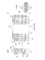
図1はこの発明の実施の形態1に係る冷却器を使用した冷蔵庫本体中部の縦断側面図、図2は図1の冷却器の斜視図、図3は切起し片を示す図、図4は実施の形態1の冷却器の試験結果を示す図である。
【0019】
図1、図2において、1は冷蔵庫本体、2は内箱、3、4、5は、庫内を中仕切6、7で上下に仕切って形成された冷凍室、冷蔵室、野菜室、8は冷却器、9は冷凍室3の背面と冷却器8を設置した冷却器室10とを仕切るファングリル、11は冷却器室10の上部に配置したファン、12は冷凍室3への冷気吹出口、13は冷凍室3からの冷気吸込口、14は冷蔵室4に冷気を吹出させる吹出ダクト、15は中仕切7内を通って冷却器室10に空気を吸込ませる吸込ダクト、16は冷却器室10の冷却器8下方に設置した霜取ヒータである。
【0020】
冷媒パイプ8a、板状の空気の流れ方向の寸法の長い広幅フィン8b、空気の流れ方向の寸法の短い狭幅フィン8cは従来のものと同様であり、交互に、千鳥状に配列された冷媒パイプ8aに直交させて、多数枚ずつ配置してあり、広幅フィン8b、狭幅フィン8cを空気の入口側となる幅方向にずらし、狭幅フィン8cの両外側縁から広幅フィン8bの両外側部幅方向に突出させてある。
【0021】
広幅フィン8bには、上記狭幅フィン8cの幅方向両外側部に、空気の流れ方向に対する高さ位置が、冷媒パイプ8aと同じ設置位置(等ピッチの位置)で、かつ上記広幅フィン8bの幅方向両外縁部と冷媒パイプ8cとの距離が最も広い側のみに、空気の流れに抵抗する方向に、同一方向に折り曲げられた複数の切起し片20を風路偏向部材として備えている。
【0022】
切起し片20は、図3に示すように取り付けられている。広幅フィン8bに取り付けられた切起し片20の位置は、切起したときの広幅フィン8bからの出代が、その切起し方向にある隣の広幅フィン8b’と、丁度接する寸法、もしくはある程度クリアランスを空けて、バイパス風路17a、17bを完全に塞がない形状に形成する。
また広幅フィン8b幅方向位置では、狭幅フィン8cとの位置は、丁度接する寸法、もしくはある程度クリアランスをもってバイパス風路17a、17bを完全に塞がない形状に形成する。
【0023】
上記のように構成した実施の形態1の冷却器は、図4の試験結果に示すように、空気の流れ方向に沿って、広幅フィン8bの外側部によって形成されるバイパス風路17a、17bを流れる空気が、切り起し片20によって冷却器8の中央部へ導かれる。
【0024】
空気の流れ方向下側(冷却器8下側)から空気が冷却器8中央部へ導かれるため、空気が接触するフィン面積、および冷媒パイプ8aの表面積が大きくとれて良好な熱交換性能が得られる。
【0025】
さらに切り起し片20が、空気の流れ方向に対する高さ位置が、冷媒パイプ8aと同じ設置位置(等ピッチの位置)で、かつ上記広幅フィン8bの幅方向両外縁部と冷媒パイプ8aとの距離が最も広い側のみに設けられているため、バイパス風路17a、17bを完全に塞いでなく、かつ、熱交換に有効なフィン表面積は減少していないのでフィン効率は下がっていない。
【0026】
また、着霜時に冷却器8下側で目詰まりが発生しても、バイパス風路17a、17bを通過する空気は冷却器8中央部に流れ、空気が接触するフィン面積、および冷媒パイプ8aの表面積が大きくなり、熱交換性能は従来の冷却器に比べて確実に向上する(冷却器室10の吸込み口13と吹出し口12との温度差が約1.5degから2deg増加。)。
さらに、冷却器8温度と冷凍室3内温度の温度差が減少し消費電力量が減少する。
【0027】
上述の実施の形態1の冷却器を使用した冷蔵庫の性能を従来のものと比較すると、表1のようになる。
【0028】
【表1】

実施の形態2.
以下、この発明の実施の形態2を図面を参照して説明する。
図5はこの発明の実施の形態2に係る冷却器を使用した冷蔵庫の中央部の正面図、図6は図5の冷却器の斜視図である。
【0030】
8は冷却器、冷媒パイプ8a、板状の空気の流れ方向の寸法の長い広幅フィン8b、空気の流れ方向の寸法の短い狭幅フィン8cは従来のものと同様であり、冷却器8の両側に狭幅フィン8cを片寄らせて、冷却器8中央に広幅フィン8bを偏らせて千鳥状に配列された冷媒パイプ8aに直交させ、多数枚ずつ配置してあり、広幅、狭幅のフィン8b、8cを空気の入口側となる幅方向にずらし、狭幅フィン8cの両外側縁から広幅フィン8bの両外側部幅方向に突出させてある。
【0031】
広幅フィン8bは、上記狭幅フィン8cの幅方向両外側部に、空気の流れ方向に対する高さ位置が、冷媒パイプ8aと同じ設置位置(等ピッチの位置)で、かつ上記広幅フィン8bの幅方向両外縁部と冷媒パイプ8cとの距離が最も広い側のみに、空気の流れに抵抗する方向に、同一方向に折り曲げられた複数の切起し片20を備えている。
【0032】
上記のように構成した実施の形態2の冷却器は、実施の形態1と同様の効果が得られる。空気の流れ方向に沿って、広幅フィン8bの外側部によって形成されるバイパス風路17a、17b内を流れる空気が、切り起し片20によって冷却器8の中央部へ導かれ、空気の流れ方向下側(冷却器8下側)から空気が冷却器8中央部へ導かれるため、空気が接触するフィン面積、および冷媒パイプ8aの表面積が大きくとれて良好な熱交換性能が得られる。
【0033】
冷却器8は、冷却器8の左右両側の空気戻り風路21a、21bから、冷却器室10への間口と同じ断面積分の空間を左右に保つように、冷却器8の左右両側の上方に狭幅フィン8cを片寄らせることにより、冷却器8の左右両側の空気戻り風路21a、21bの抵抗とならず、冷蔵庫内部の強制循環をスムースに行うことが出来る。
【0034】
実施の形態3.
以下、この発明の実施の形態3を図面を参照して説明する。
図7はこの発明の実施の形態3に係る冷却器の斜視図である。
図において、8は冷却器、冷媒パイプ8a、板状の空気の流れ方向の寸法の長い広幅フィン8b、空気の流れ方向の寸法の短い狭幅フィン8cは実施の形態1と同様であり、交互に、千鳥状に配列された冷媒パイプ8aに直交させて、多数枚ずつ配置してあり、広幅フィン8b、狭幅フィン8cを空気の入口側となる幅方向にずらし、狭幅フィン8cの両外側縁から広幅フィン8bの両外側部幅方向に突出させ、広幅フィン8bには、上記狭幅フィン8cの幅方向両外側部に、空気の流れ方向に対する高さ位置が、冷媒パイプと同じ設置位置(等ピッチの位置)で、上記広幅フィン8bの幅方向両外縁部と冷媒パイプ8cとの距離が最も広い側のみに、幅方向中央上方に向けて、空気の流れに抵抗する方向に、同一方向に折り曲げられた複数の切起し片20を備えている。
【0035】
広幅フィン8bの外側部によって形成されるバイパス風路内を流れる空気が、幅方向中央上方に向けて形成された切り起し片20によって、水平に設けた場合に比べてより滑らかに冷却器8の中央部へ導かれ、冷却器8内部を通過する単位時間内の風量が増加し、冷蔵庫内部の強制循環がより滑らかに行われ、消費電力量の削減につながる。
上記以外の構成及び得られる効果は、実施の形態1と同一である。
【0036】
実施の形態4.
以下、この発明の実施の形態4を図面を参照して説明する。
図8はこの発明の実施の形態4に係る冷却器の側面図である。
図8に示すように、広幅フィン8bに、切起し片のかわりに金型加工により風路偏向部材である凹凸形状部材(ビード形状)25を取付ける場合、四角形状の切り起しでは2工程になるのに比べて、凹凸形状部材(ビード形状)25では工程が不要となり、工数が削減され、加工費削減につながる。
上記以外の構成及び得られる効果は、実施の形態1と同一である。
【0037】
実施の形態5.
以下、この発明の実施の形態5を図面を参照して説明する。
図9はこの発明の実施の形態5に係る冷却器の側面図である。
図9に示すように、広幅フィン8bに、風路偏向部材として切起し片の代わりに金型加工によりバーリング形状部材26を取付ける場合、切り起し片では2工程になるのに比べて、バーリング形状部材26では1工程となり、工数が削減され、加工費削減につながる。
上記以外の構成及び得られる効果は、実施の形態1と同一である。
【0038】
実施の形態6.
以下、この発明の実施の形態6を図面を参照して説明する。
図10はこの発明の実施の形態6に係る冷却器を使用した冷蔵庫本体中部の縦断側面図である。
図10において、広幅フィン8bに切起し片20を取付け、さらに冷却器8背面の内箱2を抉り取る形でバイパス風路17c(図10(b))、もしくはファングリル9を抉り取る形でバイパス風路17d(図10(c))、もしくは共にバイパス風路17c、17d(図10(a))を設けている。
【0039】
空気が接触する広幅フィン8b、狭幅フィン8cの下部前縁部および冷媒パイプ8aに着霜時、バイパス風路17cもしくはバイパス風路17d、もしくは同時にバイパス風路17c、17dを通過した空気を冷却器8へ導き、かつバイパス風路17c、17dの上端は、冷却器8に設けた切り起し片20の中で最下の切り起し片20a、20bの位置に合わせており、冷却器8に導かれた空気は切起し20a、20bによってさらに冷却器8内部へと導かれ、空気が接触するフィン面積、および冷媒パイプ8aの表面積が大きくとれて良好な熱交換性能が得られる。
上記以外の構成及び得られる効果は、実施の形態1と同一である。
【0040】
実施の形態7.
以下、この発明の実施の形態7を図面を参照して説明する。
図11はこの発明の実施の形態7に係る冷却器の斜視図、および冷却器に取付ける切り起し形状別部品を示す図である。
図において、8は冷却器、冷媒パイプ8a、板状の空気の流れ方向の寸法の長い広幅フィン8b、空気の流れ方向の寸法の短い狭幅フィン8cは従来のものと同様であり、交互に、千鳥状に配列された冷媒パイプ8aに直交させて、多数枚ずつ配置してあり、広幅、狭幅フィン8b、8cを空気の入口側となる幅方向にずらして、狭幅フィン8cの両外側縁から広幅フィン8bの両外側部幅方向に突出させ、広幅フィン8bには上記狭幅フィン8cの幅方向両外側部に、空気の流れ方向に対する高さ位置が、冷媒パイプと同じ設置位置(等ピッチの位置)で、かつ上記広幅フィン8bの幅方向両外縁部と冷媒パイプ8cとの距離が最も広い側のみに、空気の流れに抵抗する方向に、同一方向に複数の切起し片23を備えているプラスチック部品24a、もしくは板金部品24bを取付けている。
上記以外の構成及び得られる効果は、実施の形態1と同一である。
【0041】
【発明の効果】
この発明に係る冷却器は、空気の流れ方向に沿って広幅フィンの外側部によって形成されるバイパス風路内を流れる空気が、風路偏向部材によって冷却器中央部へ導かれ、空気の流れ方向下側(冷却器下側)から空気が冷却器中央部へ導かれるため、空気が接触するフィン面積、および冷媒パイプの表面積が大きくとれて良好な熱交換性能が得られる。
さらに風路偏向部材が、空気の流れ方向に対する高さ位置が、冷媒パイプと同じ設置位置(等ピッチの位置)で、かつ広幅フィンの幅方向両外縁部と冷媒パイプとの距離が最も広い側に設けられているため、完全にバイパス風路を塞いでおらず、熱交換に有効なフィン面積は減少しておらず、フィン効率は減っていない。
また着霜時に冷却器下側で目詰まりが発生してもバイパス風路を通過する空気は冷却器中央部に流れ、空気が接触するフィン、および冷媒パイプの表面積が大きくなり、熱交換性能は従来の冷却器に比べて向上し、吹出空気温度が低下し消費電力量が減少する。
【0042】
また、風路偏向部材を、凹凸形状部材またはバーリング形状部材で構成したので、広幅フィンのプレス型にて加工可能な形状のため風路偏向部材の取付け工程を省くことにより、工数を削減することが出来るため、コスト削減につながり、安価に製作できる。
【0043】
また、広幅フィンの幅方向両外側部に、プラスチック部品もしくは板金部品により成形された切り起し片を有する部品を設けたことにより、幅広く多様な冷却器に取付けることが出来、様々な機種において冷却性能の改善を図ることが可能となる。
【0044】
また、狭幅フィンを冷却器幅方向の左右に偏らせて配列させたことにより、冷却器の左右両側の空気戻り風路の抵抗とならず、冷気の強制循環がスムースに行うことが出来る。
【0045】
また、切り起し片が冷却器の幅方向中央上方に向かって形成されていることにより、冷却器へ戻る空気が、切り起し片が水平な場合に比べてより滑らかに冷却器の中央部へ導かれ、冷却器内部を通過する単位時間内の風量が増加し、熱交換性能が向上する。
【0046】
また、空気の流れ方向に対する高さ位置に対して最下段の風路偏向部材まで、冷却器の前後の少なくとも一方に別のバイパス風路を設けたことにより、広幅フィン、狭幅フィンの下部前縁部に着霜時の空気の流れを妨げない他に、広幅フィン、狭幅フィンの、空気と接触する前縁部を増加させ、熱交換量を増加させる。さらに広幅フィンに備えられた風路偏向部材が、バイパス風路を通過する空気を冷却器中央部に流し、空気が接触するフィン、および冷媒パイプの表面積が大きくなり、着霜状態でも熱交換性能は従来の冷却器に比べて向上する。
【0047】
この発明に係る冷却器の製造方法は、広幅フィンの切り起し片の切り起し加工を、切り起し片の形状成形のカット加工と同時に行うことにより、工数が削減され、価格削減が図れる。
【図面の簡単な説明】
【図1】この発明の実施1の形態の冷却器を使用した冷蔵庫本体中部の縦断側面図である。
【図2】図1の冷却器の斜視図である。
【図3】図2の冷却器の切起し片の斜視図である。
【図4】実施1の形態の冷却器による試験結果を示す図である。
【図5】この発明の実施の形態2の冷却器を使用した冷蔵庫本体中部の正面図である。
【図6】図5の冷却器の斜視図である。
【図7】この発明の実施の形態3の冷却器の斜視図である。
【図8】この発明の実施の形態4の冷却器の側面図である。
【図9】この発明の実施の形態5の冷却器の側面図である。
【図10】この発明の実施の形態6の冷却器を使用した冷蔵庫本体中部の縦断側面図である。
【図11】この発明の実施の形態7に係る冷却器の斜視図、および冷却器に取付ける切り起し形状別部品を示す図である。
【図12】従来の冷却器を使用した冷蔵庫本体中部の縦断側面図である。
【図13】図12の冷却器の斜視図である。
【図14】従来の冷却器による試験結果を示す図である。
【符号の説明】
1 冷蔵庫本体、2 内箱、3 冷凍室、4 冷蔵室、5 野菜室、6、7 中仕切、8 冷却器、9 ファングリル、10 冷却器室、11 ファン、12 冷気吹出口、13 空気空気吹出口、14 吹出ダクト、15 吸込ダクト、16 霜取ヒータ、17 バイパス風路、18 切起し片、20 切起し片、21 空気戻り風路、23 切り起し片、24 切り起し形状別部品、24a プラスチック部品、24b 板金部品、25 凹凸形状部材(ビード形状)、26 バーリング形状部材。[0001]
TECHNICAL FIELD OF THE INVENTION
The present invention relates to a cooler used for a refrigerator or the like in which cool air is forcibly circulated in a refrigerator by a fan device.
[0002]
[Prior art]
FIG. 12 is a longitudinal sectional view of a middle part of a refrigerator using a conventional cooler, FIG. 13 is a perspective view of the cooler of FIG. 12, and FIG. 14 is a test result of speed distribution of the conventional cooler.
In FIG. 12, 1 is a refrigerator main body, 2 is an inner box, 3, 4, and 5 are freezer compartments, refrigerator compartments, vegetable compartments formed by partitioning the inside of the compartment up and down by
[0003]
As shown in FIG. 13, the
[0004]
On both outer sides of the
[0005]
The refrigerator incorporating the conventional cooler is configured as described above, and the cool air cooled by the
[0006]
Each time the doors of the
[0007]
[Problems to be solved by the invention]
Since the conventional cooler is configured as described above, as shown in the test results of FIG. 14, regardless of whether the amount of frost is large or small, the cooler has more air resistance in the
[0008]
The present invention has been made in order to solve such a problem, and provides a cooler having improved heat exchange amount and good heat exchange performance, regardless of the presence or absence of frost on the cooler, and a method of manufacturing the same. The purpose is to do.
[0009]
[Means for Solving the Problems]
A cooler according to the present invention is provided with refrigerant pipes arranged in a staggered manner, provided so as to be orthogonal to the refrigerant pipe, a wide fin having a long dimension in the air flow direction, and provided so as to be orthogonal to the refrigerant pipe. The narrow fins, which are arranged alternately with the wide fins and have a short dimension in the air flow direction, and the wide fins are protruded from both sides in the width direction of the narrow fins so that the wide fins and the narrow fins are narrow. In the bypass air passage formed between both outer portions in the width direction with the fins, and in the width direction both outer portions of the narrow fins of the wide fins, the height position in the air flow direction is the same as the installation position of the refrigerant pipe. (Equal pitch positions) and provided on the side where the distance between the widthwise outer edges of the wide fins and the refrigerant pipe is the widest, and provided with an air path deflecting member for guiding the flow of air to the center of the cooler. It is.
[0010]
Further, the air path deflecting member is constituted by a cut-and-raised piece bent in a direction that resists the flow of air.
[0011]
Further, the air path deflecting member is constituted by an uneven member having an uneven shape.
[0012]
Further, the air path deflecting member is constituted by a burring-shaped member subjected to burring.
[0013]
Further, parts having the cut-and-raised pieces formed of plastic parts or sheet metal parts are provided on both outer sides in the width direction of the wide fins.
[0014]
Further, the narrow fins are arranged so as to be deviated left and right in the width direction of the cooler.
[0015]
In addition, the cut-and-raised pieces are inclined upward toward the center in the width direction of the wide fins.
[0016]
Further, another bypass air path is provided on at least one of the front and rear sides of the cooler up to the lowermost air path deflection member with respect to the height position in the air flow direction.
[0017]
In the method for manufacturing a cooler according to the present invention, the cutting and raising of the cut and raised pieces provided on the wide fins and the cutting of the cut and raised pieces are performed simultaneously.
[0018]
BEST MODE FOR CARRYING OUT THE INVENTION
Hereinafter,
FIG. 1 is a longitudinal sectional side view of a middle part of a refrigerator body using a cooler according to
[0019]
1 and 2, 1 is a refrigerator main body, 2 is an inner box, 3, 4, and 5 are freezer compartments, refrigerator compartments, vegetable compartments formed by partitioning the inside of the compartment up and down with
[0020]
The
[0021]
In the
[0022]
The cut-and-raised
At the position of the
[0023]
As shown in the test results in FIG. 4, the cooler according to the first embodiment configured as described above forms the
[0024]
Since the air is guided from the lower side of the air flow direction (the lower side of the cooler 8) to the center of the
[0025]
Furthermore, the height of the cut-and-raised
[0026]
Also, even if clogging occurs on the lower side of the
Furthermore, the temperature difference between the temperature of the
[0027]
Table 1 shows a comparison between the performance of the refrigerator using the cooler of the first embodiment and the conventional refrigerator.
[0028]
[Table 1]
Hereinafter, a second embodiment of the present invention will be described with reference to the drawings.
FIG. 5 is a front view of a central portion of a refrigerator using a cooler according to
[0030]
[0031]
The
[0032]
The cooler according to the second embodiment configured as described above has the same effects as the first embodiment. The air flowing in the
[0033]
The
[0034]
Hereinafter, a third embodiment of the present invention will be described with reference to the drawings.
FIG. 7 is a perspective view of a cooler according to
In the figure,
[0035]
The air flowing in the bypass air passage formed by the outer portion of the
The configuration other than the above and the effects obtained are the same as those of the first embodiment.
[0036]
Hereinafter, a fourth embodiment of the present invention will be described with reference to the drawings.
FIG. 8 is a side view of a cooler according to
As shown in FIG. 8, when the uneven member (bead shape) 25 which is an air path deflecting member is mounted on the
The configuration other than the above and the effects obtained are the same as those of the first embodiment.
[0037]
Hereinafter, a fifth embodiment of the present invention will be described with reference to the drawings.
FIG. 9 is a side view of a cooler according to
As shown in FIG. 9, when the burring-shaped
The configuration other than the above and the effects obtained are the same as those of the first embodiment.
[0038]
Hereinafter, a sixth embodiment of the present invention will be described with reference to the drawings.
FIG. 10 is a longitudinal sectional side view of a middle part of a refrigerator main body using a cooler according to
In FIG. 10, a cut-and-raised
[0039]
When frost is formed on the lower front edges of the
The configuration other than the above and the effects obtained are the same as those of the first embodiment.
[0040]
Hereinafter, a seventh embodiment of the present invention will be described with reference to the drawings.
FIG. 11 is a perspective view of a cooler according to
In the figure, 8 is a cooler, a
The configuration other than the above and the effects obtained are the same as those of the first embodiment.
[0041]
【The invention's effect】
In the cooler according to the present invention, the air flowing in the bypass air passage formed by the outer portion of the wide fin along the air flow direction is guided to the cooler central portion by the air flow deflecting member, and the air flow direction Since the air is guided from the lower side (the lower side of the cooler) to the central part of the cooler, the area of the fin with which the air comes into contact and the surface area of the refrigerant pipe are increased, so that good heat exchange performance can be obtained.
Further, the air path deflecting member is positioned such that the height position with respect to the flow direction of the air is the same as the installation position of the refrigerant pipe (position of the same pitch), and the distance between the outer edges of the wide fins in the width direction and the refrigerant pipe is the widest. , The bypass airflow path is not completely blocked, the fin area effective for heat exchange is not reduced, and the fin efficiency is not reduced.
Also, even if clogging occurs on the lower side of the cooler during frost formation, the air passing through the bypass airflow flows to the center of the cooler, and the surface area of the fins and the refrigerant pipe with which the air contacts increases, and the heat exchange performance is reduced. As compared with the conventional cooler, the temperature is improved, the temperature of the blown air is reduced, and the power consumption is reduced.
[0042]
Further, since the air path deflecting member is formed of a concavo-convex shaped member or a burring-shaped member, the number of steps can be reduced by omitting the installation step of the air path deflecting member because the shape can be processed by a wide fin press die. This leads to cost reduction and can be manufactured at low cost.
[0043]
In addition, by providing parts having cut-and-raised pieces formed of plastic parts or sheet metal parts on both outer sides in the width direction of the wide fins, it can be attached to a wide variety of coolers, and can be cooled in various models. Performance can be improved.
[0044]
Further, by arranging the narrow fins so as to be deviated to the left and right in the width direction of the cooler, it is possible to smoothly perform the forced circulation of the cool air without the resistance of the air return air passages on the left and right sides of the cooler.
[0045]
In addition, since the cut-and-raised piece is formed toward the upper center in the width direction of the cooler, the air returning to the cooler is more smoothly moved to the central portion of the cooler than when the cut-and-raised piece is horizontal. And the amount of air per unit time passing through the inside of the cooler is increased, and the heat exchange performance is improved.
[0046]
In addition, by providing another bypass air path at least one of before and after the cooler up to the lowermost air path deflecting member with respect to the height position with respect to the air flow direction, the wide fins and the narrow fins have lower front parts. In addition to not obstructing the flow of air at the time of frosting on the edges, the leading edges of the wide fins and the narrow fins that come into contact with the air are increased to increase the heat exchange amount. In addition, the air path deflecting member provided on the wide fins allows air passing through the bypass air path to flow to the center of the cooler, increasing the surface area of the fins and the refrigerant pipe that come into contact with the air. Is improved compared to conventional coolers.
[0047]
In the method for manufacturing a cooler according to the present invention, the cutting and raising of the widened fin is performed simultaneously with the cutting of the shape forming of the cut and raised piece, thereby reducing man-hours and cost. .
[Brief description of the drawings]
FIG. 1 is a vertical sectional side view of a middle part of a refrigerator main body using a cooler according to a first embodiment of the present invention.
FIG. 2 is a perspective view of the cooler of FIG.
FIG. 3 is a perspective view of a cut-and-raised piece of the cooler of FIG. 2;
FIG. 4 is a diagram illustrating test results obtained by the cooler according to the first embodiment.
FIG. 5 is a front view of a middle part of a refrigerator main body using the cooler according to the second embodiment of the present invention.
FIG. 6 is a perspective view of the cooler of FIG.
FIG. 7 is a perspective view of a cooler according to
FIG. 8 is a side view of a cooler according to a fourth embodiment of the present invention.
FIG. 9 is a side view of a cooler according to a fifth embodiment of the present invention.
FIG. 10 is a longitudinal sectional side view of a middle part of a refrigerator main body using a cooler according to a sixth embodiment of the present invention.
FIG. 11 is a perspective view of a cooler according to
FIG. 12 is a vertical sectional side view of a central part of a refrigerator body using a conventional cooler.
FIG. 13 is a perspective view of the cooler of FIG.
FIG. 14 is a view showing a test result by a conventional cooler.
[Explanation of symbols]
DESCRIPTION OF
Claims (9)
この冷媒パイプと直交するように設けられ、空気の流れ方向の寸法が長い広幅フィンと、
前記冷媒パイプと直交するように設けられ、前記広幅フィンと交互に配列され、空気の流れ方向の寸法が短い狭幅フィンと、
前記広幅フィンの幅方向両外側部を前記狭幅フィンの幅方向両外側から突出させることにより、前記広幅フィンと前記狭幅フィンとの幅方向の両外側部の間に形成されるバイパス風路と、
前記広幅フィンの前記狭幅フィンの幅方向両外側部において、空気の流れ方向に対する高さ位置が、前記冷媒パイプと同じ設置位置(等ピッチの位置)で、かつ前記広幅フィンの幅方向両外縁部と前記冷媒パイプとの距離が最も広い側に設けられ、空気の流れを冷却器中央部に導く風路偏向部材と、
を備えたことを特徴とする冷却器。Refrigerant pipes arranged in a staggered manner,
A wide fin that is provided so as to be orthogonal to the refrigerant pipe and has a long dimension in the air flow direction;
A narrow fin that is provided so as to be orthogonal to the refrigerant pipe and is alternately arranged with the wide fins, and has a short dimension in the air flow direction.
A bypass air passage formed between the wide fins and the narrow fins in the width direction by projecting the widthwise outer sides of the wide fins from the widthwise outer sides of the narrow fins. When,
At both outer sides of the wide fins in the width direction of the narrow fins, the height position with respect to the air flow direction is the same as the installation position of the refrigerant pipe (position at the same pitch), and both outer edges of the wide fins in the width direction Section is provided on the side where the distance between the refrigerant pipe is the largest, and an air path deflecting member that guides the flow of air to the center of the cooler,
A cooler comprising:
Priority Applications (1)
| Application Number | Priority Date | Filing Date | Title |
|---|---|---|---|
| JP10461798A JP3600007B2 (en) | 1998-04-15 | 1998-04-15 | Cooler and method of manufacturing the same |
Applications Claiming Priority (1)
| Application Number | Priority Date | Filing Date | Title |
|---|---|---|---|
| JP10461798A JP3600007B2 (en) | 1998-04-15 | 1998-04-15 | Cooler and method of manufacturing the same |
Publications (2)
| Publication Number | Publication Date |
|---|---|
| JPH11294901A JPH11294901A (en) | 1999-10-29 |
| JP3600007B2 true JP3600007B2 (en) | 2004-12-08 |
Family
ID=14385412
Family Applications (1)
| Application Number | Title | Priority Date | Filing Date |
|---|---|---|---|
| JP10461798A Expired - Fee Related JP3600007B2 (en) | 1998-04-15 | 1998-04-15 | Cooler and method of manufacturing the same |
Country Status (1)
| Country | Link |
|---|---|
| JP (1) | JP3600007B2 (en) |
Families Citing this family (6)
| Publication number | Priority date | Publication date | Assignee | Title |
|---|---|---|---|---|
| DE20310376U1 (en) * | 2003-07-05 | 2003-09-25 | Heinen Freezing Gmbh | cooling coil |
| JP4799288B2 (en) * | 2006-06-23 | 2011-10-26 | シャープ株式会社 | refrigerator |
| JP6426350B2 (en) * | 2014-02-07 | 2018-11-21 | 東芝ライフスタイル株式会社 | refrigerator |
| KR101996060B1 (en) * | 2017-11-03 | 2019-07-03 | 엘지전자 주식회사 | Air Conditioner |
| CN107931480B (en) * | 2017-11-09 | 2024-08-27 | 山西汾西重工有限责任公司 | Assembly expansion joint tooling and expansion joint method for large air cooler with thin side panels |
| JP7825859B2 (en) * | 2022-03-31 | 2026-03-09 | アクア株式会社 | refrigerator |
-
1998
- 1998-04-15 JP JP10461798A patent/JP3600007B2/en not_active Expired - Fee Related
Also Published As
| Publication number | Publication date |
|---|---|
| JPH11294901A (en) | 1999-10-29 |
Similar Documents
| Publication | Publication Date | Title |
|---|---|---|
| US7908883B2 (en) | Refrigerator accelerated heat exchanger | |
| CN115493328A (en) | freezer | |
| KR100203999B1 (en) | Refrigerator | |
| JP2000205737A (en) | refrigerator | |
| JPH11294901A (en) | Cooler and method of manufacturing the same | |
| JP4320518B2 (en) | Freezer refrigerator | |
| JPH10232078A (en) | Electric refrigerator | |
| JP3871012B2 (en) | Refrigerator and refrigerator-freezer | |
| JP2000337751A (en) | Cooler, method of manufacturing cooler, refrigerator and refrigerator | |
| CN218846550U (en) | freezer | |
| JPH0641099Y2 (en) | Cooler | |
| JP3703914B2 (en) | Heat exchanger | |
| JP2020106214A (en) | refrigerator | |
| JP3726756B2 (en) | refrigerator | |
| JP3345187B2 (en) | refrigerator | |
| KR101418860B1 (en) | A structure for discharging a condensed Water of evaporator | |
| CN215063163U (en) | Anti-condensation refrigerator | |
| CN218846547U (en) | Refrigerator | |
| CN220338770U (en) | Freezer | |
| JPH11337248A (en) | refrigerator | |
| CN218821228U (en) | Evaporator assembly for freezer and freezer | |
| JPH09159313A (en) | Heat exchanger | |
| KR20060101281A (en) | Showcase | |
| JPH10292994A (en) | Heat exchanger for refrigerator | |
| KR0113197Y1 (en) | Refrigerator cold air circulator |
Legal Events
| Date | Code | Title | Description |
|---|---|---|---|
| A977 | Report on retrieval |
Free format text: JAPANESE INTERMEDIATE CODE: A971007 Effective date: 20040906 |
|
| TRDD | Decision of grant or rejection written | ||
| A01 | Written decision to grant a patent or to grant a registration (utility model) |
Free format text: JAPANESE INTERMEDIATE CODE: A01 Effective date: 20040914 |
|
| A61 | First payment of annual fees (during grant procedure) |
Free format text: JAPANESE INTERMEDIATE CODE: A61 Effective date: 20040915 |
|
| R150 | Certificate of patent or registration of utility model |
Free format text: JAPANESE INTERMEDIATE CODE: R150 |
|
| FPAY | Renewal fee payment (event date is renewal date of database) |
Free format text: PAYMENT UNTIL: 20080924 Year of fee payment: 4 |
|
| FPAY | Renewal fee payment (event date is renewal date of database) |
Free format text: PAYMENT UNTIL: 20080924 Year of fee payment: 4 |
|
| FPAY | Renewal fee payment (event date is renewal date of database) |
Free format text: PAYMENT UNTIL: 20090924 Year of fee payment: 5 |
|
| FPAY | Renewal fee payment (event date is renewal date of database) |
Free format text: PAYMENT UNTIL: 20090924 Year of fee payment: 5 |
|
| FPAY | Renewal fee payment (event date is renewal date of database) |
Free format text: PAYMENT UNTIL: 20100924 Year of fee payment: 6 |
|
| FPAY | Renewal fee payment (event date is renewal date of database) |
Free format text: PAYMENT UNTIL: 20110924 Year of fee payment: 7 |
|
| FPAY | Renewal fee payment (event date is renewal date of database) |
Free format text: PAYMENT UNTIL: 20110924 Year of fee payment: 7 |
|
| FPAY | Renewal fee payment (event date is renewal date of database) |
Free format text: PAYMENT UNTIL: 20120924 Year of fee payment: 8 |
|
| FPAY | Renewal fee payment (event date is renewal date of database) |
Free format text: PAYMENT UNTIL: 20130924 Year of fee payment: 9 |
|
| R250 | Receipt of annual fees |
Free format text: JAPANESE INTERMEDIATE CODE: R250 |
|
| LAPS | Cancellation because of no payment of annual fees |