JP3619086B2 - Lock mechanism for tilt mechanism - Google Patents
Lock mechanism for tilt mechanism Download PDFInfo
- Publication number
- JP3619086B2 JP3619086B2 JP30908099A JP30908099A JP3619086B2 JP 3619086 B2 JP3619086 B2 JP 3619086B2 JP 30908099 A JP30908099 A JP 30908099A JP 30908099 A JP30908099 A JP 30908099A JP 3619086 B2 JP3619086 B2 JP 3619086B2
- Authority
- JP
- Japan
- Prior art keywords
- plate
- handle post
- holding plate
- holding
- holder
- Prior art date
- Legal status (The legal status is an assumption and is not a legal conclusion. Google has not performed a legal analysis and makes no representation as to the accuracy of the status listed.)
- Expired - Fee Related
Links
Images

Landscapes
- Steering Controls (AREA)
Description
【0001】
【発明の属する技術分野】
本発明は、トラクタ等の車両におけるチルト機構のロック装置に関するものである。
【0002】
【従来の技術】
トラクタ等の車両においては、運転者の体格に応じて操縦ハンドルの位置を調整したり、運転席への乗降性を確保するために、操縦ハンドルのハンドルポストを前後(上下)に揺動自在に備えたハンドルチルト機構が採用されている。
かかるチルト機構は、ハンドルポストを所望の揺動姿勢で保持できるようにするためにロック装置を具備したものとなっており、従来のロック装置としては、例えば、特開平6−156287号公報に記載されているように、ハンドルポストにロックレバーを枢着するとともに、トラクタ車体側に固定のストッパーに複数の係合部を形成し、前記ロックレバーをいずれかの係合部に選択的に係合することによって、ハンドルポストの姿勢を保持するように構成したもの(以下、従来例1)がある。
【0003】
また、図5に示すように、ハンドルポストAを枢軸Bを介して揺動自在に支持する揺動支持板Cと、これと平行に配設される保持板Dとをトラクタ車体側に固定し、保持板Dの一側面に面接触する受け板EをハンドルポストA側に固定し、この受け板Eから突設したボルト軸Fの先端にホルダGを螺合して、該ホルダGと受け板Eとによって保持板Dを挟み込み、操作レバーHの操作によりホルダGを保持板D側へ向けて螺進することによって生じるホルダGと保持板D間、及び保持板Dと受け板E間の摩擦抵抗によってハンドルポストAの姿勢を保持するようにしたものもある(以下、従来例2)。
【0004】
【発明が解決しようとする課題】
前記従来例1の技術では、係合部とロックレバーとの係合により強固にハンドルポストを保持できるものの、複数の係合部による段階的なチルト調整であるため、運転者の希望に添うような姿勢に微調整することができなかった。
これに対し、従来例2のものは、ハンドルポストの揺動範囲であればどの位置においても保持できることから、運転者の希望に応じて細かな微調整を行うことができ、この点で従来例1よりも有利である。
【0005】
しかし、この従来例2では、保持板D両面における2箇所の面接触部のみによる摩擦抵抗によってハンドルポストAを保持していることから、十分な保持力を得るためにはホルダを強く締め付けなければならず、従って、レバーHを大きな操作力で操作する必要が生じ、また、ロック解除する際にも多大な操作力を必要とすることから、操作性に欠けるという課題があった。
本発明は、ハンドルポストの揺動姿勢を摩擦抵抗により保持するロック装置において、姿勢の微調整を可能としながらも小さい操作力で強固に保持することができるようにすることを目的とする。
【0006】
【課題を解決するための手段】
本発明は、上記目的を達成するために以下の技術的手段を講じている。
すなわち、本発明は、車体5に揺動自在に備えられたハンドルポスト32の姿勢を、摩擦抵抗によって保持するようにしたチルト機構のロック装置において、
前記車体5側に、前記ハンドルポスト32の揺動方向への移動が規制された状態で前記揺動軸心方向に並べて設けられた複数の保持板43,45と、前記ハンドルポスト32側に、前記保持板43,45を前記揺動軸心方向外側から挟圧するように設けられた一対の挟圧体41,44と、各保持板43,45の間に挟まれた状態で前記ハンドルポスト32側に設けられた介装板46とを有していることを特徴とするものである。
【0007】
これによれば、一対の挟圧体41,44によって揺動軸心方向外側から保持体43,45を挟圧すると、挟圧体41,44と保持体43,45との接触面だけでなく、各保持体43,45と介装体46との接触面との間でも摩擦抵抗が生じることから、小さい操作力によって保持板43,45を挟圧したとしても大きな摩擦抵抗により強固にハンドルポスト32の保持が行えるようになる。
【0008】
【発明の実施の形態】
以下、本発明の実施の形態を図面を参照して説明する。
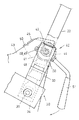
図4は、トラクタ1で例示する車両を示しており、このトラクタ1は、エンジン2、クラッチハウジング3、ミッションケース4等で車体5が構成され、この車体5の前部及び後部に左右一対の前輪6及び後輪7を備え、車体5上には、独立形成されたキャビン8が搭載されている。
キャビン8の内部には、運転席9、操縦ハンドル10、ペダル装置11等を有する操縦部12が備えられ、車体5前部に備えたエンジン2は、図3に示すように、車体5から立設した支持枠13に枢軸14を介して開閉自在に支持されたボンネット15によって覆われている。
【0009】
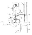
ボンネット15内において、エンジン2の吸気マニホールド20上には、これと一体に形成された支持台21を介してパワーステアリング用コントローラ22が搭載されており、前記支持台21と、前記支持枠13との間には、前後方向に長いステー23が懸架して備えられている。
そして、このステー23は、エンジン2の後部上方に設けられたマフラー24の自由端を支持するとともに、キャビン15内のアクセルペダル又はレバーの操作によって押し引き操作されるケーブル25と、エンジン2の調速レバーを操作するロッド26とを接続する中継リンク27を支持している。
【0010】
すなわち、従来においては、エンジン2等に対して直接的に又は支持部材を介してマフラー24や中継リンク27を個別に取り付けていたところ、本実施形態では、支持台21と支持枠13との間に前後に延びるステー23を設けて、中継リンク27とマフラー24とをともに支持していることから、これらの支持構造が簡素なものになり、エンジン2等に中継リンク27等を取り付けるためのネジ加工等をする必要がないようにしている。
本発明のトラクタ1においては、前記操縦ハンドル10を運転者の体格に応じて位置調整するため、又は運転席10に対する乗降性を良くするために、操縦ハンドル10を前後(上下)揺動自在とするハンドルチルト機構30が備えられている。
【0011】
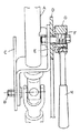
このチルト機構30は、図1及び図2に示すように、操縦ハンドル10のハンドル軸31が挿通されるハンドルポスト32の中途部に連結ブラケット33を固定し、車体5側に揺動支持板34を固定し、連結ブラケット33の下部と揺動支持板34とを左右方向の枢軸35によって連結することで、この枢軸35の軸心P回りにハンドルポスト32を前後揺動自在として構成したものとなっている。
また、ハンドル軸31は、その下端部が自在継手36及び伝動軸(図示略)を介してボンネット15内のコントローラ22に接続され、自在継手36により枢軸35と同一P軸心回りに揺動自在に備えられている。
【0012】
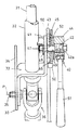
前記チルト機構30は、所望の揺動位置でハンドルポスト32の姿勢を保持するロック装置40を具備している。
このロック装置40は、ハンドルポスト32の揺動軸心P方向の面接触によって生じる摩擦抵抗でハンドルポスト32の揺動姿勢を保持するように構成しており、具体的には、連結ブラケット33から一体に上方へ突出する受板41と、車体5側に固定されていて受板41の外面に隣接するように配設された第1保持板43と、該受板41から左右外方に突出する左右方向のボルト軸42と、このボルト軸42の先端部に螺合されたホルダ44と、ホルダ44と第1保持板43との間に配設された第2保持板45と、第1、第2保持板43,45間に挟まれた状態で前記ボルト軸42に套嵌することによって前記ハンドルポスト32側に設けられた介装板46と、を有している。
【0013】
前記受板41、第1保持板43,介装板46,第2保持板45、ホルダ44は、それぞれ板面部をボルト軸42の軸心方向(左右方向)に向けた状態で隣接するものが互いに面接触し、前記第1,第2保持板43,45及び介装板46には、ボルト軸42が挿通する孔47,48,49が形成されている。
このうち、第1,第2保持板43,45に形成された孔48,49は、前記枢軸35の軸心を中心とする円弧状のガイド孔とされており、ボルト軸42は、ハンドルポスト32を前後に揺動することによってガイド孔48,49に沿って前後移動し、ガイド孔48,49の前端又は後端にボルト軸42が当接することによってハンドルポスト32の前後揺動量が規制されている。
【0014】
また、介装板46に形成された孔47は円形孔とされていて、ハンドルポスト32の揺動によって、受板41、ホルダ44とともに介装板46も揺動されるようになっている。
前記第2保持板45の前端部及び後端部には、第1保持板43側へ向けて突出するストッパー50が形成され、該ストッパー50は第1保持板43の前後側縁に係合されている。これによって、第1保持板43に対する第2保持板45の前後移動(ハンドルポスト32の揺動方向の移動)が規制されるとともに、ボルト軸42回りの回動も規制されるが、左右方向の移動は許容されるようになっている。
【0015】
前記介装板46は、ゴム材、樹脂材、繊維材(布材)等であって摩擦係数の高い材質を用いて形成されるものであるが、その材質自体の摩擦係数が高くなくとも、少なくとも第1,第2保持板43,45に対する接触面に対して高摩擦処理を施したものであってもよい。
前記ホルダ44は、円筒状に形成されるとともにその内周部に雌ネジが形成されており、ボルト軸42先端部の若干大径とされた雄ネジ42a部分に螺合されている。またホルダ44の外周には操作レバー51が取り付けられ、該操作レバー51を図2の矢印方向に揺動することによって、ホルダ44が第1、第2保持板43,45側に接近移動し、反対方向に揺動することによって第1,第2保持板43,45から離反移動するようになっている。
【0016】
また、ホルダ44の保持板45側の面には、前記介装板45と同質の摩擦係数の高い部材によって形成された摩擦板52が備えられ、実質的には、この摩擦板52が保持板45に面接触するようになっている。但し、この摩擦板52を省略してホルダ44の側面を直接的に第2保持板45に面接触させてもよい。
上記構成において、操作レバー51を揺動操作してホルダ44を第1,第2保持板43,45側へ移動するように螺進すると、ホルダ44と受板41とによって第1,第2保持板43,45及び介装板46が左右外側から挟圧され、ここに受板41及びホルダ44は、第1,第2保持板41,44を揺動軸心方向外側から挟圧する一対の挟圧体を構成している。
【0017】
この際、車体5側に固定とされてハンドルポスト32の揺動方向への移動が規制される第1保持板43と受板41との接触面、及び第1保持板43と介装板46との接触面、ハンドルポスト32の揺動方向への移動が規制された第2保持板45と介装板46との接触面、及び第2保持板45とホルダ44(実質的には摩擦板52)との接触面、には摩擦抵抗が発生し、この摩擦抵抗によってハンドルポスト32の姿勢が保持される。
すなわち、図5に示した従来技術においては、受板Eと保持板Dの間、及び保持板DとホルダGとの間の2箇所の面接触部において発生する摩擦抵抗でハンドルポストAを保持していたところ、本発明では、第2保持板45及び介装板46を付加的に設けることによって、受板41、第1保持板43、介装板46、第2保持板45、ホルダ44(摩擦板52)の各間4箇所の面接触部において発生する摩擦抵抗によりハンドルポスト32を保持できるため、その分大きな摩擦抵抗が得ることができ、操作レバー51の操作力(受板41及びホルダ44による挟圧力)を小さくしても強固にハンドルポスト32を保持できるようになる。逆に、ロック解除も小さい操作力で簡単に行えるようになる。
【0018】
また、ハンドルポスト32は、ガイド孔48,49の範囲内であればどの位置でも保持可能であるため、従来通り運転者の好みに応じた微調整も行える。
なお、第2保持板45は、第1保持板41に対する左右移動が可能であるため、介装板46がゴム材等の弾性変形可能な部材によって形成されていたとしても、その弾性変形に追従して介装板46を押圧し、両者間の摩擦抵抗及び第1保持板43と介装板46間の摩擦抵抗を確保することができるようになっている。
本発明は、上記実施形態に限ることなく適宜設計変更可能である。
【0019】
例えば、第1,第2保持板43,45の配置、又はホルダ44と受板41の配置を左右逆としてもよく、また、受板41とホルダ44との間に配設される保持板の数を3以上として各間に介装板46を設けるようにしてもよい。
受板41及びホルダ44による挟圧操作は、ネジ回動によるものに限らずカム等を利用したものであってもよく、前記ハンドルポスト32を、揺動支持板でなく第1保持板43に対して枢軸35を介して揺動自在に連結するようにしてもよい。
【0020】
車両としては、キャビンを備えないトラクタであってもよく、トラクタ以外の他の車両であってもよい。
【0021】
【発明の効果】
以上詳述したように本発明によれば、ハンドルポストの揺動姿勢の微調整を可能としながらも小さい操作力で強固に保持することができるようになる。
【図面の簡単な説明】
【図1】本発明に係るロック装置を示す正面図である。
【図2】同側面図である。
【図3】トラクタ前部の側面図である。
【図4】トラクタの全体側面図である。
【図5】従来技術に係るロック装置を示す正面図である。
【符号の説明】
1 車両
5 車体
30 チルト機構
32 ハンドルポスト
40 ロック装置
41 受板(挟圧体)
43 第1保持板
44 ホルダ(挟圧体)
45 第2保持板
46 介装板[0001]
BACKGROUND OF THE INVENTION
The present invention relates to a locking device for a tilt mechanism in a vehicle such as a tractor.
[0002]
[Prior art]
In vehicles such as tractors, the handle post of the steering handle can be swung back and forth (up and down) to adjust the position of the steering handle according to the physique of the driver and to ensure getting on and off the driver's seat The provided handle tilt mechanism is adopted.
Such a tilt mechanism is provided with a locking device so that the handle post can be held in a desired swinging posture. As a conventional locking device, for example, it is described in JP-A-6-156287. As shown in the figure, a lock lever is pivotally attached to the handle post, and a plurality of engaging portions are formed on a fixed stopper on the tractor body side, and the lock lever is selectively engaged with one of the engaging portions. By doing so, there is one configured to maintain the posture of the handle post (hereinafter, Conventional Example 1).
[0003]
Further, as shown in FIG. 5, a swing support plate C for swingably supporting the handle post A via a pivot B and a holding plate D disposed in parallel to the support post C are fixed to the tractor vehicle body side. A receiving plate E that is in surface contact with one side surface of the holding plate D is fixed to the handle post A side, and a holder G is screwed onto the tip of a bolt shaft F projecting from the receiving plate E. The holding plate D is sandwiched between the plate E and the holder G is screwed toward the holding plate D by the operation of the operation lever H, and between the holding plate D and the receiving plate E. There is also one in which the posture of the handle post A is maintained by frictional resistance (hereinafter, Conventional Example 2).
[0004]
[Problems to be solved by the invention]
In the technique of the conventional example 1, although the handle post can be firmly held by the engagement between the engagement portion and the lock lever, the tilt adjustment is performed stepwise by the plurality of engagement portions, so that it meets the driver's request. Could not be fine-tuned to the correct posture.
On the other hand, the conventional example 2 can be held at any position within the swing range of the handle post, so that fine adjustment can be made according to the driver's desire. 1 is more advantageous.
[0005]
However, in this conventional example 2, since the handle post A is held by the frictional resistance of only two surface contact portions on both surfaces of the holding plate D, the holder must be tightened to obtain a sufficient holding force. Therefore, it is necessary to operate the lever H with a large operating force, and a large amount of operating force is required for unlocking, which causes a problem of lack of operability.
SUMMARY OF THE INVENTION An object of the present invention is to provide a lock device that holds a swinging posture of a handle post by a frictional resistance so that it can be firmly held with a small operation force while allowing fine adjustment of the posture.
[0006]
[Means for Solving the Problems]
The present invention takes the following technical means to achieve the above object.
That is, the present invention relates to a tilt mechanism locking device in which the posture of the
On the
[0007]
According to this, when the
[0008]
DETAILED DESCRIPTION OF THE INVENTION
Hereinafter, embodiments of the present invention will be described with reference to the drawings.
FIG. 4 shows a vehicle exemplified by the tractor 1. The tractor 1 includes a
Inside the
[0009]
In the
The
[0010]
That is, conventionally, the
In the tractor 1 of the present invention, the
[0011]
As shown in FIGS. 1 and 2, the
The lower end portion of the
[0012]
The
The
[0013]
The
Among these, the
[0014]
Further, the
A
[0015]
The interposed
The
[0016]
Further, a
In the above configuration, when the
[0017]
At this time, the contact surface between the first holding
That is, in the prior art shown in FIG. 5, the handle post A is held by frictional resistance generated at two surface contact portions between the receiving plate E and the holding plate D and between the holding plate D and the holder G. However, in the present invention, the receiving
[0018]
Further, since the
Since the
The present invention is not limited to the above-described embodiment, and can be appropriately changed in design.
[0019]
For example, the arrangement of the first and
The clamping operation by the receiving
[0020]
The vehicle may be a tractor without a cabin, or may be a vehicle other than the tractor.
[0021]
【The invention's effect】
As described in detail above, according to the present invention, the swinging posture of the handle post can be finely adjusted, but can be firmly held with a small operating force.
[Brief description of the drawings]
FIG. 1 is a front view showing a locking device according to the present invention.
FIG. 2 is a side view of the same.
FIG. 3 is a side view of the front part of the tractor.
FIG. 4 is an overall side view of the tractor.
FIG. 5 is a front view showing a lock device according to the prior art.
[Explanation of symbols]
DESCRIPTION OF SYMBOLS 1
43
45
Claims (1)
前記車体(5)側に、前記ハンドルポスト(32)の揺動方向への移動が規制された状態で前記揺動軸心方向に並べて設けられた複数の保持板と、前記複数の保持板を前記揺動軸心方向外側から挟圧するように前記ハンドルポスト(32)側に設けられた一対の挟圧体(41,44)と、各保持板の間に挟まれた状態で前記ハンドルポスト(32)側に設けられた介装板(46)とを有し、前記複数の保持板は、車体(5)に固定され且つ、ハンドルポスト(32)に面接触する第1保持板(43)と、この第1保持板(43)に係合する第2保持板(45)とから構成され、第2保持板(45)の縁部を屈曲することにより該縁部に、第1保持板(43)の縁部に係合して該第2保持板(45)の回動を規制するストッパ(50)が形成されていることを特徴とするチルト機構のロック装置。In a locking device of a tilt mechanism in which the posture of a handle post (32) that is swingably provided on a vehicle body (5) is held by frictional resistance,
On the vehicle body (5) side, a plurality of holding plates arranged side by side in the swing axis direction in a state where movement of the handle post (32) in the swing direction is restricted, and the plurality of holding plates wherein the oscillation axis outward and the handle post as pressed between (32) a pair of clamping pressure body provided on the side (41, 44), the handle post in a state sandwiched between the holding plates ( A first holding plate (43) fixed to the vehicle body (5) and in surface contact with the handle post (32). And a second holding plate (45) that engages with the first holding plate (43). The first holding plate is attached to the edge by bending the edge of the second holding plate (45). A stopper (50) is formed which engages with the edge of (43) and regulates the rotation of the second holding plate (45). Locking device of the tilt mechanism, characterized in that is.
Priority Applications (1)
| Application Number | Priority Date | Filing Date | Title |
|---|---|---|---|
| JP30908099A JP3619086B2 (en) | 1999-10-29 | 1999-10-29 | Lock mechanism for tilt mechanism |
Applications Claiming Priority (1)
| Application Number | Priority Date | Filing Date | Title |
|---|---|---|---|
| JP30908099A JP3619086B2 (en) | 1999-10-29 | 1999-10-29 | Lock mechanism for tilt mechanism |
Publications (2)
| Publication Number | Publication Date |
|---|---|
| JP2001122130A JP2001122130A (en) | 2001-05-08 |
| JP3619086B2 true JP3619086B2 (en) | 2005-02-09 |
Family
ID=17988655
Family Applications (1)
| Application Number | Title | Priority Date | Filing Date |
|---|---|---|---|
| JP30908099A Expired - Fee Related JP3619086B2 (en) | 1999-10-29 | 1999-10-29 | Lock mechanism for tilt mechanism |
Country Status (1)
| Country | Link |
|---|---|
| JP (1) | JP3619086B2 (en) |
-
1999
- 1999-10-29 JP JP30908099A patent/JP3619086B2/en not_active Expired - Fee Related
Also Published As
| Publication number | Publication date |
|---|---|
| JP2001122130A (en) | 2001-05-08 |
Similar Documents
| Publication | Publication Date | Title |
|---|---|---|
| JPH0234145Y2 (en) | ||
| JP2019206210A (en) | Steering device and cargo handling vehicle | |
| JP3322762B2 (en) | Shift lever device for vehicles | |
| JP3619086B2 (en) | Lock mechanism for tilt mechanism | |
| JP4229524B2 (en) | Driving operation device and its mounting device | |
| JPH11278283A (en) | Automotive steering column | |
| US6036160A (en) | Rearview mirror support structure | |
| JP3906092B2 (en) | Tilt steering device | |
| JP3788004B2 (en) | Seat mounted drive robot fixing device | |
| JP2524580Y2 (en) | Work vehicle tilt handle structure | |
| JP3009739U (en) | Steering handle device for outboard motor | |
| JP4373151B2 (en) | Tractor | |
| JP2001012587A (en) | Shift lever supporting device | |
| JP2001010378A (en) | Seat for vehicle | |
| JPS6052026B2 (en) | Steering handle position adjustment device | |
| JPH0719972Y2 (en) | Motorcycle footrest support device | |
| JPH0224369Y2 (en) | ||
| JP2543430Y2 (en) | Speed change lever | |
| JPH079898A (en) | Trunk-through seat structure | |
| JP2563559Y2 (en) | Steering column support device | |
| JP2766148B2 (en) | Lock structure of tilt handle | |
| JPH0415534Y2 (en) | ||
| JP3962179B2 (en) | Opening and closing support structure of bonnet in work vehicle | |
| JPH09277890A (en) | Safety frame of working vehicle | |
| JPS6343967Y2 (en) |
Legal Events
| Date | Code | Title | Description |
|---|---|---|---|
| A977 | Report on retrieval |
Effective date: 20040616 Free format text: JAPANESE INTERMEDIATE CODE: A971007 |
|
| A131 | Notification of reasons for refusal |
Effective date: 20040803 Free format text: JAPANESE INTERMEDIATE CODE: A131 |
|
| A521 | Written amendment |
Effective date: 20041001 Free format text: JAPANESE INTERMEDIATE CODE: A523 |
|
| TRDD | Decision of grant or rejection written | ||
| A01 | Written decision to grant a patent or to grant a registration (utility model) |
Free format text: JAPANESE INTERMEDIATE CODE: A01 Effective date: 20041109 |
|
| A61 | First payment of annual fees (during grant procedure) |
Effective date: 20041111 Free format text: JAPANESE INTERMEDIATE CODE: A61 |
|
| R150 | Certificate of patent (=grant) or registration of utility model |
Free format text: JAPANESE INTERMEDIATE CODE: R150 |
|
| FPAY | Renewal fee payment (prs date is renewal date of database) |
Free format text: PAYMENT UNTIL: 20081119 Year of fee payment: 4 |
|
| FPAY | Renewal fee payment (prs date is renewal date of database) |
Free format text: PAYMENT UNTIL: 20091119 Year of fee payment: 5 |
|
| FPAY | Renewal fee payment (prs date is renewal date of database) |
Year of fee payment: 5 Free format text: PAYMENT UNTIL: 20091119 |
|
| FPAY | Renewal fee payment (prs date is renewal date of database) |
Free format text: PAYMENT UNTIL: 20101119 Year of fee payment: 6 |
|
| FPAY | Renewal fee payment (prs date is renewal date of database) |
Year of fee payment: 7 Free format text: PAYMENT UNTIL: 20111119 |
|
| LAPS | Cancellation because of no payment of annual fees |