JP3620002B2 - Case for igniter - Google Patents
Case for igniter Download PDFInfo
- Publication number
- JP3620002B2 JP3620002B2 JP23469494A JP23469494A JP3620002B2 JP 3620002 B2 JP3620002 B2 JP 3620002B2 JP 23469494 A JP23469494 A JP 23469494A JP 23469494 A JP23469494 A JP 23469494A JP 3620002 B2 JP3620002 B2 JP 3620002B2
- Authority
- JP
- Japan
- Prior art keywords
- case
- transformer
- main body
- body case
- filler
- Prior art date
- Legal status (The legal status is an assumption and is not a legal conclusion. Google has not performed a legal analysis and makes no representation as to the accuracy of the status listed.)
- Expired - Lifetime
Links
- 239000000945 filler Substances 0.000 claims description 21
- 238000005192 partition Methods 0.000 claims description 14
- 239000002184 metal Substances 0.000 claims description 10
- 229910052751 metal Inorganic materials 0.000 claims description 10
- 238000002485 combustion reaction Methods 0.000 description 3
- 238000010892 electric spark Methods 0.000 description 3
- 229910052774 Proactinium Inorganic materials 0.000 description 2
- 238000010586 diagram Methods 0.000 description 2
- 239000000428 dust Substances 0.000 description 2
- 230000000694 effects Effects 0.000 description 2
- 239000003822 epoxy resin Substances 0.000 description 2
- 238000009413 insulation Methods 0.000 description 2
- 229910052745 lead Inorganic materials 0.000 description 2
- WABPQHHGFIMREM-UHFFFAOYSA-N lead(0) Chemical compound [Pb] WABPQHHGFIMREM-UHFFFAOYSA-N 0.000 description 2
- 239000000463 material Substances 0.000 description 2
- 239000004033 plastic Substances 0.000 description 2
- 229920003023 plastic Polymers 0.000 description 2
- 229920000647 polyepoxide Polymers 0.000 description 2
- 238000005452 bending Methods 0.000 description 1
- 230000006866 deterioration Effects 0.000 description 1
- 238000005516 engineering process Methods 0.000 description 1
- 238000007689 inspection Methods 0.000 description 1
- 238000000034 method Methods 0.000 description 1
- 229920002803 thermoplastic polyurethane Polymers 0.000 description 1
Images


Landscapes
- Housings And Mounting Of Transformers (AREA)
Description
【0001】
【産業上の利用分野】
この発明は、電気火花によりガス燃焼器具や石油燃焼器具を点火するイグナイタを収納するためのイグナイタ用のケースに関する。
【0002】
【従来の技術】
ガス燃焼器具や石油燃焼器具には、電気火花を利用して点火する電気式のイグナイタが多用されている。
【0003】
このものは、自走マルチバイブレータ方式等により大エネルギの振動電流を発生するプリント基板と、プリント基板からの振動電流を一次側に通電し、二次側に数10kVの高電圧を出力する昇圧トランスとを組み合わせてなる。なお、昇圧トランスによって発生する高電圧は、出力リード線を介して燃焼部の近傍に配設する針電極に導き、点火用の電気火花を発生させる。
【0004】
従来のイグナイタは、プリント基板と昇圧トランスとを一体のケースに収納し、内部にエポキシ樹脂等の充填剤を充填して構成するのが普通である。充填剤は、充電部分を封止し、塵埃や湿気による絶縁劣化を有効に防止することができるからである。
【0005】
【発明が解決しようとする課題】
かかる従来技術によるときは、プリント基板と昇圧トランスとの双方を単一のケースに収納するので、ケースが大形になり、充填剤の充填量が不当に多くなる上、多数のオプション仕様に対して適確に対応させることが困難であるという問題があった。すなわち、イグナイタは、高電圧出力の電圧値やエネルギ量等の電気的仕様の他に、出力リード線の極数や位置等の機械的仕様により、多様なオプション仕様が要求されるが、これらのオプションは、共通のプリント基板に対し、所定の昇圧トランスを組み合わせることによって実現することができる。しかるに、プリント基板と昇圧トランスとを一体のケースに収納すると、そのときのケースは、オプション仕様ごとに異ならせるか、すべてのオプションに共通する大きなものとせざるを得ないからである。
【0006】
また、このように体積が大きなケースは、充填剤を充填するに際し、硬化時間が長くなり、極めて取り扱い難いという問題もあった。
【0007】
そこで、この発明の目的は、プリント基板を収納する本体ケースと、昇圧トランスを収納するトランスケースとを別体にし、両者を組み合わせることによって、多様なオプション仕様に対して簡単に対応することができる上、取扱いも極めて容易なイグナイタ用のケースを提供することにある。
【0008】
【課題を解決するための手段】
かかる目的を達成するためのこの発明の構成は、プリント基板を下向きに収納し、他の側面壁より低い仕切壁を後部に有する箱状の本体ケースと、本体ケースの後部に連結し、昇圧トランスを収納して充填剤を充填する前部開放のトランスケースとを備えてなり、本体ケースには、プリント基板上から充填剤を充填するとともに、トランスケース内の充填剤と仕切壁との間の空間にも併せて充填することをその要旨とする。
【0009】
なお、本体ケースの底壁には、エア抜き孔を設けることができる。
【0010】
また、本体ケースには、取付脚を形成してもよい。
【0011】
さらに、取付脚の少なくとも一方は、接地金具を取付可能としてもよい。
【0012】
【作用】
かかる発明の構成によるときは、トランスケースは、内部に収納する昇圧トランスに適合するものを選択し、本体ケースに組み合わせることができるから、全体として、任意のオプション仕様に対し、簡単に対応させることが可能である。
【0013】
トランスケースに充填する充填剤は、昇圧トランスに要求される絶縁性能を容易に実現することができ、本体ケースに充填する充填剤は、プリント基板を外気から遮断し、塵埃の付着等による性能劣化を有効に防止することができる。
【0014】
本体ケースの後部に設ける低い仕切壁は、トランスケースを連結した後、本体ケースに充填剤を充填することにより、仕切壁を越えて本体ケースから溢れた充填剤をトランスケースに円滑に流入させることができ、本体ケースとトランスケースとの一体性を一層高めることが可能である。なお、本体ケース、トランスケースに充填する充填剤は、エポキシ樹脂やウレタン樹脂等を使用することができる。
【0015】
本体ケースに取付脚を形成すれば、取付脚を利用して全体を任意の取付箇所に固定することができ、取付脚に接地金具を取り付けることにより、全体の電気的な接地を簡単にとることができる。
【0016】
【実施例】
以下、図面を以って実施例を説明する。
【0017】
イグナイタ用のケースは、本体ケース10とトランスケース20とを組み合わせてなる(図1)。
【0018】
本体ケース10は、プリント基板Pを収納する有底の箱状の容器体であり(図1、図2)、適当な絶縁性の硬質プラスチック材料によって一体成形されている。本体ケース10は、底壁11と、前面壁12と、左右の側面壁13、13と、後部の仕切壁14とを有している。前面壁12には、段部12a、12bが2段に形成されており、低い段部12bの中央部には、リブ12cが立設されている。また、後部の仕切壁14は、左右の側面壁13、13、前面壁12よりも低くなっており、仕切壁14、各側面壁13の上部には、プリント基板Pを設置するために、段部12bの上面と同一高さの段部14a、13aが形成されている。また、後部の仕切壁14の上端には、プリント基板Pを装着する際にガイドとなる突部14b、14bが突設されており、突部14b、14bの内側面は、斜面に形成されている。
【0019】
なお、プリント基板Pは、表面側の電子部品P1 、P1 …が下側となり、裏面側のパターン面が上側となるように本体ケース10に下向きに収納するものとし、このとき、プリント基板Pの入力端子Pa 、Pa は、段部12bに形成するスリットを介し、段部12b上にリブ12cの両側に突出するものとする。また、本体ケース10の後部には、左右に取付脚15、16が突設されており、一方の取付脚15には、取付用の丸孔15aの他に、接地金具17を挿通するためのスリット15bが形成されており(図1、図3)、他方の取付脚16には、外側に向けて開口する取付用の長孔16aが形成されている。ただし、スリット15bは、一端をプリント基板Pにはんだ付けする舌片状の接地金具17を屈曲して装着するために使用する(図3)。接地金具17の他端部には、丸孔15aに対応して取付孔17aが形成されており、接地金具17は、取付脚15の表面に沿って延長されている。
【0020】
底壁11、側面壁13、13の後端部内面には、仕切壁14の外面に沿って嵌合溝11a、13a、13a、嵌合リブ11b、13b、13bが平行に形成されている(図1、図4)。また、底壁11の一部には、深い凹所11cが形成されており(図2)、凹所11cは、図示しない微少径のエア抜き孔を介し、底壁11を貫通しているものとする。
【0021】
トランスケース20は、昇圧トランスTを収納する前面開放の容器体である(図1、図2)。昇圧トランスTには、屈曲ピンからなる一次側端子Ta 、Ta …が付属しており、一次側端子Ta 、Ta …は、トランスケース20の前面の開放部に下向きに突出されている。
【0022】
トランスケース20は、絶縁性の硬質プラスチック材料によって一体成形されている。トランスケース20は、底壁21、左右の側面壁22、22、上壁23を有し、後部は、昇圧トランスTの外形に適合する異形に形成されている。トランスケース20の後部両側には、筒状の高圧出力部24、24が突設形成されており、直線ピンからなる昇圧トランスTの出力端子Tb 、Tb は、それぞれ、対応する高圧出力部24の内部に突き出されている。そこで、図示しない出力リード線は、高圧出力部24、24に挿し込むことにより、出力端子Tb 、Tb に接続することができる。
【0023】
底壁21、左右の側面壁22、22の前端部外面には、嵌合溝21a、22a、22a、嵌合リブ21b、22b、22bが平行に形成されている(図1、図4)。ただし、嵌合リブ21b、22b、22bは、それぞれ、本体ケース10側の嵌合溝11a、13a、13aに適合し、嵌合溝21a、22a、22aは、それぞれ、本体ケース10側の嵌合リブ11b、13b、13bに適合するものとする。
【0024】
そこで、トランスケース20は、嵌合リブ22b、22bを嵌合溝13a、13aに対応させ、嵌合溝22a、22aを嵌合リブ13b、13bに対応させることにより、本体ケース10に対し、上方からスライド嵌合させるようにして一体に連結することができる(図2、図4)。なお、このとき、連結の最終段階において、嵌合リブ21b、11bは、それぞれ嵌合溝11a、21aに嵌合し、トランスケース20、本体ケース10の連結を完成することができる。また、昇圧トランスTの一次側端子Ta 、Ta …は、プリント基板Pの出力用の鳩目Pb 、Pb …に先端部が挿入され(図1、図2)、鳩目Pb 、Pb …の部分においてはんだ付けすることにより、プリント基板Pと昇圧トランスTとを電気的に接続することができる。
【0025】
かかる本体ケース10、トランスケース20は、それぞれを個別に完成させた後、両者を連結する。すなわち、本体ケース10は、プリント基板Pを収納するとともに、一方の取付脚15のスリット15bを介して接地金具17を取り付け、プリント基板Pに一端をはんだ付けしておく。一方、トランスケース20は、昇圧トランスTを収納した上、前面の開放部を上にし、後部の高圧出力部24、24を下にして、ほぼ一杯になるまで充填剤EXを充填する(図2)。なお、このとき、昇圧トランスTは、そのボビンT1 の端面にリブT1aを形成し、リブT1aを側面壁22の内面に形成する位置決め用のリブ22c、22cに係合させることにより、トランスケース20内に安定に収納することができる。
【0026】
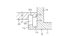
トランスケース20内の充填剤EXが十分に硬化したら、トランスケース20を本体ケース10に連結し、昇圧トランスTの一次側端子Ta 、Ta …をプリント基板Pの鳩目Pb 、Pb …にはんだ付けする。これにより、プリント基板Pと昇圧トランスTとの電気的接続を完了することができるから、つづいて、プリント基板P上から本体ケース10内に充填剤UXを充填する。このとき、本体ケース10の底壁11にはエア抜き孔があるので、充填剤UXは、プリント基板Pの下部の空間をも満たすことができる上、一部は、低い仕切壁14を越えてトランスケース20内に流入し、充填剤EXの表面と仕切壁14との間の空間にも充填することができる(図2)。
【0027】
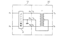
充填剤UXが硬化したら、所定の検査工程を経て完成品とする。なお、このものは、取付脚15、16を利用して任意の取付箇所に固定することができ、このとき、取付脚15側の取付ねじを利用して接地金具17を共締めすることにより、安定な接地をとることが可能である。また、全体の電気系統は、たとえば図5のとおりである。
【0028】
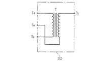
以上の説明において、出力リード線が2極でなく、1極のみでよい場合(図6)、トランスケース20は、図1において、右側または左側の一方の高圧出力部24のみを設ければよい。なお、このときの高圧出力部24の位置は、右側または左側に指定される場合もある。そこで、かかるオプション仕様に対応するために、昇圧トランスT、トランスケース20は、本体ケース10との関係寸法を一定にして数種類を用意し、オプション仕様に応じて昇圧トランスT、トランスケース20を選択した上、本体ケース10と組み合わせることができる。すなわち、トランスケース20は、オプション仕様に従い、本体ケース10に対して交換自在に組み合わせるものとする。
【0029】
また、取付脚15、16は、両者を同一形状にしてもよく、このとき、接地金具17は、両者に取付可能にしてもよい。
【0030】
【発明の効果】
以上説明したように、この発明によれば、本体ケースと、本体ケースの後部に連結するトランスケースとを組み合わせることによって、多くのオプション仕様は、昇圧トランスを収納するトランスケースを選択し、本体ケースに組み合わせて実現することができるから、多様なオプション仕様に対して簡単に対応することができる上、本体ケース、トランスケースは、両者が別体であるから、個別に容易に取り扱うことができるという優れた効果がある。
【図面の簡単な説明】
【図1】全体分解斜視図
【図2】図1の縦断面相当説明図
【図3】図1のX−X線矢視相当拡大断面図
【図4】図2の要部拡大説明図
【図5】電気系統図
【図6】要部電気系統図
【符号の説明】
P…プリント基板
T…昇圧トランス
EX、UX…充填剤
10…本体ケース
13…側面壁
14…仕切壁
15、16…取付脚
17…接地金具
20…トランスケース[0001]
[Industrial application fields]
The present invention relates to a case for an igniter for housing an igniter for igniting a gas combustion apparatus or an oil combustion apparatus with an electric spark.
[0002]
[Prior art]
An electric igniter that uses an electric spark to ignite is often used in gas burning equipment and oil burning equipment.
[0003]
This includes a printed circuit board that generates a large energy oscillating current by a self-running multivibrator system, etc., and a step-up transformer that supplies the oscillating current from the printed circuit board to the primary side and outputs a high voltage of several tens of kV to the secondary side. And in combination. Note that the high voltage generated by the step-up transformer is guided to a needle electrode disposed in the vicinity of the combustion portion via an output lead wire to generate an electric spark for ignition.
[0004]
Conventional igniters are usually configured by housing a printed circuit board and a step-up transformer in an integrated case and filling a filler such as an epoxy resin inside. This is because the filler seals the charged part and can effectively prevent insulation deterioration due to dust and moisture.
[0005]
[Problems to be solved by the invention]
According to such a conventional technology, since both the printed circuit board and the step-up transformer are accommodated in a single case, the case becomes large, the amount of filler filling is unreasonably large, and for a number of optional specifications. There is a problem that it is difficult to respond appropriately. In other words, the igniter is required to have various optional specifications depending on the mechanical specifications such as the number and position of the output lead wires in addition to the electrical specifications such as the voltage value and energy amount of the high voltage output. The option can be realized by combining a predetermined step-up transformer with a common printed circuit board. However, if the printed circuit board and the step-up transformer are housed in an integrated case, the case at that time must be made different for each option specification or large for all options.
[0006]
In addition, the case with such a large volume has a problem that it takes a long time to cure and is extremely difficult to handle.
[0007]
Therefore, an object of the present invention is to easily cope with various option specifications by separating the main body case for storing the printed circuit board and the transformer case for storing the step-up transformer, and combining them. Another object is to provide an igniter case that is extremely easy to handle.
[0008]
[Means for Solving the Problems]
In order to achieve such an object, the structure of the present invention includes a box-shaped main body case that houses a printed circuit board downward, has a partition wall lower than other side walls at the rear, and a rear portion of the main body case. A main body case is filled with the filler from above the printed circuit board, and between the filler in the transformer case and the partition wall. The gist is to fill the space together.
[0009]
An air vent hole can be provided in the bottom wall of the main body case.
[0010]
Moreover, you may form an attachment leg in a main body case.
[0011]
Furthermore, at least one of the attachment legs may be capable of attaching a grounding metal fitting.
[0012]
[Action]
According to the configuration of the present invention, the transformer case can be selected to be suitable for the step-up transformer housed inside and can be combined with the main body case, so that it can be easily adapted to any optional specifications as a whole. Is possible.
[0013]
The filler filled in the transformer case can easily achieve the insulation performance required for the step-up transformer, and the filler filled in the body case blocks the printed circuit board from the outside air and deteriorates performance due to dust adhesion etc. Can be effectively prevented.
[0014]
The low partition wall provided at the rear of the main body case allows the filler overflowing from the main body case to flow smoothly into the transformer case beyond the partition wall by filling the main body case with the filler after connecting the transformer case. It is possible to further enhance the unity between the main body case and the transformer case. In addition, an epoxy resin, a urethane resin, etc. can be used for the filler with which a main body case and a transformer case are filled.
[0015]
If the mounting legs are formed on the main body case, the whole can be fixed to any mounting location using the mounting legs, and the entire electrical grounding can be easily taken by attaching a grounding bracket to the mounting legs. Can do.
[0016]
【Example】
Hereinafter, embodiments will be described with reference to the drawings.
[0017]
The igniter case is a combination of the
[0018]
The
[0019]
The printed circuit board P is stored downward in the
[0020]
Fitting
[0021]
The
[0022]
The
[0023]
Fitting
[0024]
Therefore, the
[0025]
After the
[0026]
When the filler EX in the
[0027]
When the filler UX is cured, a finished product is obtained through a predetermined inspection process. In addition, this thing can be fixed to arbitrary attachment locations using the
[0028]
In the above description, when the output lead wire has only one pole instead of two poles (FIG. 6), the
[0029]
Further, the mounting
[0030]
【The invention's effect】
As described above, according to the present invention, by combining the main body case and the transformer case connected to the rear portion of the main body case, many optional specifications select the transformer case that houses the step-up transformer, and the main body case Because it can be realized in combination, it can easily cope with various optional specifications, and since the main body case and the transformer case are separate, they can be easily handled individually. Has an excellent effect.
[Brief description of the drawings]
1 is an overall exploded perspective view. FIG. 2 is an explanatory view corresponding to a vertical cross section of FIG. 1. FIG. 3 is an enlarged cross sectional view corresponding to an arrow XX in FIG. Fig. 5 Electrical system diagram [Fig. 6] Main system electrical diagram [Explanation of symbols]
P ... Printed circuit board T ... Booster transformer EX, UX ...
Claims (4)
Priority Applications (1)
| Application Number | Priority Date | Filing Date | Title |
|---|---|---|---|
| JP23469494A JP3620002B2 (en) | 1994-09-29 | 1994-09-29 | Case for igniter |
Applications Claiming Priority (1)
| Application Number | Priority Date | Filing Date | Title |
|---|---|---|---|
| JP23469494A JP3620002B2 (en) | 1994-09-29 | 1994-09-29 | Case for igniter |
Publications (2)
| Publication Number | Publication Date |
|---|---|
| JPH0897058A JPH0897058A (en) | 1996-04-12 |
| JP3620002B2 true JP3620002B2 (en) | 2005-02-16 |
Family
ID=16974957
Family Applications (1)
| Application Number | Title | Priority Date | Filing Date |
|---|---|---|---|
| JP23469494A Expired - Lifetime JP3620002B2 (en) | 1994-09-29 | 1994-09-29 | Case for igniter |
Country Status (1)
| Country | Link |
|---|---|
| JP (1) | JP3620002B2 (en) |
Families Citing this family (4)
| Publication number | Priority date | Publication date | Assignee | Title |
|---|---|---|---|---|
| IT1303090B1 (en) * | 1998-07-28 | 2000-10-30 | Miller Europe Spa | ELECTRONIC GAS LIGHTER INTEGRATED WITH A TERMINAL BOARD. |
| IT1303088B1 (en) * | 1998-07-28 | 2000-10-30 | Miller Europe Spa | QUICK-CONNECT ELECTRONIC GAS LIGHTER DEVICE. |
| JP4501673B2 (en) * | 2004-12-16 | 2010-07-14 | 株式会社デンソー | Ignition coil |
| DE102009009033B4 (en) * | 2009-02-16 | 2020-11-12 | SUMIDA Components & Modules GmbH | Housing for an ignition transformer, transformer device and electronic ballast for a gas discharge lamp |
-
1994
- 1994-09-29 JP JP23469494A patent/JP3620002B2/en not_active Expired - Lifetime
Also Published As
| Publication number | Publication date |
|---|---|
| JPH0897058A (en) | 1996-04-12 |
Similar Documents
| Publication | Publication Date | Title |
|---|---|---|
| KR101055040B1 (en) | Ion Generator and Electric Appliance | |
| US9362881B2 (en) | Noise filter device | |
| US5959521A (en) | High-voltage transformer and a vehicle-lamp lighting-on device using the same | |
| EP0902605A1 (en) | Discharge lamp lighting device | |
| JP4541387B2 (en) | Socket for discharge lamp | |
| JP3620002B2 (en) | Case for igniter | |
| JP4689698B2 (en) | Ion generator | |
| JP3129531U (en) | Negative ion generator with voltage stabilizer for vehicles | |
| JP3598857B2 (en) | Discharge lamp lighting device | |
| JP3445830B2 (en) | High voltage generator for two ports | |
| CN108630417B (en) | Ignition coil for internal combustion engine | |
| JP3867488B2 (en) | Lamp socket | |
| EP1135010A2 (en) | Starting device for discharge lamp | |
| JP4668294B2 (en) | Ion generator and electrical equipment | |
| JP3121595B1 (en) | Socket and discharge lamp lighting device | |
| JPH0512618Y2 (en) | ||
| CN109983297A (en) | The igniter assembly and its manufacturing method of gas generator | |
| JP2013182796A (en) | Lighting device for discharge lamp, and manufacturing method thereof | |
| JPS6345837Y2 (en) | ||
| JPS6143088Y2 (en) | ||
| JPH0680298U (en) | High pressure discharge lamp lighting device | |
| JP4575661B2 (en) | High voltage pulse generator | |
| JP2001015358A (en) | Step-up transformer device for ignition device | |
| JP4547834B2 (en) | High voltage pulse generator | |
| JPH075298U (en) | High pressure discharge lamp lighting device |
Legal Events
| Date | Code | Title | Description |
|---|---|---|---|
| A977 | Report on retrieval |
Free format text: JAPANESE INTERMEDIATE CODE: A971007 Effective date: 20040714 |
|
| A131 | Notification of reasons for refusal |
Free format text: JAPANESE INTERMEDIATE CODE: A131 Effective date: 20040727 |
|
| A521 | Written amendment |
Free format text: JAPANESE INTERMEDIATE CODE: A523 Effective date: 20040917 |
|
| TRDD | Decision of grant or rejection written | ||
| A521 | Written amendment |
Free format text: JAPANESE INTERMEDIATE CODE: A821 Effective date: 20040917 |
|
| A01 | Written decision to grant a patent or to grant a registration (utility model) |
Free format text: JAPANESE INTERMEDIATE CODE: A01 Effective date: 20041026 |
|
| A61 | First payment of annual fees (during grant procedure) |
Free format text: JAPANESE INTERMEDIATE CODE: A61 Effective date: 20041105 |
|
| R150 | Certificate of patent (=grant) or registration of utility model |
Free format text: JAPANESE INTERMEDIATE CODE: R150 |
|
| FPAY | Renewal fee payment (prs date is renewal date of database) |
Free format text: PAYMENT UNTIL: 20081126 Year of fee payment: 4 |
|
| FPAY | Renewal fee payment (prs date is renewal date of database) |
Free format text: PAYMENT UNTIL: 20091126 Year of fee payment: 5 |
|
| FPAY | Renewal fee payment (prs date is renewal date of database) |
Free format text: PAYMENT UNTIL: 20101126 Year of fee payment: 6 |
|
| FPAY | Renewal fee payment (prs date is renewal date of database) |
Free format text: PAYMENT UNTIL: 20101126 Year of fee payment: 6 |
|
| FPAY | Renewal fee payment (prs date is renewal date of database) |
Free format text: PAYMENT UNTIL: 20111126 Year of fee payment: 7 |
|
| FPAY | Renewal fee payment (prs date is renewal date of database) |
Free format text: PAYMENT UNTIL: 20111126 Year of fee payment: 7 |
|
| FPAY | Renewal fee payment (prs date is renewal date of database) |
Free format text: PAYMENT UNTIL: 20141126 Year of fee payment: 10 |
|
| EXPY | Cancellation because of completion of term |