JP3620004B2 - Envelope - Google Patents
Envelope Download PDFInfo
- Publication number
- JP3620004B2 JP3620004B2 JP32216595A JP32216595A JP3620004B2 JP 3620004 B2 JP3620004 B2 JP 3620004B2 JP 32216595 A JP32216595 A JP 32216595A JP 32216595 A JP32216595 A JP 32216595A JP 3620004 B2 JP3620004 B2 JP 3620004B2
- Authority
- JP
- Japan
- Prior art keywords
- plate
- end receiving
- tight frame
- surrounding
- plate end
- Prior art date
- Legal status (The legal status is an assumption and is not a legal conclusion. Google has not performed a legal analysis and makes no representation as to the accuracy of the status listed.)
- Expired - Fee Related
Links
- 230000000630 rising effect Effects 0.000 description 10
- 229910000831 Steel Inorganic materials 0.000 description 6
- 239000010959 steel Substances 0.000 description 6
- 230000000694 effects Effects 0.000 description 2
- 238000003466 welding Methods 0.000 description 2
- 238000005452 bending Methods 0.000 description 1
- 239000002184 metal Substances 0.000 description 1
Images


Landscapes
- Roof Covering Using Slabs Or Stiff Sheets (AREA)
- Finishing Walls (AREA)
Description
【0001】
【発明の属する技術分野】
本発明は天井兼屋根として或は外壁として使用される外囲体に関する。
【0002】
【従来の技術】
図7に示すように、H型鋼或はI型鋼から成る梁2にタイトフレーム4を溶接によって固定し、このタイトフレーム4に波型の折り板6をボルト8によって固定し、天井兼屋根として使用される外囲体を構成することが従来知られている。
【0003】
【発明が解決しようとする課題】
上記従来の外囲体は、折り板の両側及び中央をボルトによってタイトフレームに固定しているため、折り板のタイトフレームに対する結合作業が容易でなく、しかも、折り板が熱によって膨張すると、この膨張を逃げることができないので、折り板がたわんでしまうという問題点が存した。
本発明は上記問題点を解決することを目的とするものである。
【0004】
【課題を解決するための手段】
上記目的を達成するため、本発明は、梁(2)にタイトフレーム(10)を固定し、該タイトフレーム(10)に複数の外囲板(12)を結合するようにした外囲体において、前記タイトフレーム(10)の主フレーム部(10a)の両側に所定間隔を存して凸面部(10b)(10c)と、該凸面部(10b)(10c)に隣接する板端受部(10g)(10h)を設け、前記各外囲板(12)の主平板部(12a)の一側部にL型に屈折した板端受部(12e)とこれに隣接して横V字状の第1の引掛部(12f)を設け、前記各外囲板(12)の主平板部(12a)の他側部にV字状の第2の引掛部(12h)を設け、前記各外囲板(12)の一側部の第1の引掛部(12f)を前記タイトフレーム(10)の一方の板端受部(10g)に嵌合し、前記各外囲板(12)の他側部の第2の引掛部(12h)を隣接する外囲板(12)の一側部の板端受部(12e)に嵌合したものである。
【0005】
【発明の実施の形態】
以下に本発明の好適な実施の形態を添付図面を参照して詳細に説明する。
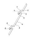
2は建物の屋根や外壁を支える梁であり、H型鋼或はI型鋼が使用されている。10は帯状の鋼板などから成るタイトフレームであり、前記梁2の上位水平部2aの上面に溶接或は、ボルトによって固定されている。前記タイトフレーム10は、図3に示すように、帯状の主フレーム部10aの両端に横コ字状の凸面部10b,10cが屈折形成されている。
【0006】
前記凸面部10b,10cは主フレーム部10aに対して垂直な立ち上り部10d,10eと、主フレーム部10aに対して水平な支持面部10fとから構成されている。前記各凸面部10b,10cの一側には、L字状の板端受部10g,10hが屈折形成されている。前記板端受部10g,10hは、垂直部とこれに対して直角な水平部とから構成され、各水平部は、隣接する凸面部10b,10cとは反対方向に向いている。前記タイトフレーム10は、一つの梁2上に複数、梁2の長手方向の同軸線上に直列に配置されている。
【0007】
タイトフレーム10の凸面部10b,10cの間隔Sと、隣接する2つのタイトフレーム10,10の互いに対向する凸面部10b,10cの間隔S’は同一に設定されている。前記梁2は、互いに平行に複数配置され、各梁2上のタイトフレーム10は、梁2の長手方向に対して直角な同軸線上で一致するように配置されている。12は鋼板などの長尺状の金属板から成る外囲板であり、図1中、紙面垂直方向を長手方向としている。前記外囲板12の主平板部12aの両側には、立ち上り部12b,12cが形成され、外囲板12の中央部の断面形状が横コ字状に構成されている。
【0008】
前記主平板部12aは、前記タイトフレーム10の主フレーム部10aに適合している。前記一対の立ち上り部12b,12cのうち、一方の立ち上り部12bの側部には下向きに凹んだ横コ字状の凹入部12dが形成されている。前記凹入部12dの底部の略中央には、L型状の板端受部12eが外囲板12の全長にわたって屈折形成されている。前記板端受部12eの上位水平部は前記主平板部12aの方向に突出している。前記凹入部12dの外側には、前記タイトフレーム10の板端受部10gに適合する横V字状の引掛部12fが形成されている。
【0009】
前記一対の立ち上り部12b,12cのうち、他方の立ち上り部12cの側部には帯状の水平な側板部12gが形成され、該側板部12gの側縁部には前記板端受部12eに適合する、断面形状がV字状の引掛部12hが屈折形成されている。前記引掛部12f水平部、板端受部12eの上位水平部、側板部12gは、同一平面上に形成されている。前記外囲板12は同一形状のものが複数用意されている。各外囲板12の主平板部12aは、図1中、紙面に垂直な同一軸線上の対応する各タイトフレーム10の主フレーム部10aに載置され、一方の引掛部12fが、対応する各タイトフレーム10の板端受部10gに図1中、紙面垂直方向にスライド自在に係合される。
【0010】
該係合状態において、引掛部12fの横の凹入部12dはその底部が対応する各タイトフレーム10の凸面部10bに載置される。外囲板12の他方の引掛部12hは、隣接する外囲板12の板端受部12eに図1中、紙面垂直方向にスライド自在に係合される。このようにして、梁2上に並列状に展開配置された複数の外囲板12は、一方がタイトフレーム10の一方の板端受部10gに係合し、他方が、隣接する外囲板12の板端受部12eを介して、タイトフレーム10の他方の板端受部10hに係合し、しっかりと、梁2に結合される。
【0011】
上記した構成において、外囲板12が熱膨張によって、長手方向及び直角方向に伸縮すると、外囲板12は、タイトフレーム10及び隣接する外囲板12に対してスライドし、これによって外囲板12にたわみが生じることがない。
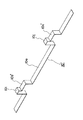
次に本発明の他の実施の形態を図4乃至6を参照して説明する。
10’は梁2に固定されたタイトフレームであり、凸面部10b’,10c’の横に、該凸面部10b’,10c’より一段高い凸面状の板端受部10i,10jが形成されている。タイトフレーム10’の他の構成は、図3に示すタイトフレーム10と同一である。
【0012】
12’は外囲板であり、一側部の側板部12iには図2に示す横V字状の引掛部12fが形成されていない。この引掛部12fが無い点を除いては、図5に示す外囲板12’の構成は、図2に示す外囲板12の構成と同一である。この外囲板12’の、図2に示す外囲板12と同一構成部分には同一の符号を付して、対応関係を明らかにしてある。複数の同一形状の外囲板12’の主平板部12aは、図4中、紙面に垂直な同一軸線上の対応する各タイトフレーム10’の主フレーム部10aに載置され、一方の側板部12iが、対応する各タイトフレーム10’の板端受部10iにビス14によって固定される。
【0013】
該固定状態において、側板部12iの横の凹入部12dは、その底部が対応する各タイトフレーム10’の凸面部10b’に載置される。外囲板12’の他方の引掛部12hは隣接する外囲板12’の板端受部12eに図4中、紙面垂直方向にスライド自在に係合される。このようにして、梁2上に並列状に展開配置された複数の外囲板12は、一方がタイトフレーム10’の一方の板端受部10iにビス止め固定され、他方が、隣接する外囲板12の板端受部12eを介して、タイトフレーム10’の他方の板端受部10jに係合し、しっかりと各外囲板12’は、タイトフレーム10’を介して梁2に結合される。
【0014】
上記した構成において、外囲板12’が熱膨張によって長手方向及び直角方向に伸縮しても、外囲板12’は、一側のみがタイトフレーム10’にビス止めされ、他側部は非固定状態なので、外囲板12’の他側部の、タイトフレーム10’及び隣接する外囲板12’に対するスライドによって、外囲板12’の熱膨張によるたわみが少なくなる。
【0015】
【効果】
本発明は上述の如く構成したので、外囲板の梁に対する取り付けを容易に行うことができるとともに、外囲板の熱膨張による変形を防止或は少なくすることができる等の効果が存する。
【図面の簡単な説明】
【図1】本発明の好適な実施の形態を示す断面図である。
【図2】外囲板の外観図である。
【図3】タイトフレームの外観図である。
【図4】本発明の他の実施の形態を示す断面図である。
【図5】外囲体の他の実施の形態を示す外観図である。
【図6】タイトフレームの他の実施の形態を示す外観図である。
【図7】従来技術の外観図である。
【符号の説明】
2 梁
4 タイトフレーム
6 折り板
8 ボルト
10 タイトフレーム
10’ タイトフレーム
10a 主フレーム部
10b 凸面部
10c 凸面部
10d 立ち上り部
10e 立ち上り部
10f 支持面部
10g 板端受部
10h 板端受部
10i 板端受部
10j 板端受部
12 外囲板
12’ 外囲板
12a 主平板部
12b 立ち上り部
12c 立ち上り部
12d 凹入部
12e 板端受部
12f 引掛部
12g 側板部
12h 引掛部
12i 側板部
14 ビス[0001]
BACKGROUND OF THE INVENTION
The present invention relates to an enclosure used as a ceiling and roof or as an outer wall.
[0002]
[Prior art]
As shown in FIG. 7, a tight frame 4 is fixed to a
[0003]
[Problems to be solved by the invention]
In the above-described conventional envelope, both sides and the center of the folded plate are fixed to the tight frame with bolts. Therefore, it is not easy to join the folded plate to the tight frame, and when the folded plate expands due to heat, There was a problem that the folded plate would bend because it could not escape the expansion.
The present invention aims to solve the above problems.
[0004]
[Means for Solving the Problems]
In order to achieve the above object, the present invention provides an envelope in which a tight frame (10) is fixed to a beam (2) and a plurality of envelope plates (12) are coupled to the tight frame (10). The convex surface portions (10b) and (10c) and the plate end receiving portions (10c) adjacent to the convex surface portions (10b) and (10c) at predetermined intervals on both sides of the main frame portion (10a) of the tight frame (10). 10g) (10h) is provided, and a plate end receiving portion (12e) refracted in an L shape on one side of the main flat plate portion (12a) of each of the surrounding plates (12) and a horizontal V-shape adjacent thereto The first hooking portion (12f) is provided, and a V-shaped second hooking portion (12h) is provided on the other side of the main flat plate portion (12a) of each outer envelope plate (12). The first hooking portion (12f) on one side of the surrounding plate (12) is connected to one plate end receiving portion (10g) of the tight frame (10). And the second hooking portion (12h) on the other side of each of the surrounding plates (12) is fitted to the plate end receiving portion (12e) on one side of the adjacent surrounding plate (12). It is a thing.
[0005]
DETAILED DESCRIPTION OF THE INVENTION
Preferred embodiments of the present invention will be described below in detail with reference to the accompanying drawings.
[0006]
The
[0007]
The interval S between the
[0008]
The main
[0009]
Of the pair of rising
[0010]
In the engaged state, the horizontal recessed
[0011]
In the above-described configuration, when the surrounding
Next, another embodiment of the present invention will be described with reference to FIGS.
10 'is a tight frame fixed to the
[0012]
Reference numeral 12 'denotes an envelope plate, and the side plate portion 12i on one side portion is not formed with the lateral V-
[0013]
In the fixed state, the lateral recessed
[0014]
In the above-described configuration, even if the surrounding
[0015]
【effect】
Since the present invention is configured as described above, there are effects such that the outer plate can be easily attached to the beam, and deformation due to thermal expansion of the outer plate can be prevented or reduced.
[Brief description of the drawings]
FIG. 1 is a cross-sectional view showing a preferred embodiment of the present invention.
FIG. 2 is an external view of an envelope plate.
FIG. 3 is an external view of a tight frame.
FIG. 4 is a cross-sectional view showing another embodiment of the present invention.
FIG. 5 is an external view showing another embodiment of the envelope.
FIG. 6 is an external view showing another embodiment of a tight frame.
FIG. 7 is an external view of the prior art.
[Explanation of symbols]
2 Beam 4 Tight frame 6 Folding plate 8
Claims (2)
Priority Applications (1)
| Application Number | Priority Date | Filing Date | Title |
|---|---|---|---|
| JP32216595A JP3620004B2 (en) | 1995-11-16 | 1995-11-16 | Envelope |
Applications Claiming Priority (1)
| Application Number | Priority Date | Filing Date | Title |
|---|---|---|---|
| JP32216595A JP3620004B2 (en) | 1995-11-16 | 1995-11-16 | Envelope |
Publications (2)
| Publication Number | Publication Date |
|---|---|
| JPH09144227A JPH09144227A (en) | 1997-06-03 |
| JP3620004B2 true JP3620004B2 (en) | 2005-02-16 |
Family
ID=18140667
Family Applications (1)
| Application Number | Title | Priority Date | Filing Date |
|---|---|---|---|
| JP32216595A Expired - Fee Related JP3620004B2 (en) | 1995-11-16 | 1995-11-16 | Envelope |
Country Status (1)
| Country | Link |
|---|---|
| JP (1) | JP3620004B2 (en) |
-
1995
- 1995-11-16 JP JP32216595A patent/JP3620004B2/en not_active Expired - Fee Related
Also Published As
| Publication number | Publication date |
|---|---|
| JPH09144227A (en) | 1997-06-03 |
Similar Documents
| Publication | Publication Date | Title |
|---|---|---|
| US4121391A (en) | Fastening of curtain wall to building and clip therefor | |
| KR101898209B1 (en) | A seismic supporter for preventing form runout | |
| US6189854B1 (en) | Perfected horizontal formwork | |
| KR200342359Y1 (en) | A Sliding Clip of Adiabatic Roof | |
| JP3620004B2 (en) | Envelope | |
| JP2591638Y2 (en) | Standing structure of windows | |
| JPH079896A (en) | Trolley wire of pi form rigid body | |
| KR102178756B1 (en) | Frame structure and panel structure and frame connecting structure | |
| KR200497676Y1 (en) | Clip assembly for roof panel | |
| JP2661615B2 (en) | Double enclosure | |
| JPS58144515A (en) | Equal actuation mechanism for power cables | |
| JP2000179094A (en) | Outer enclosure | |
| KR100535365B1 (en) | Construction method of wall panels | |
| JP3671357B2 (en) | Envelope | |
| CN220370783U (en) | Mounting structure of denitration catalyst | |
| JP5931618B2 (en) | Exterior plate support structure for boiler water wall | |
| JP2546093Y2 (en) | Double floor floor panel support equipment | |
| JPH0925669A (en) | Wall structure | |
| JPH078684Y2 (en) | Ceiling structure | |
| JPH0243948Y2 (en) | ||
| JP4478316B2 (en) | Enclosure repair method and repair envelope | |
| JPS6328347Y2 (en) | ||
| JP3763952B2 (en) | Basic structure of arch-like structure made of square wave plates | |
| JPH0868168A (en) | Clip type roof material fitting device | |
| JPH0261247A (en) | Panel assembly |
Legal Events
| Date | Code | Title | Description |
|---|---|---|---|
| A977 | Report on retrieval |
Free format text: JAPANESE INTERMEDIATE CODE: A971007 Effective date: 20040909 |
|
| TRDD | Decision of grant or rejection written | ||
| A01 | Written decision to grant a patent or to grant a registration (utility model) |
Free format text: JAPANESE INTERMEDIATE CODE: A01 Effective date: 20041005 |
|
| A61 | First payment of annual fees (during grant procedure) |
Free format text: JAPANESE INTERMEDIATE CODE: A61 Effective date: 20041105 |
|
| R150 | Certificate of patent or registration of utility model |
Free format text: JAPANESE INTERMEDIATE CODE: R150 |
|
| FPAY | Renewal fee payment (event date is renewal date of database) |
Free format text: PAYMENT UNTIL: 20081126 Year of fee payment: 4 |
|
| FPAY | Renewal fee payment (event date is renewal date of database) |
Free format text: PAYMENT UNTIL: 20081126 Year of fee payment: 4 |
|
| FPAY | Renewal fee payment (event date is renewal date of database) |
Free format text: PAYMENT UNTIL: 20091126 Year of fee payment: 5 |
|
| LAPS | Cancellation because of no payment of annual fees |