JP3623112B2 - Disc performance device - Google Patents

Disc performance device Download PDF

Info

Publication number
JP3623112B2
JP3623112B2 JP30769298A JP30769298A JP3623112B2 JP 3623112 B2 JP3623112 B2 JP 3623112B2 JP 30769298 A JP30769298 A JP 30769298A JP 30769298 A JP30769298 A JP 30769298A JP 3623112 B2 JP3623112 B2 JP 3623112B2
Authority
JP
Japan
Prior art keywords
disk
tray
disc
gear
cam
Prior art date
Legal status (The legal status is an assumption and is not a legal conclusion. Google has not performed a legal analysis and makes no representation as to the accuracy of the status listed.)
Expired - Fee Related
Application number
JP30769298A
Other languages
Japanese (ja)
Other versions
JP2000132898A (en
Inventor
政彦 中村
幸生 森岡
清三 三好
武志 太田
Current Assignee (The listed assignees may be inaccurate. Google has not performed a legal analysis and makes no representation or warranty as to the accuracy of the list.)
Panasonic Corp
Panasonic Holdings Corp
Original Assignee
Panasonic Corp
Matsushita Electric Industrial Co Ltd
Priority date (The priority date is an assumption and is not a legal conclusion. Google has not performed a legal analysis and makes no representation as to the accuracy of the date listed.)
Filing date
Publication date
Application filed by Panasonic Corp, Matsushita Electric Industrial Co Ltd filed Critical Panasonic Corp
Priority to JP30769298A priority Critical patent/JP3623112B2/en
Publication of JP2000132898A publication Critical patent/JP2000132898A/en
Application granted granted Critical
Publication of JP3623112B2 publication Critical patent/JP3623112B2/en
Anticipated expiration legal-status Critical
Expired - Fee Related legal-status Critical Current

Links

Images

Landscapes

  • Automatic Disk Changers (AREA)

Description

【0001】
【発明の属する技術分野】
本発明は、複数枚のディスクが装填され、この装填された複数枚のディスクの中から任意のディスクを選択して記録再生するディスクチェンジャーなどディスク演奏装置に関するものである。
【0002】
【従来の技術】
従来のディスクチェンジャーにおいて、ディスク保持手段は、複数個の棚を有するストッカーに複数個のサブトレイを収納するよう構成され、任意のディスクの位置を選択する垂直駆動手段は、前記ストッカーおよび複数個のサブトレイおよび複数枚のディスク全体を上下方向に駆動するよう構成している。
【0003】
しかしながら、上記の従来のディスクチェンジャーでは、ディスク保持手段を駆動して任意のディスク位置を選択する垂直駆動手段の駆動時に、複数個の棚を有するストッカーと、複数個のサブトレイおよび複数個のディスク全体を駆動するためのディスク保持手段とが重く、垂直駆動モーターに大きなエネルギーを消費したり、完成品の落下、振動に問題を発生したり、部品数が多いためコスト高になる等、の問題があった。
【0004】
そこで最近では、たとえば図39〜図41に示すような保持爪200によって一対のスピンドル201,202上に複数個のスペーサー203を係脱自在に支持するディスク保持手段204と、複数個のスペーサー203に保持された複数枚のディスク217,218の任意の位置を選択するためスペーサー203を垂直方向に駆動する垂直駆動手段205と、保持爪200を駆動して、複数個のスペーサー203を上スピンドル201上に係脱させるスピンドル駆動手段206と、保持爪200に保持された任意のスペーサー203からサブトレイ219で支持して記録再生位置Xまでディスク217,218を搬送する水平搬送手段207と、ディスク217,218を記録再生位置Xにクランプするディスククランプ手段208とを備えたディスクチェンジャーが考えられている。
【0005】
このような構成のディスクチェンジャーによると、両スピンドル201,202上に装填された複数個のスペーサー203および複数個のディスク217,218の位置を垂直方向に駆動して、任意のディスク217,218を、両スピンドル201,202上から記録再生位置X、取出し位置Zおよび再び両スピンドル201,202への収納位置Yとディスクチェンジでき、かつ任意のディスク217,218を選択して記録再生することができる。これによって、複数個の棚を有するストッカーや複数個のサブトレイなどを必要としないことになって、軽量で安価となり、かつ優れた収納性及び操作性を有するディスクチェンジャーとなる。
【0006】
【発明が解決しようとする課題】
しかしながら、上記のようなディスクチェンジャーでは、ディスク交換のためにトレイ215をオープンした後、トレイ215上にディスク217,218を載置する際に、誤ってディスクをトレイ215のディスク載置部分の外側にずらして載置したままトレイ215を再びクローズしてしまうと、ディスク217,218が装置内にずれたまま入り込み、その後再びトレイ215をオープンした際に、ディスク217,218が装置内に落ち込んで出てこないという問題が発生した。
【0007】
本発明の目的は、前述のような問題を解決するためになされたもので、トレイ上にディスクを誤ってずらせて載置したままトレイを再びクローズ/オープンしても、ディスクが誤って装置内に落ち込むことのないディスク演奏装置を提供することである。
【0008】
【課題を解決するための手段】
上記課題を解決するために本発明のディスク演奏装置は、装置本体の前面でかつトレイのディスク載置面より上方に位置して設けたディスク落ち込み防止手段は、トレイ上に対してずれて載置されたディスクを、トレイのクローズ時に受け止めて上昇させるように構成したものである。
【0009】
本発明は上記した構成によって、トレイ上にディスクを誤ってずれ置きしたままトレイをクローズしても、ディスクが開口部より上方に押し上げられるため、ディスクの装置内への入り込みを確実に防ぐことができ、装置本体内へのディスクの落ち込みを防止できる。
【0010】
【発明の実施の形態】
本発明の請求項1に記載の発明は、装置本体と、装置本体内のディスク演奏可能な第1の位置と装置本体から突出してディスクを取り出し交換可能な第2の位置をとるべく移動可能なトレイと、を有するディスク演奏装置であって、前記装置本体前面でかつ前記トレイのディスク載置面より上方に位置してディスク落ち込み防止手段を設け、このディスク落ち込み防止手段は、トレイ上に対してずれて載置されたディスクを、トレイのクローズ時に受け止めて上昇させるように構成したことを特徴とするディスク演奏装置である。
【0011】
この発明によれば、トレイ上にディスクを誤ってずれ置きしたままトレイをクローズしても、ディスク落ち込み防止手段によってディスクが開口部より上方に押し上げられるため、ディスクの装置内への入り込みを確実に防ぐことができ、装置本体内へのディスクの落ち込みを防止できる。
【0012】
請求項2に記載の発明は、請求項1に記載のディスク演奏装置であって、トレイはディスク載置部の外側近傍に略垂直な壁を有し、ディスク落ち込み防止手段は、前記トレイのディスク載置面より上方で、かつ前記トレイに載置されるディスクの中心に対してディスク外径より小さい間隔を隔てて略左右対称な位置に設けられた一対の凸部からなり、この一対の凸部は、各々底面が前記トレイのディスク載置面に対して略平行な底面と、前記装置後方に向かって上昇する前方傾斜面によって挟まれて形成された鋭角の先端を有し、かつ前記鋭角の先端を、前記トレイの載置面より高く、かつ前記トレイのディスク載置部外側の壁上面よりも低い位置に設けた構成である。
この構成によれば、オープンしたトレイにディスクを誤ってずれ置きしたときに、少なくともディスクの一部がトレイのディスク載置部の外側に形成された壁に乗り上げて傾き、ディスクの一部を左右一対の凸部先端の高さよりも高い位置に浮かせることができるので、そのままトレイをクローズしたときに、左右一対の凸部にディスクのエッジを確実に引っかけることが可能になる。また、左右一対の凸部の前方下部に設けられた鋭角の先端と、凸部前面の傾斜面が、トレイをクローズするときに凸部に引っかかったディスクを上方に持ち上げる方向に力を発生させるため、ディスクが凸部に引っかかった位置より下側に落ちることを防止できるので、トレイのオープンによって発生した開口部へのディスクの入り込みを確実に防止できる。
【0013】
以下に、本発明の実施の形態の一例であるディスクチェンジャーについて、図を参照しながら説明する。
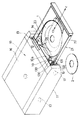
図1において、1は直径が12cmの大径ディスク、2は直径が8cmの小径ディスクである。前面パネル10は底板体11などに取付けられており、その前面部には、No.キー12、オープン・クローズキー13、プレイキー14、ストップキー15などが設けられている。16は本発明のディスク演奏装置19の外装ケース、17は底板体11側に設けられたインシュレーターである。22は前面パネル10の開口部10aから突出されるトレイベースである。23はトレイベース22に案内され矢印イ−ロ方向にスライドできるトレイで、このトレイ23上には、交換したディスク1,2が供給されている。
【0014】
図2、図4、図30、図36において、装置本体20は、底板20Aと、左右の側板20Bと後板20Cなどにより構成されている。前記装置本体20内には、後板20C側にディスク収納位置Aが形成され、そして前面側にディスク演奏位置Bが形成される。ここで、前記ディスク収納位置Aに収納されるディスク1,2の中心と、前記ディスク演奏位置Bで演奏されるディスク1,2の中心との距離Lは、10cm(大径ディスク1の半径+小径ディスク2の半径)より大きくかつ12cm(大径ディスク1の直径)より小さく設定されている。
【0015】
この構成によれば、前記ディスク収納位置Aと前記ディスク演奏位置Bとを近くして、収納された大径ディスク1と演奏中の大径ディスク1とを平面的に重なる位置にできて、装置を小型化できる。また、収納された大径ディスク1と演奏中の小径ディスク2、もしくは収納された小径ディスク2と演奏中の大径ディスク1とは、平面的に重ならない位置にできる。
【0016】
次に、ディスク搬送手段21の構成を、図2、図3において説明する。
すなわち、前記装置本体20内において、ディスク1,2をディスク収納位置Aとディスク演奏位置Bの間で移送するディスク搬送手段21が設けられる。このディスク搬送手段21は、装置本体20の側板20Bに案内されて矢印イ−ロ方向(前後方向)にスライドできるトレイベース22と、このトレイベース22に案内され矢印イ−ロ方向にスライドできるトレイ23と、前記トレイベース22側に支持案内されて矢印イ−ロ方向に摺動可能なキャリア27などにより構成される。そして前記トレイベース22は、矢印イ方向(前方向)へのスライドにより、前面パネル10に形成された開口部10aから突出される。
【0017】
前記トレイ23の上面側には、円筒状に形成された壁23a,23bに囲まれるように、12cmディスク置き部24と8cmディスク置き部25とが同心状に形成されている。その際に、ディスク保持手段のスペーサー(後述する。)の高さを低くして薄型のディスク演奏装置19とするため、12cmディスク置き部24の方が、8cmディスク置き部25よりもやや高い位置に形成されている。
【0018】
前記キャリア27は前記トレイベース22の右側の裏面に設けられ、このキャリア27は条材状であって、外側の側面にはラック28が形成されている。そして前記キャリア27の所定箇所には上下方向の係止孔29が形成され、この係止孔29に対して、前記トレイ23からの係止ピン26が係止されている。
【0019】
以上の22〜29などにより、ディスク搬送手段21の一例が構成される。そして、このディスク搬送手段21によると、水平駆動手段(後述する。)の正逆駆動により、ラック28を介してキャリア27が正逆に移動されることで、このキャリア27と一体のトレイ23がトレイベース22に支持案内されて一体移動される。これにより、前記装置本体20内において、ディスク1,2をディスク収納位置Aとディスク演奏位置Bの間で移送することができる。
【0020】
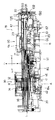
次に、ディスク保持手段30の構成を、図2、図5〜図7、図20、図31、図36において説明する。
前記ディスク収納位置Aにはディスク保持手段30が設けられ、このディスク保持手段30は、複数個のスペーサー38を係脱自在に保持する上下一対のスピンドルである上スピンドル31と下スピンドル41とを有し、下スピンドル41の昇降と前記スペーサー38の垂直駆動によりディスク1,2を前記ディスク搬送手段21との間で受け渡し可能としている。
【0021】
すなわち、32はスピンドル取付板で、前記側板20Bの後半部で上面間に設けられており、その中央下部には前記上スピンドル31が設けられている。また、42はスピンドル取付板32に下方から対向される昇降基台(スピンドルベース)で、昇降手段(後述する。)によって垂直方向に駆動されるよう構成されており、その中央上部には前記下スピンドル41が設けられている。
【0022】
前記上スピンドル31は、上スピンドル本体31aの上端にフランジ31bを有し、このフランジ31bに形成された係合片31cがスピンドル取付板32に形成された係合孔32aに係合する。上スピンドル本体31aの外周部には、ディスク押え33が嵌め込まれており、上スピンドル本体31aの上下方向の溝31eに沿って移動可能である。このディスク押え33は、フランジ31bとの間に設けられたディスク押えばね34によって下方向に付勢されている。
【0023】
上スピンドル本体31aの内部には、保持爪35が収納されている。この保持爪35は、スペーサ38を上スピンドル31に保持するための爪部35aと、下スピンドル41側の凸部44cが突き当たる芯部35bと、上ストッパ35cとからなり、合成樹脂によって一体成形されている。
【0024】
前記保持爪35は、スピンドル取付板32との間に設けられた爪開きばね36によって下方に付勢されているが、押し部31dによって飛び出るのを妨げている。この押し部31dは、上スピンドル本体31aと一体的に成形され、後述する離脱防止爪48の押し下げ片48aの先端が突き当たる。
【0025】
爪部35aは、根元部分が薄板でできているため、内、外方向に曲がるよう構成されている。この爪部35aの先端部35dはフック状になっており、上スピンドル本体31aに接する部分は内側に傾斜している。保持爪35の芯部35bは、爪部35aの先端部35dが上スピンドル本体31a内に十分後退できるように、先端部35dが当たる位置に3本の縦溝35eが形成されている。
【0026】
前記下スピンドル41は、外筒43と内筒44からなる下スピンドル本体45と、内筒44に嵌め込まれた離脱防止爪48などから構成されている。内筒44は昇降基台42に形成された下軸42aに嵌め込まれ、下端の係止片44aが昇降基台42に係合して固定されている。外筒43は下端にフランジ43aを有し、このフランジ43aの底面にリング状ギヤ43bが設けられている。このリング状ギヤ43bは、ギヤ列(後述する。)の第2中間部ギア157と噛み合って、外筒43を回転させる。
【0027】
外筒43の外周部には雄ネジ43cが形成され、この雄ネジ43cに、スペーサ38を上下させるネジ部46が螺合している。ネジ部46には、外筒43の回転と共に回転しないように回転ストッパー47が取り付けられている。この回転ストッパー47は、その一端がネジ部46に、他端が昇降基台42に軸支されている。
【0028】
離脱防止爪48は、外側に開いた3本の爪部48bと、これら爪部48bと爪部48bの間に形成された3本の押し下げ片48aと、下方に突出する下ストッパー48dとから構成されている。
【0029】
内筒44の上部には、爪部48bの先端が出退するための3個の爪孔44bが形成されている(図7参照)。これらの爪孔44bと爪孔44bの間に、押し下げ片48aの先端が突き出るように小孔が形成されている。この離脱防止爪48は、下軸42a内の圧縮ばね49によって上方に押し上げられ、爪部48bの先端部48eが爪孔44bから突出し、押し下げ片48aが小孔から突出している。また、内筒44の上部中央には、保持爪35を押し上げる凸部44cが形成されている。この凸部44cの下部側面は、爪部48bが爪孔44bから出入りしやすいように傾斜している。
【0030】
なお、昇降基台42の左右両側には、外側へのピン50,51が設けられており、その際に一方(右側)のピン50は一本、他方(左側)のピン51は前後に二本が設けられる。また、52は上下送り検出センサであり、フランジ43aの外周に形成されたスリット43dを検出して回転数をカウントするよう構成されている。
【0031】
以上の31〜52などにより、ディスク保持手段30の一例が構成される。そして、このディスク保持手段30は、次のように作動される。
すなわち、図5は下スピンドル41に5枚のディスク1、2が格納され、上スピンドル31と下スピンドル41が離間した状態を示している。昇降手段(後述する。)によって昇降基台42が上昇(矢印ハ方向)すると、この昇降基台42に取り付けられた下スピンドル41も上昇する。
【0032】
下スピンドル41の上昇によって、120°の角度で配置された3個の保持爪35と、離脱防止爪48がお互い同士の間に嵌まり込んで、凸部44cが保持爪35の芯部35bに突き当たる。さらに、凸部44cが爪開きばね36の力に抗しながら保持爪35を押し上げていくと、保持爪35の先端部35dが上スピンドル本体31a内に入り込む。このためスペーサ38が、爪部35aの先端部に妨げられることなく上スピンドル31側に移動される。
【0033】
同時に、離脱防止爪48の押し下げ片48aが、上スピンドル31の押し部31dに突き当たる。押し部31dが圧縮ばね49の力に抗しながら離脱防止爪48を下方向に押し戻すと、離脱防止爪48の爪部48bの先端部48eが、内筒44内に後退する。このため、スペーサ38が下スピンドル41から上スピンドル31側に移動可能となる(図6参照)。
【0034】
上記のよう状態で、ギヤ列の第2中間部ギア157の回転力が、リング状ギヤ43bに伝えられ外筒43を回転させる。この外筒43の回転によって、ネジ部46が下スピンドル41に沿って上昇し、スペーサ38を押し上げる。ネジ部46がディスク1、2を下スピンドル41から上スピンドル31へ移動させ、必要なディスク1、2が上スピンドル31の下端に位置した時に止まる。
【0035】
なお、上スピンドル31のディスク1、2を下スピンドル41に移動させるには外筒43を逆回転しネジ部46を下げればよい。また移動量は、下スピンドル41と一体のフランジ43aの回転数を上下送り検出センサ52がカウントし、このカウント数に基づいて停止などすることで制御される。
【0036】
そして、昇降手段によって昇降基台42が下降(矢印ニ方向)させて、いったん、上スピンドル31と下スピンドル41を離間させた後、上スピンドル31と下スピンドル41の間に、トレイ23を移動させる。
【0037】
上スピンドル31と下スピンドル41が離間すると、爪開きばね36によって保持爪35が下方に押し下げられ、爪部35aの先端部35dが上スピンドル31の外周壁から飛び出し、上スピンドル31に移動したスペーサ38及びディスク1、2を保持する。同時に、離脱防止爪48が圧縮ばね49によって上方に押し上げられ、爪部35aが爪孔44bから突出して下スピンドル41に嵌まっているスペーサ38が下スピンドル41から離脱するのを防止する。
【0038】
上スピンドル31と下スピンドル41の間にトレイ23が移動した状態で再度、昇降手段によって下スピンドル41を上昇させる。下スピンドル41が上スピンドル31に突き当たって、保持爪35の係止状態を解除した状態で、スペーサ38を垂直駆動して1スリット分(下スピンドル41の1回転分)下降駆動したのち、再び、上スピンドル31と下スピンドル41を離間させると、トレイ23に必要なディスク1、2が乗せられ、ディスク演奏位置Bあるいは外部に運びだされる。
【0039】
次に、ディスク演奏手段60の構成を、図2、図4、図8、図19、図30〜図36において説明する。
前記ディスク演奏位置Bには、前記装置本体20側に昇降可能に支持されたディスク演奏手段60が設けられる。このディスク演奏手段60は、矢印ハ−ニ方向に昇降可能な昇降台61を有し、この昇降台61にディスク1,2の記録再生装置62が嵌め込み状に設けられている。そして昇降台61と記録再生装置62との間で複数箇所には、記録再生装置62を上昇付勢する緩衝ばね63が設けられている。前記側板20Bの前半部で上面間に設けられた上部カバー67には、記録再生装置62のディスククランパー64が一定の隙間で支持されている。なお、昇降台61の左右両側には、外側へのピン65,66がそれぞれ一本設けられている。
【0040】
以上の61〜67などにより、ディスク演奏手段60の一例が構成される。このディスク演奏手段60の昇降台61は、昇降手段(後述する。)によって矢印ハ方向に上昇し、ディスク1,2をトレイ23の上面から離したのち、記録再生装置62とディスククランパー64との間でクランプして、記録再生ができるよう構成されている。
【0041】
次に、前記下スピンドル41の昇降と前記ディスク演奏手段60の昇降を行う昇降手段70の構成を、図4、図8、図16、図22、図31、図36において説明する。
【0042】
すなわち、装置本体20内には、この装置本体20の側板20B側に支持案内されて矢印イ−ロ方向に摺動可能な左右一対のプレート71,81が設けられる。そしてプレート71,81の後板20C寄りの端部からは、相対向する方向への突出部72,82が一体に連設され、これら突出部72,82には相対向する方向への長孔73,83が形成されている。
【0043】
一方(右側)のプレート71は単一の部品の一例であって、前記下スピンドル41における昇降基台42の一方に設けられたピン50が係合するカム溝74を後部に有し、そして前部には、内側に向いた上部ラック75と下部ラック76とを有する。また他方(左側)のプレート81は、前記昇降基台42の他方に設けられた一対のピン51が係合する一対のカム溝84と、前記ディスク演奏手段60の他方に設けられたピン66が係合するカム溝85とを、前後に振分けて有する。そして、前記ディスク演奏手段60の一方に設けられたピン65は、カムギヤ(後述する。)側のカム溝96に係合されている。
【0044】
ここで一方のプレート71のカム溝74は、その前部側から後部側に亘って、前上位カム部74a、V字状カム部74b、中間上位カム部74c、後上位カム部74dの連続溝により形成されている(図9、図16参照)。なお、中間上位カム部74cと前上位カム部74aは、後上位カム部74dに対して上位とされている。
【0045】
また他方のプレート81の後部と中間部のカム溝84は、その前部側から後部側に亘って、前上位カム部84a、中間上位カム部84b、V字状カム部84c、後上位カム部84dの連続溝により形成されている(図20、図21参照)。なお、前上位カム部84aは、中間上位カム部84bや後上位カム部84dに対して下位とされている。
【0046】
さらに他方のプレート81の前部のカム溝85は、その前部側から後部側に亘って、前下位カム部85a、中間上位カム部85b、後下位カム部85cの連続溝により形成されている(図20、図31参照)。そしてカムギヤ側のカム溝96は螺旋状に形成されている(図19参照)。
【0047】
前記装置本体20内の後板20C寄りの位置でその底板20Aからは軸86が立設され、この軸86にその中間部を介して回転可能に支持された連結レバー87が設けられる。この連結レバー87の両端にはピン88,89が立設され、これらピン88,89は前記長孔73,83に係合されている。これにより、装置本体20に回転可能に支持された連結レバー87により、前記左右一対のプレート71,81が連結され、以てプレート71,81は互いに逆方向へ摺動される。
【0048】
前記装置本体20内には、前記下部ラック76に噛み合う中間ギヤ90が、底板20A側から立設された軸91を介して回転可能に設けられ、さらに、前記中間ギヤ90に噛み合うカムギヤ92が、軸93を介して回転可能に設けられている。このカムギヤ92の下面側にはカム筒体94が一体化されている。そしてカム筒体94の外周には、前記ディスク演奏手段60の一方に設けられたピン65が係合される前記カム溝96が形成されている。
【0049】
以上の71〜96により昇降手段70の一例が構成される。そして、この昇降手段70によると、水平駆動手段(後述する。)側のギア回転力が上部ラック75を介して一方のプレート71に伝達されることで、この一方のプレート71を矢印イ−ロ方向に摺動させるとともに、連結レバー87を介して他方のプレート81を逆方向へ摺動させる。これと同時に、下部ラック76に噛み合う中間ギヤ90が回転され、そしてカムギヤ92を介してカム筒体94が回転される。
【0050】
このように、左右のプレート71,81が互いに逆方向へ摺動され、そして一方のプレート71の移動に対応してカムギヤ92が回転されることで、カム溝74,84を介して前記下スピンドル41の昇降基台42を矢印ハ−ニ方向に昇降させるとともに、カム溝96,85を介して前記ディスク演奏手段60を矢印ハ−ニ方向に昇降させることになる。なお、カム溝74,84、96,85の形成位置や前述したカム形状は、プレート71,81の移動に伴って、後述するタイミングが好適に行われるように設定されている。
【0051】
すなわち、図16(A)、図21、図31に示すプレイ時では、昇降基台42の一方のピン50はカム溝74の中間上位カム部74cに係合し、昇降基台42の他方のピン51はカム溝84の中間上位カム部84bに係合し、ディスク演奏手段60の他方のピン66はカム溝85の中間上位カム部85bに係合し、ディスク演奏手段60の一方のピン65はカム溝96に係合するように設定されている。
【0052】
また図32に示す下スピンドル下降でかつトレイフロント時では、昇降基台42の一方のピン50はカム溝74のV字状カム部74bに係合し、昇降基台42の他方のピン51はカム溝84のV字状カム部84cに係合し、ディスク演奏手段60の他方のピン66はカム溝85の後下位カム部85cに係合し、ディスク演奏手段60の一方のピン65はカム溝96に係合するように設定されている。
【0053】
また図33に示す下スピンドル下降でかつトレイリヤ時では、昇降基台42の一方のピン50はカム溝74のV字状カム部74bに係合し、昇降基台42の他方のピン51はカム溝84のV字状カム部84cに係合し、ディスク演奏手段60の他方のピン66はカム溝85の後下位カム部85cに係合し、ディスク演奏手段60の一方のピン65はカム溝96に係合するように設定されている。
【0054】
また図16(C)、図34に示すディスクストック時では、昇降基台42の一方のピン50はカム溝74のV字状カム部74bに係合し、昇降基台42の他方のピン51はカム溝84のV字状カム部84cに係合し、ディスク演奏手段60の他方のピン66はカム溝85の後下位カム部85cに係合し、ディスク演奏手段60の一方のピン65はカム溝96に係合するように設定されている。
【0055】
また図16(B)、図35示すディスクチェンジ状態では、昇降基台42の一方のピン50はカム溝74の前上位カム部74aに係合し、昇降基台42の他方のピン51はカム溝84の前上位カム部84aに係合し、ディスク演奏手段60の他方のピン66はカム溝85の中間上位カム部85bに係合し、ディスク演奏手段60の一方のピン65はカム溝96に係合するように設定されている。
【0056】
上述したように前記昇降手段70は、単一の部品である一方のプレート71の移動が同時に、前記下スピンドル41の昇降と前記ディスク演奏手段60の昇降に作用するように構成されている。したがって、ディスク保持手段30の下スピンドル41の昇降と、ディスク演奏手段60の昇降を同一のプレート71により駆動することで、容易に双方の昇降のタイミングを合わせることができ、昇降中の演奏ディスクと収納部の保持ディスクの隙間が変化することなく昇降できるので、昇降中のディスク同士の接触を防ぐことができる。
【0057】
また、ディスク保持手段30の下スピンドル41の昇降とディスク演奏手段60の昇降とを、カム溝74、84,85を有するプレート71,81により駆動するよう構成したことにより、下スピンドル41の昇降とディスク演奏手段60の昇降とを、簡単な構成でタイミングがずれることなく行える。
【0058】
さらに、下スピンドル41とディスク演奏手段60の、共通の昇降手段70の一部に、左右一対のプレート71,81と、中間ギヤ90で連結されプレート71の移動と同期して回転するカムギヤ92を用いた構成により、ディスク演奏手段60の左右に設けられたピン65,66の幅方向のピッチと下スピンドル41の昇降基台42の左右に設けられたピン50,51の幅方向のピッチが違うときでも、簡単な構成のまま、双方の昇降のタイミングがずれることなく、昇降を行える。
【0059】
次に、前記ディスク搬送手段21と前記昇降手段70を駆動可能な水平駆動手段100の構成を、図9〜図15、図17、図36において説明する。
すなわち、水平駆動手段100は、減速機構(後述する。)を介して駆動源に接続された駆動ギヤ101を有し、この駆動ギヤ101は、底板20A側から立設された軸102に回転可能に取付けられている。前記デイスク搬送手段21のキャリア27側およびトレイベース22に支持案内されて矢印イ−ロ方向に相対的に摺動可能な駆動ラック103が設けられ、この駆動ラック103のラック104は内側の側面に形成され、前記駆動ギヤ101と噛み合っている。
【0060】
前記駆動ラック103の所定箇所には、軸105を介して増速ギヤ106が回転可能に設けられている。この増速ギヤ106は、同数歯でかつモジュールの異なる大小2つのギヤ106A,106Bで構成された2段ギヤであり、前記小ギヤ106Bが前記昇降手段70側に設けられた一方のプレート71のラック75に噛み合い、かつ前記大ギヤ106Aが前記ディスク搬送手段21側に設けられたキャリア27のラック28に噛み合っている。
【0061】
前記トレイベース22の前部側には、キャリア27ならびにプレート71の矢印イ方向への摺動を規制するストッパ具110と、キャリア27の矢印ロ方向への摺動を阻止するキャリアロック具112とが設けられている。
【0062】
すなわちストッパ具110はL字形のレバー形式であって、トレイベース22側にピン111を介して回動可能に設けられており、その一方の腕部は、前記キャリア27の前端部に形成された当接部27aが当接可能な受止め部110aに形成されている。また他方の腕部には、前記プレート71の先端に形成された先端当接部71dが当接可能な受止め部110bと、前記キャリア27側に係合可能な係止部110cとが形成されている。
【0063】
この係止部110cは、前記キャリア27の当接部27aが受止め部110aに当接されてストッパ具110がピン111の周りに所定量回転されたときに、前記キャリア27の外側面に形成されている係止凹部27bに係合されるように構成されている。
【0064】
前記キャリアロック具112もL字形のレバー形式であって、トレイベース22側にピン113を介して回動可能に設けられており、その一方の腕部は、前記キャリア27の内側面に形成されているストッパ用凹部27cに係合可能なストッパ部112aに形成されている。また他方の腕部には、ロック解除用の回転受け部112bに形成されている。
【0065】
前記ストッパ具110とキャリアロック具112とに亘って、これらストッパ具110とキャリアロック具112を回転付勢する共通の付勢ばね114が設けられている。ここで付勢ばね114は、ストッパ具110を解除方向に付勢し、キャリアロック具112を係合方向へ付勢するように配設されている。
【0066】
前記装置本体20の前部には、前記キャリアロック具112をロック解除方向へ回動させるためなどの操作具115が設けられる。この操作具115はレバー形式であって、装置本体20側にピン116を介して回動可能に設けられている。
【0067】
この操作具115の第一の腕部には、前記一方のプレート71側に形成された前部当接部71aが当接可能な受止め部115aが形成されている。また第二の腕部には、前記キャリアロック具112のロック解除用の回転受け部112bに後部側から当接可能な回転操作部115bが形成されている。そして第三の腕部には、前記トレイベース22の下面側に設けられたロック用カム溝22aに対して横方向から係脱可能なカムピン115cが形成されている。なおロック用カム溝22aは、カムピン115cの移動軌跡に沿うように曲面形成されている。
【0068】
前記操作具115を回動付勢するためのばね117が設けられ、その際に付勢方向は、受止め部115aが後部側へ移行するように設定されている。
前記装置本体20の中間部には、矢印イ方向へ最も移動した一方のプレート71が矢印ロ方向へ移動することを阻止するとともに、トレイベース22の矢印ロ方向へ移動限を規制する中間ロック具120が設けられる。この中間ロック具120はレバー形式であって、その中央部位置が、装置本体20側にピン121を介して回動可能に設けられている。
【0069】
前記中間ロック具120の前端には、前記プレート71の中間部に設けられた中間当接部71bが当接可能な受止め部120aが形成されている。そして中間ロック具120の後部寄りの位置には、トレイベース22の後部寄りの位置に設けられた駆動カム部22b(図3参照)が当接自在な受動カム部120bが形成されている。また中間ロック具120の後端には、トレイベース22の後部寄りの位置に設けられた被ストッパ部22c(図3参照)が当接自在なストッパ部120cが形成されている。なお中間ロック具120は、受止め部120aが後部当接部71bの移動軌跡内に突入されるように、ばね122により付勢されている。
【0070】
前記装置本体20の後部には、矢印ロ方向へ移動した一方のプレート71を一旦受け止めるとともに、一方のプレート71がさらに矢印ロ方向へ最も移動したときにキャリヤ27のロックを行うリヤロック具123が設けられる。このリヤロック具123はL字形のレバー形式であって、その中央部位置が、装置本体20側にピン124を介して回動可能に設けられている。
【0071】
前記リヤロック具123の前向き腕部の前端には、前記プレート71の後端に設けられた後端当接部71cが当接可能な受止め部123aが形成されている。そしてリヤロック具123の横向き腕部には、キャリヤ27の後端に設けられた後端当接部27dが当接可能な当接部123bが形成されている。また受止め部123aの部分には、キャリヤ27の後部寄りの位置に設けられた外側開放の係止凹部27eに対して外側から係脱自在な係止部123cが形成されている。なおリヤロック具123は、受止め部123aが後端当接部71cの移動軌跡内に突入されるように、ばね125により付勢されている。
【0072】
以上の101〜125によって、前記ディスク搬送手段21と前記昇降手段70を駆動可能な水平駆動手段100の一例が構成される。この水平駆動手段100によると、減速機構を介して駆動源により駆動ギヤ101を正逆に回転駆動することで、駆動ラック103を矢印イ−ロ方向に摺動させる。そして駆動ラック103の摺動により、増速ギヤ106などを介して前記ディスク搬送手段21と前記昇降手段70とを駆動させる。
【0073】
すなわち、たとえば図11の(A)に示すプレイ時には、キャリア27は前端限まで移動され、その当接部27aが受止め部110aに当接されることで、ストッパ具110は付勢ばね114に抗して回動され、以て係止部110cが前記キャリア27の係止凹部27bに係合されている。これによりキャリア27の前端限への移動位置が維持されている。またキャリアロック具112も、その回転受け部112bが操作具115の回転操作部115bに当接されることで、付勢ばね114に抗して回動され、ストッパ用凹部27cに対してストッパ部112aが離脱されている。
【0074】
そして中間ロック具120は、その受動カム部120bにトレイベース22の駆動カム部22bが作用されることでばね122に抗して回動され、その受止め部120aを後部当接部71bの移動軌跡外に位置させている。さらにリヤロック具123は、ばね125の付勢力により回動され、受止め部123aが後端当接部71cの移動軌跡内に突入されている。また昇降手段70は、一方のプレート71が前端側へ摺動されていることで上昇作動され、以て下スピンドル41ならびに記録再生装置62を上昇させている。
【0075】
このようなプレイ時から、演奏を終えたディスク1,2をディスク収納位置Aに戻すとき、まず駆動ギヤ101を図11の(B)において矢印ホの方向へ回転させる。これにより駆動ラック103が矢印ロ方向に摺動されるが、このとき、キャリア27はストッパ具110により移動が阻止されていることから、駆動ラック103に軸支されている増速ギヤ106は、キャリア27のラック28に対して大ギヤ106Aを噛み合わせ回転させることになる。
【0076】
その結果、増速ギヤ106の小ギヤ106Bの回転によって、上部ラック75を介して一方のプレート71が矢印ロ方向に摺動され、その摺動は後端当接部71cが受止め部123aに当接するまで行われる。
【0077】
前述した一方のプレート71の矢印ロ方向への摺動によって、昇降手段70は下降作動されることになり、以て下スピンドル41ならびに記録再生装置62を下降させる。その際に増速ギヤ106では減速伝動状態になり、以て下降は緩やかに安定して行われる。以上により、図11の(B)に示す下スピンドル下降でトレイフロント時となる。
【0078】
一方のプレート71の摺動が、後端当接部71cが受止め部123aに当接して停止された状態において、駆動ラック103の矢印ロ方向に摺動によって、駆動ラック103に軸支されている増速ギヤ106は、固定状の上部ラック75に対して小ギヤ106Bが噛み合わせ回転されることになる。その結果、図12の(A)に示すように、増速ギヤ106の大ギヤ106Aの回転によって、ラック28を介してキャリア27が矢印ロ方向に摺動され、その際にストッパ具110は、付勢ばね114によって回動され、以て係止部110cが前記キャリア27の係止凹部27bから離脱されている。
【0079】
このようなキャリア27の摺動は、後端当接部27dが当接部123bに当接するまで行われる。この当接により、ばね125に抗してロック具123が回動され、係止凹部27eに対して係止部123cが外側から係合されることになって、キャリヤ27は後端限への移動位置がロックされる。そしてキャリヤ27の摺動により、トレイベース22に対してトレイ23を矢印ロ方向に摺動させることになり、以て図12の(A)に示す下スピンドル下降でトレイリヤ時となる。なお、ロック具123のロック回動によって、プレート71の後端当接部71cに対して受止め部123aが内側に逃げることになる。
これによりプレート71の矢印ロ方向への摺動が可能となり、したがって、一方のプレート71が矢印ロ方向へ摺動されることで、昇降手段70を上昇作動させることになり、以て下スピンドル41ならびに記録再生装置62を上昇させて、図12の(B)に示すストック時となる。
【0080】
上述したストック時から図13に示すチェンジ時へと動作させるに、まず駆動ギヤ101を前述とは逆回転、すなわち矢印ヘの方向に回転させる。これにより駆動ラック103が矢印イ方向に摺動されるが、このとき、キャリア27はリヤロック具123により移動が阻止されていることから、駆動ラック103に軸支されている増速ギヤ106は、キャリア27の固定状のラック28に対して大ギヤ106Aを噛み合わせ回転されることになる。
【0081】
その結果、増速ギヤ106の小ギヤ106Bの回転によって、上部ラック75を介して一方のプレート71が矢印イ方向に摺動される。これにより昇降手段70を下降作動させることになり、以て下スピンドル41ならびに記録再生装置62を下降させる。
【0082】
このように一方のプレート71が矢印イ方向に摺動され、プレート71の先端当接部71dがロック具110の受け止め部110dに当接して停止された状態で、ロック具123はロック解除方向へ回動可能となり、以てロック具123はばね125によってロック解除方向へ回動され、係止凹部27eに対して係止部123cが外側へ離脱される。そして駆動ラック103の矢印イ方向に摺動によって、駆動ラック103に軸支されている増速ギヤ106は、固定状の上部ラック75に対して小ギヤ106Bが噛み合わせ回転されることになる。
【0083】
その結果、増速ギヤ106の大ギヤ106Aの回転によって、ラック28を介してキャリヤ27が矢印イ方向に送り出され、以て駆動ラック103の移動に伴ってキャリヤ27は増速されて矢印イ方向に摺動される。そして、キャリア27の摺動は、キャリア27の当接部27aがロック具110の受け止め部110aに当接されるまで行われる。このキャリア27の摺動により、トレイベース22に対してトレイ23を矢印イ方向に摺動させることになる。また、当接部27aが受け止め部110aに当接されることで、ストッパ具110は付勢ばね114に抗して回動され、以て係止部110cが前記キャリア27の係止凹部27bに係合される。これにより、キャリア27の前端限への移動位置が維持されている。なお、ストッパ具110のロック回動によって、プレート71の先端当接部71dに対して受止め部110bが内側に逃げることになる。
【0084】
これによりプレート71の矢印イ方向への摺動が可能となり、したがって一方のプレート71が矢印イ方向へ摺動されることで、昇降手段70を上昇作動させることになり、以て下スピンドル41ならびに記録再生装置62を上昇させて、図13に示すチェンジ時となる。
【0085】
図14の(A)に示されるクローズ時には、図11の(A)に示されるプレイ時に対して、一方のプレート71が矢印イ方向にさらに摺動されている。これにより昇降手段70を下降作動させることになり、以て下スピンドル41ならびに記録再生装置62を下降させる。
【0086】
このような図14の(A)に示されるクローズ時において、駆動ギヤ101を矢印ヘの方向へ回転させることにより、図14の(B)に示されるオープン時にし得る。すなわち、駆動ギヤ101の回転により駆動ラック103が矢印イ方向に摺動され、装置本体20の前部に設けられたストッパー(図示せず)に当接して矢印イ方向に停止状態のプレート71上の上部ラック75に対して小ギヤ106Bが噛み合わせ回転され、増速ギヤ106の大ギヤ106Aの回転によりラック28を介してキャリア27が矢印イ方向に摺動される。このとき、前記キャリアロック具112は付勢ばね114により回動され、図14の(B)や図15に示されるように、そのストッパ部112aを前記キャリア27のストッパ用凹部27cに係合させ、以てキャリア27のロックを行っている。このキャリアロック具112の作用により、キャリア27に一体状のトレイベース22ならびにトレイ23を矢印イ方向に突出移動させる。
【0087】
なお、図14の(B)に示されるオープン時から図14の(A)に示されるクローズ時への、トレイベース22ならびにトレイ23の矢印ロ方向への移動は、駆動ギヤ101を矢印ホ方向に回転させることにより行える。
【0088】
このような水平駆動手段100によると、動作負荷の大きく異なるトレイ23の駆動と両スピンドル31,41およびディスク演奏手段60の昇降手段70の駆動を、同数歯で大小2段のギヤ106A,106Bのモジュール、つまりピッチ円径をそれぞれ自由に選定することにより、共通の駆動源から伝達された駆動力をトレイ23と昇降手段70の負荷と必要な速度にあわせて自由に設定することができる。
【0089】
次に、正逆駆動自在なモーターからなる駆動源140の回転を水平駆動手段100の駆動ギヤ101に接続させる減速機構141の構成、前記水平駆動手段100側に設けられたギヤ列149の構成、前記スペーサー38の垂直駆動系に設けられたギヤ列151の構成などを、図17、図18、図36において説明する。
【0090】
すなわち、正逆駆動自在なモーターからなる駆動源140は装置本体20の前部側に固定され、その出力軸142に取付けた伝動プーリ143と、装置本体20の中間部側に軸144を介して回転可能に設けた受動プーリ145との間に弾性ベルト146が懸架されている。そして前記受動プーリ145の下面側には筒状ギヤ147が固定されている。以上の142〜147によって駆動源140の回転を駆動ギヤ101に接続させる減速機構141の一例が構成される。
【0091】
前記水平駆動手段100側に設けられるギヤ列149は、水平駆動手段100の前記駆動ギヤ101と、この駆動ギヤ101に一体化されている大径の受動ギヤ108などにより、その一例が構成される。
【0092】
前記スペーサー38の垂直駆動系に設けられたギヤ列151は、前記筒状ギヤ147に対向して設けられた受動ギヤ152を有し、この受動ギヤ152は、装置本体20側に軸153を介して回転可能に設けられている。そして前記受動ギヤ152の下面側には筒状の伝動ギヤ154が固定されている。前記デイスク保持手段30の昇降基台42には、前記伝動ギヤ154に常時噛み合う第1中間部ギヤ155が軸156を介して回転可能に設けられ、そして第1中間部ギヤ155に常時噛み合う第2中間部ギヤ157が軸158を介して回転可能に設けられている。
【0093】
以上の152〜158によって、前記スペーサー38の垂直駆動系に設けられたギヤ列151の一例が構成される。なお前記第2中間部ギヤ157は、前記デイスク保持手段30のリング状ギヤ43bに常時噛み合っている。
【0094】
次に、切換ギヤ161と、この切換ギヤ161を軸方向に摺動させる駆動切換手段165の構成を、図17、図18、図36において説明する。すなわち切換ギヤ161は、前記筒状ギヤ147、前記受動ギヤ108、前記受動ギヤ152の全てに対向して設けられている。
【0095】
この切換ギヤ161は、装置本体20側からの軸162に対して軸方向に摺動可能(昇降可能)ならびに回転可能に設けられている。そして切換ギヤ161は、前記筒状ギヤ147に常時噛み合っている大径ギヤ部161Aと、この大径ギヤ部161Aの下面に設けられた小径ギヤ部161Bからなる。前記切換ギヤ161は、圧縮ばね163によって下降付勢され、そしてプランジャーやレバーなどからなる駆動切換手段165の退入動によって、圧縮ばね163に抗して上昇されるように構成されている。
【0096】
さらに切換ギヤ161は、駆動切換手段165が非作動で圧縮ばね163の弾性力により下降されたとき、その小径ギヤ部161Bが前記受動ギヤ108に噛み合い、また駆動切換手段165が作動で圧縮ばね163の弾性力に抗して上昇されたとき、その大径ギヤ部161Aが前記受動ギヤ152に噛み合うように構成されている。
【0097】
これにより前記切換ギヤ161は、減速機構141を介して駆動源140に接続されるとともに、駆動切換手段165の作動による軸方向への摺動により、前記水平駆動手段100に設けられたギヤ列149もしくは前記スペーサー38の昇降の駆動系に設けられたギヤ列151のどちらか一方のギヤ列に選択的に噛み合い可能となる。
【0098】
上記構成の減速機構141、ギヤ列149、ギヤ列151、切換ギヤ161などの構成によると、駆動源140の正逆駆動は、弾性ベルト146を有する減速機構141を介して筒状ギヤ147に伝達され、この筒状ギヤ147を減速して正逆回転させる。そして駆動切換手段165による前記切換ギヤ161の摺動中に、少なくとも前記切換ギヤ161の回転駆動、停止、反転駆動を含む切換モードを有することになる。その際に前述した正逆の切換モードは、前記駆動源140の切換開始直前の回転方向に対して反転から開始するように制御されている。
【0099】
すなわち、図37において、
モード切換えAは、プレイからチェンジ後上昇、またはプレイ、チェンジからストック後上昇
モード切換えBは、上昇後チェンジからプレイ、オープン、またはストック上昇後からチェンジ、オープン
モード切換えCは、ストックからチェンジ後上昇
モード切換えDは、ストックからチェンジ後下降
モード切換えEは、上昇後チェンジからストック
モード切換えFは、プレイからチェンジ後下降、またはプレイ、チェンジからストック後下降
モード切換えGは、下降後チェンジからストック
モード切換えHは、上昇後チェンジからプレイ、オープン、またはストック下降後からチェンジ、オープン
であり、いずれのモードの場合にも、駆動切換手段165による前記切換ギヤ161の正逆の摺動中に、駆動源140は、正転に対して逆転から開始するか、逆転に対して正転から開始するように制御されている。
【0100】
すなわち、たとえばモード切換えAにおいて、駆動源140の正転または逆転の各線は、上位がブレーキオン、下位がブレーキオフを示している。したがって、M域では、正転、逆転ともにブレーキオンであることから回転停止であり、また駆動切換手段165の摺動中に、N域では、逆転がブレーキオフとなって逆転が開始され、そしてO域では、正転がブレーキオフ、逆転がブレーキオンとなって所期の正転が行われる。
【0101】
前記駆動切換手段165が作動で圧縮ばね163の弾性力に抗して切換ギヤ161が上昇されたときには、図18(A)に示されるように、筒状ギヤ147に噛み合っている大径ギヤ部161Aが前記受動ギヤ152に噛み合うことになる。これにより、切換ギヤ161の切換摺動完了後、駆動源140の正逆駆動は、ギヤ列151を介してディスク保持手段30のリング状ギヤ43bに伝達され、このリング状ギヤ43bを正逆に回転させる。
【0102】
また駆動切換手段165が非作動で圧縮ばね163の弾性力により切換ギヤ161が下降されたときには、図18(B)に示されるように、大径ギヤ部161Aの前記受動ギヤ152に対する噛み合いが外れ、そして小径ギヤ部161Bが前記受動ギヤ108に噛み合うことになる。これにより、駆動源140の正逆駆動は、ギヤ列149を介して水平駆動手段100の駆動ギヤ101に伝達され、この駆動ギヤ101を正逆に回転させる。
【0103】
このような動作において、前記駆動切換手段165による切換ギヤ161の摺動中に、切換ギヤ161の回転駆動、停止、反転駆動を含む切換モードを有することで、2つの駆動系への切換を行う切換ギヤ161の、切換時の各駆動系のギヤ列149,151への噛み合いの入り込みが、わずかに回転、停止、反転を繰り返しながら行われるため、歯の先端同士で当たって切換ギヤ161の摺動が妨げられることなく確実に行えることができ、以て駆動源140の共用化と駆動系の一部共用化ができて、部品数が減らせるとともに装置の小型化ができる。
【0104】
そして減速機構141の一部に弾性ベルト146を用いることで、駆動源140の駆動が停止したときに弾性ベルト146の側圧が駆動系に残ることになって、切換ギヤ161が切り換え前に接続していた駆動系の歯との噛み合いから抜けるときに負荷が大きくなるため、回転、停止、反転の繰り返しがさらに有効に作用することになる。
【0105】
また、駆動切り換え時の、切換ギヤ161の最初の回転方向を、切り換え前に接続していた駆動系の停止直前の回転方向と逆の方向から回転し始めるように制御したことにより、駆動停止後の駆動の慣性による回転を停止させる作用が働き、切り換え前の駆動停止後から切換モードに移行するまでの待ち時間を短縮できて、ディスク交換時間を短縮できる。また、前述したように弾性ベルト146を用いた構成では、弾性ベルト146の側圧による切換負荷の低減に特に有効となる。
【0106】
次に、ディスク隙間確保手段170の構成を、図19〜図21において説明する。すなわちディスク隙間確保手段170は、演奏ディスクに対して上下に隣接する収納ディスクの間に進入可能に構成されている。このディスク隙間確保手段170は、前記ディスク演奏位置Bと前記ディスク収納位置Aとの間に設けられるもので、前記下スピンドル41の昇降基台42に回動可能に支持された軸部分171と、この軸部分171に対して左右方向の二箇所から連設されたレバー172とにより構成されている。
【0107】
そして両レバー172の先端部分には、隣接する収納ディスクの間に進入可能な進入部173が設けられ、これら進入部173は、鋭角の接合部を持つ2つの平滑な平面173a,173bで構成され、各平面173a,173bで上下それぞれのディスクの端面に直接接触して、隣接ディスクを上下に押し広げることが可能(なお、上下に押し広げることなく進入させる構成でもよい。)に構成されている。その際に前記ディスク隙間確保手段170の二箇所の進入部173は、演奏ディスクと収納ディスクの共通の中心線を挟んで略対称な位置に設けられている。
【0108】
前記ディスク隙間確保手段170は、前記昇降手段70により駆動されるように構成されている。すなわちディスク隙間確保手段170は、前記昇降基台42側との間に設けられたばね174によって、そのレバー172を起立させ、進入部173を上下のディスクの端面間から後退させるように構成されている。そして、軸部分171の端には、レバー状のカム従動体175が設けられ、また他方のプレート81の内面にはカム体176が設けられている。
【0109】
以上の171〜176によりディスク隙間確保手段170の一例が構成される。そして、このディスク隙間確保手段170によると、前記プレート81がディスク演奏位置Bに移動して、前記カム従動体175がカム体176に作用することで、ばね174に抗してレバー172をディスク収納位置A側へ傾倒させ、その進入部173を隣接する収納ディスクの間に進入させることになる。
【0110】
したがって、前述したように、装置を小型化するために、ディスク収納位置Aとディスク演奏位置Bとを近くして、収納されたディスク1、2と演奏中のディスク1、2を平面的に重なる位置に構成しても、ディスク隙間確保手段170が、演奏ディスクに隣接する上下の収納ディスクの隙間に進入するとともに、振動等が作用したときでも隙間が狭くなることを防ぐことになり、演奏ディスクと収納ディスクの接触による音飛びやディスク傷の発生を防止できる。
【0111】
また、ディスク隙間確保手段170としてレバー172を有する構成にしたことにより、ディスク隙間確保手段170の位置決めが簡単に行え、簡単な構成で安定して隙間確保を行うことができる。さらに、ディスク隙間確保手段170を昇降手段70で駆動するように構成したことにより、昇降手段70による下スピンドル41の昇降のタイミングや、ディスク演奏手段60の昇降のタイミングに対してずれることなく、ディスク隙間確保手段170の駆動を行える。
【0112】
さらに、ディスク隙間確保手段170をディスク収納位置Aとディスク演奏位置Bの間に設けたことにより、ディスク収納位置Aとディスク演奏位置Bの両方に近い位置で隙間確保ができるため、隙間確保は正確に行えることなる。
【0113】
そして、ディスク隙間確保手段170は、隣接ディスクの間への進入部173を、ディスク1,2の中心に対しておおよそ左右対称な二箇所に設けて構成したことにより、収納ディスクが演奏ディスクに対して傾斜することを左右の進入部173で阻止されるため、装置の傾斜や振動等の作用の形態に関わらず、安定して隙間を確保できる。
【0114】
さらに、ディスク隙間確保手段170の進入部173を、鋭角の接合部を持つ平面で構成したことにより、演奏ディスクの上下に隣接する2枚の収納ディスクの間にディスク隙間確保手段170の先端が入り込んでいくときに、ディスク1,2の隙間に対して一点で狙えるので、ディスク隙間確保手段170が入り込んでいくときの位置ずれに対する余裕が確保できる。また、ディスクの接触面を平滑な平面173a,173bにすることにより、ディスク1,2の端面に対する摺動の負荷が低減でき、ディスク端との接触での突っ掛かりを防ぐことができる。
【0115】
次に、前記装置本体20に回転可能に支持され、かつ前記トレイ23の前記第2の位置への突出により発生した開口部10aの少なくとも一部を隠蔽可能な隠蔽手段130の構成を、図1、図4、図22〜図27において説明する。ここで、装置本体20内のディスク演奏可能な第1の位置とはディスク演奏位置Bのことであり、そして装置本体20から突出してディスクを取り出し交換可能な第2の位置とはトレイ23が突出したディスク取り出し交換位置Cのことである。
【0116】
前記隠蔽手段130は、前記装置本体20に回転可能に支持されかつ前記トレイ23の移動に対応して回動するレバー131を有する。このレバー131は左右一対であって、装置本体20に回転可能に支持された左右方向の回動軸132に一体化されている。その際に前記レバー131の形状が、前記トレイ23に載置されるディスク1,2の中心に対して略左右対称な位置で、かつ小径ディスク2の外径より狭い間隔で設けられた一対の凸部133を有している。そして前記凸部133の相対向する端部は、各々鋸歯状の凹凸面133aに形成されている。
【0117】
さらに前記回動軸132の他方の端(左端)には受動レバー134が一体化され、この受動レバー134には、レバー131ならびに受動レバー134が後部側へ回動されて水平状姿勢になったときに、後部側へ向く受動カム135が一体に設けられている。
【0118】
そして前記トレイベース22の他側側で前後中間部の下面には、トレイ23とともにトレイベース22が矢印イ方向へ突出移動されたときに、前記受動カム135の下に潜り込んでこの受動カム135を起立回動させるカム22dが形成されている。これにより、レバー131の回動を、前記トレイベース22に設けられたカム22dが前記トレイ23の突出に伴って前記レバー131の一部に接触するとともに付勢して回動するように構成されている。
【0119】
さらに前記トレイベース22の他側側で前後中間部から前端に亘っての下面にはカム条体22eが形成されている。このカム条体22eは、起立回動された受動カム135に前側から当接して、この受動カム135を横倒回動させるとともに、横倒した受動カム135の上側に位置して、前記トレイ23の移動中に受動カム135が起立回動の方向に振れることを阻止するように構成されている。
【0120】
以上の131〜135により隠蔽手段130の一例が構成される。そして、この隠蔽手段130によると、図22、図23に示されるように、前記トレイベース22とともにトレイ23が矢印ロ方向に移動されて、トレイ23がデイスク演奏位置Bにあるときには、受動カム135とともに受動レバー134ならびにレバー131が後部側へ横倒回動されている。
【0121】
そしてトレイ23を、デイスク演奏位置Bからディスク取り出し交換位置Cへと突出させる際には、図24に示されるように、カム条体22eが横倒した受動カム135の上側に位置して、受動レバー134ならびにレバー131が起立回動の方向に振れることが阻止される。
【0122】
このような突出移動によってトレイ23がディスク取り出し交換位置Cへ突出移動されたときには、図25〜図27に示されるように、前記トレイベース22側のカム22dが前記受動カム135の下に潜り込み、そしてカム作用によって受動カム135を起立回動させることになる。すると、この受動カム135の起立回動によって、回動軸132を介して左右一対のレバー131が一体回動され、以て両レバー131は起立状となる。
【0123】
これにより、前記トレイ23の前記ディスク取り出し交換位置Cへの突出により発生した開口部11aの両側部分(少なくとも一部)が、両レバー131に一体の凸部133により隠蔽されることになる。この状態で、ディスク取り出し交換位置Cのトレイ23に対して、ディスク1,2の取り出しや交換が手動により行われる。その後、前記トレイベース22とともにトレイ23が矢印ロ方向に移動されることで、カム条体22eが起立回動された受動カム135に前側から当接して、この受動カム135を自動的に横倒回動させ、以て図22、図23に示されるように、トレイ23はデイスク演奏位置Bに戻される。
【0124】
前述したように、ディスク1,2の取り出しや交換を手動により行う際に、たとえば小径ディスク2を、トレイ23のオープンにより発生した開口部11aから誤って装置本体20内に落とし込みそうになったときでも、図25〜図27の各仮想線に示されるように、小径ディスク2の外径より狭い間隔で設けられた一対の凸部133に形成された鋸歯状の凹凸面133a間に、小径ディスク2の端部が引っかかることになり、以て装置本体20内への小径ディスク2の落ち込みを防止できる。
【0125】
その際に、鋸歯状の凹凸面133a間に引っかかって上下の移動も阻止する状態になり、以て小径ディスク2の端部が浮き上がって凸部133を乗り越えるようなことを防止でき、引っかかり状態が堅持される。
前述したように、レバー131などの回動を、トレイ23のオープン/クローズ時にトレイ23側に設けたカム22dやカム条体22eにより自動的に駆動するように構成したことにより、ディスク1,2をレバー131に接触させた状態で装置本体20の奥方向に押された場合でも、レバー131などが回動して倒れることがなく、ディスク1,2の装置本体20内への落ち込みを確実に防止できる。
次にオープンしたトレイにディスクをずれて載置したままクローズしたときの装置内へのディスク落ち込み防止手段の一例である左右一対の凸部190の構成を、図1、図4、図23〜図29において説明する。
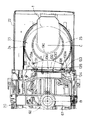
前記左右一対の凸部190は、上部カバー67の前面下方に位置する前面リブ67aの下端から装置本体20の前方に突出する形で、前記トレイ23に載置されるディスク1,2の中心に対しておおよそ左右対称な位置に左右同形状で形成されている。前記凸部190は、各々が前記トレイ23のディスク載置面に略平行な底面191と、前記底面191の前側の先端から上方にかけて形成された装置本体20に対して前下がりの傾斜を持った傾斜面192の2面に挟まれる形の鋭角の先端を有している。
前記底面191はトレイ23のディスク載置面に載置されたディスク(厚さ1.2mm)の上面よりおおよそ1mm上方に形成されている。また、前記トレイ23は、ディスク載置面に載置されたディスク1,2の周囲にディスク上面からおおよそ6mmの高さの円筒状に形成された壁23a,23bを有している。これら壁23a,23bは、載置されたディスク1,2の外周からおおよそ0.5mm外側に、ディスク1,2の前側をほぼ覆うように形成されている。
図28の実線は、前記トレイ23上にディスク1(または2)が通常のディスク載置位置からずれて載置された場合の装置前方から見たディスク1(2)と凸部190の位置関係を示す。このとき、ずれて載置されたディスク1(2)は、壁23a(23b)の上面に一部が乗り上げるような形で傾斜するため、ディスク1(2)の底面は凸部190の底面191より上方に位置している(図29の仮想線ホ参照。)。
【0126】
この状態でトレイ23をクローズすると、ディスク1(2)は、左右一対の凸部190に設けられた鋭角の先端に、その外周部が引っかかる(図29の仮想線ヘ参照。)。さらに、トレイ23がクローズしていくときのトレイ23の移動(推力)により、ディスク1(2)はクローズ方向(後方)に力を受けるが、ディスク1(2)の底面が凸部190に乗り上げているため、左右一対の凸部190の前面に設けた傾斜面192に沿ってディスク1(2)は上方への力を受け、以て開口部10aよりも上方に押し上げられる。
【0127】
これにより、ディスク先端が下方に移動して上部カバー67の前面リブ67aの下側に潜り込むことを確実に防ぐことができ、装置本体20の内部にディスク1(2)が落ち込むことを防止できる。
【0128】
次に、制御の一部を司る検出手段180の構成を、図3、図16において説明する。すなわち検出手段180は、装置本体20側に一体化された固定基板181側に設けられた検出スイッチ群と、一方のプレート71やトレイベース22側に設けられた操作カム群とからなる。ここで固定基板181側に設けられる検出スイッチ群は、前部側から後部側へと順に配置された、オープンスイッチ182と第1スイッチ183と第2スイッチ184とからなる。
【0129】
また一方のプレート71には、第1スイッチ183と第2スイッチ184とを同時にオンさせる第1操作カム185と第2操作カム186とが設けられ、そして第1スイッチ183のみをオンさせる第3操作カム187が設けられ、さらに第2スイッチ184のみをオンさせる第4操作カム188が設けられる。なお、図3に示すようにトレイベース22側には、前記オープンスイッチ182のみをオンさせる第5操作カム189が設けられる。
【0130】
以上の181〜189により検出手段180の一例が構成される。そして、この検出手段180によると、一方のプレート71が前述した演奏位置へ移動した時に、第1操作カム185と第2操作カム186とが第1スイッチ183と第2スイッチ184とを同時にオンさせ、以て演奏位置への移動によるプレイ時を検出し、制御し得る(図16のA参照)。そして、一方のプレート71が前述したチェンジ位置へ移動した時に、第3操作カム187が第1スイッチ183のみをオンさせ、以てチェンジ位置への移動によるチェンジ時を検出し、制御し得る(図16のB参照)。
【0131】
さらに、一方のプレート71が前述したストック位置へ移動した時に、第4操作カム188が第2スイッチ184のみをオンさせ、以てストック位置への移動によるストック時を検出し、制御し得る(図16のC参照)。また、トレイベース22側には、このトレイベース22が突出されたオープン時に、第5操作カム189がオープンスイッチ182のみをオンさせ、以てオープン時を検出し、制御し得る。
【0132】
以上のように構成された本発明の実施の形態の一例であるディスク演奏装置19の動作を説明する。
なお、動作説明において図38のタイミングチャートも参照される。この図38においては、駆動ラック103、一方のプレート71(他方のプレート81も同様)、カムギヤ92、キャリヤ27、トレイベース22、トレイ23、昇降基台42、昇降台61、第1スイッチ183、第2スイッチ184、オープンスイッチ182の各駆動と、オープン時、クローズ時、プレイ時、チェンジ時、下スピンドル下降時、トレイリヤ時、ストック時とのタイミングが表されている。
【0133】
図1、図4は、トレイベース22とトレイ23とが水平駆動手段100によって駆動されて、前面パネル10から矢印イ方向に出たのち、オープンスイッチ182によって、駆動源140が停止している状態を示すものである。
【0134】
この状態で、トレイ23上の大径ディスク1(なお、小径ディスク2も同様である。)を交換(または供給)したのち、オープン・クローズキー13を押すと、トレイベース22は矢印ロ方向に移動して、図19、図30に示すように、大径ディスク1はディスク演奏位置Bまで搬送される。
【0135】
次いで昇降手段70により記録再生装置62が上昇されて大径ディスク1はクランプされ、プレイ状態となる(図11のA、図16のA、図31参照)。このとき、ディスク隙間確保手段170は、図22に示すようにディスク収納位置A側に回動され、所期の隙間確保を行っている。そしてプレイ後、オープン・クローズキー13を再度押すと、トレイベース22は矢印イ方向に移動して、図1に示すように突出され、以てトレイ23上に対する大径ディスク1の交換、または大径ディスク1の取り出しを行える。
【0136】
その際に、開口部10aの両側部分が凸部133により自動的に隠蔽され、したがって、大径ディスク1を開口部10aから誤って装置本体20内に落とし込みそうになったとき、一対の凸部133に形成された鋸歯状の凹凸面133a間に、大径ディスク1の端部が引っかかって、装置本体20内への落ち込みを防止する。
【0137】
前述したようなプレイ後、トレイ23上の大径ディスク1とディスク収納位置Aの大径ディスク1とをチェンジするとき、No.キー12の中から目的とするキーを押す。すると、昇降手段70の下降作動によって、記録再生装置62が下降してクランプが開放されるとともに、下スピンドル41が下降して上スピンドル31との間に隙間が形成され、以て下スピンドル下降、トレイフロント状態となる(図11のB、図32参照)。
【0138】
引き続いて、水平駆動手段100の作動により、トレイベース22に対してトレイ23を矢印ロ方向に移動して、両スピンドル31,41間の隙間に大径ディスク1を位置させるとともに、トレイ23および大径ディスク1のセンターが両スピンドル31,41のセンターと合う位置まで搬送され、以て下スピンドル下降、トレイリヤ状態となる(図12のA、図33参照)。
【0139】
次いで昇降手段70の上昇作動によって、昇降基台42が上昇して大径ディスク1がトレイ23により持ち上げられ、ストック状態となる(図12のB、図16のC、図34参照)。そして切換モードを経た後、ギヤ列151を介してディスク保持手段30がスペーサー1ピッチ分上昇作動され、以て大径ディスク1は、スペーサー38を介して上スピンドル31側に保持される。
【0140】
次いで昇降手段70の下降作動によって、昇降基台42が下降して両スピンドル31,41間に隙間が生じたのち、水平駆動手段100の作動により、トレイベース22に対してトレイ23が矢印イ方向に移動して、このトレイ23はディスク演奏位置Bに戻り、下スピンドル下降、トレイフロント状態となる(図11のB、図32参照)。
【0141】
次いで、昇降手段70の上昇作動により昇降基台42が上昇して、両スピンドル31,41間が接続された後、チェンジ状態となる(図13、図16のB、図35参照)。そして切換モードを経た後、ギヤ列151を介してディスク保持手段30が回転作動され、以て両スピンドル31,41間でスペーサー38を移動させて、目的とする大径ディスク1を上スピンドル31側の最下部に保持可能な位置まで移動させる。
【0142】
次いで昇降手段70の下降作動によって、昇降基台42が下降して両スピンドル31,41間に隙間が生じたのち、水平駆動手段100の作動により、トレイベース22に対してトレイ23が矢印ロ方向に移動して、両スピンドル31,41間の隙間に空のトレイ23が位置される。
【0143】
次いで昇降手段70の上昇作動によって、昇降基台42が上昇して、両スピンドル31,41間が接続され、再びストック状態となる(図12のB、図16のC、図34参照)。そして切換モードを経た後、ギヤ列151を介してディスク保持手段30が下降作動され、以て上スピンドル31側に保持されていた目的とする大径ディスク1はトレイ23上に渡される。
【0144】
次いで昇降手段70の下降作動によって、昇降基台42が下降して両スピンドル31,41間に隙間が生じたのち、水平駆動手段100の作動により、トレイベース22に対してトレイ23が矢印イ方向に移動して、このトレイ23上の大径ディスク1をディスク演奏位置Bに位置させ、前述したプレイ状態となる(図11のA、図16のA、図31参照)。
【0145】
このように、両スピンドル31,41上に装填された複数個のスペーサー38および複数個の大径ディスク1の位置を垂直方向に駆動して、任意の大径ディスク1を、両スピンドル31,41上からディスク演奏位置B、取出し位置および再び両スピンドル31,41へのディスク収納位置Aとディスクチェンジでき、かつ任意の大径ディスク1を選択して記録再生することができる。これによって、複数個の棚を有するストッカーや複数個のサブトレイなどを必要としないことになって、軽量で安価となり、かつ優れた収納性及び操作性を有するディスクチェンジャーを提供できる。
【0146】
以上のような動作中において、図37に示されるモードのうち、複数のモードが遂行される。
以上のように動作される本発明の実施の形態の一例であるディスクチェンジャーにおいて、ディスク交換動作時の各状態の経過順序は次のとおりである。
(1)ロ方向への水平駆動(=昇降手段の駆動+ディスク搬送手段の駆動)
「プレイ状態」→(チェンジ状態:素通り)→(スピンドル開&トレイフロント)→(スピンドル開&トレイリヤ)→「ストック状態」..ここで駆動を水平からスペーサの垂直駆動に切換える。
(2)ストック状態での垂直駆動
1ピッチ分上昇...この動作によりトレイ上のディスクがスペーサ上に移る。1ピッチ上昇後、再度水平駆動へ切換え
(3)イ方向への水平駆動
「ストック状態」→(スピンドル開&トレイリヤ)→(スピンドル開&トレイフロント)→「チェンジ状態」..ここで駆動を再度水平からスペーサの垂直駆動に切換え
(4)チェンジ状態での垂直駆動
所定の位置まで上昇もしくは下降...次に演奏しようとするディスクが上スピンドルの最下部で保持できる位置に移動させる。スペーサ移動後、再度水平駆動へ切換え
(5)ロ方向への水平駆動
「チェンジ状態」→(スピンドル開&トレイフロント)→(スピンドル開&トレイリヤ)→「ストック状態」..ここで駆動を再度水平からスペーサの垂直駆動に切換え
(6)ストック状態での垂直駆動
1ピッチ分下降...この動作によりスペーサ上のディスクがトレイ上に移る。1ピッチ下降後、再度水平駆動へ切換え
(7)イ方向への水平駆動
「ストック状態」→(スピンドル開&トレイリヤ)→(スピンドル開&トレイフロント)→(チェンジ状態:素通り)→「プレイ状態」..ディスクチェンジ終了!
上述した動作は、オープンからプレイを経てオープン、またはオープンからプレイを経たのちチェンジしてプレイ、が示されているが、これはオープンからストック、ストックからオープン、ストックからプレイを経たのちストック、など、種々な動作もキー操作により可能である。
【0147】
以上のように動作される本発明の実施の形態の一例であるディスク演奏装置では、大径ディスク1を取り扱っているが、これは小径ディスク2も同様に取り扱えるものであり、また大径ディスク1と小径ディスク2とを混合しても同様に取り扱えるものである。
【0148】
上記した実施の形態では、ディスク落ち込み防止手段の一例として左右一対の板状の凸部190が示されているが、これはロッド体を傾斜して配設した構成やディスク1,2に上方への押し上げ力を付与する方向に回転する回転体(ローラやギヤ)を配設した構成など、別の構成部材であってもよい。また凸部190における傾斜面192の角度は任意であり、かつ傾斜面192は、直線状のほか、好適な半径からなる凹入円弧面や突出円弧面であってもよい。
【0149】
【発明の効果】
本発明のディスク演奏装置は、装置本体の前面でかつトレイのディスク載置面より上方に位置して設けたディスク落ち込み防止手段によって、トレイ上に対してずれて載置されたディスクを、トレイのクローズ時に受け止めて上昇させるように構成したことにより、トレイ上にディスクを誤ってずれ置きしたままトレイをクローズしても、ディスク落ち込み防止手段によってディスクを開口部より上方に押し上げることができるため、ディスクの装置内への入り込みを確実に防ぐことができ、装置本体内へのディスクの落ち込みを防止できる。
【図面の簡単な説明】
【図1】本発明の実施の形態におけるディスク演奏装置の外観斜視図
【図2】本発明の実施の形態におけるディスク演奏装置の外装ケースを外した状態での斜視図
【図3】本発明の実施の形態におけるディスク演奏装置のトレイベースとトレイを示し、Aは平面図、Bは縦断側面図、Cは縦断正面図
【図4】本発明の実施の形態におけるディスク演奏装置の外装ケースを外した状態での平面図
【図5】本発明の実施の形態におけるディスク演奏装置のディスク保持手段を示し、下スピンドル下降時の縦断面図
【図6】本発明の実施の形態におけるディスク演奏装置のディスク保持手段を示し、下スピンドル上昇時の縦断面図
【図7】本発明の実施の形態におけるディスク演奏装置のディスク保持手段を示し、下スピンドル部分の斜視図
【図8】本発明の実施の形態におけるディスク演奏装置の昇降手段を示す平面図
【図9】本発明の実施の形態におけるディスク演奏装置の昇降手段と水平駆動手段とを示し、ラックやギヤ部分の展開斜視図
【図10】本発明の実施の形態におけるディスク演奏装置の昇降手段と水平駆動手段とを示し、増速ギヤ部分の横断平面図
【図11】本発明の実施の形態におけるディスク演奏装置の昇降手段と水平駆動手段とを示し、Aはプレイ時の側面図、Bは下スピンドル下降時の側面図
【図12】本発明の実施の形態におけるディスク演奏装置の昇降手段と水平駆動手段とを示し、Aはトレイリヤ時の側面図、Bはストック時の側面図
【図13】本発明の実施の形態におけるディスク演奏装置の昇降手段と水平駆動手段とを示し、チェンジ時の側面図
【図14】本発明の実施の形態におけるディスク演奏装置の昇降手段と水平駆動手段とを示し、Aはクローズ時の側面図、Bはオープン時の側面図
【図15】本発明の実施の形態におけるディスク演奏装置の昇降手段と水平駆動手段とを示し、ストッパ部分の平面図
【図16】本発明の実施の形態におけるディスク演奏装置の水平駆動手段とスイッチ配置とを示し、Aはプレイ時の側面図、Bはチェンジ時の側面図、Cはストック時の側面図
【図17】本発明の実施の形態におけるディスク演奏装置の水平駆動手段を示す平面図
【図18】本発明の実施の形態におけるディスク演奏装置の水平駆動手段を示し、Aはディスク保持手段側切換え時の展開側面図、Bは水平駆動手段側切換え時の展開側面図
【図19】本発明の実施の形態におけるディスク演奏装置のディスク隙間確保手段を示す平面図
【図20】本発明の実施の形態におけるディスク演奏装置のディスク隙間確保手段を示すオフ時の側面図
【図21】本発明の実施の形態におけるディスク演奏装置のディスク隙間確保手段を示すオン時の側面図
【図22】本発明の実施の形態におけるディスク演奏装置の隠蔽手段を示し、プレイ時の平面図
【図23】本発明の実施の形態におけるディスク演奏装置の隠蔽手段を示し、プレイ時の側面図
【図24】本発明の実施の形態におけるディスク演奏装置の隠蔽手段を示し、プレイ時からオープン時への移動中の側面図
【図25】本発明の実施の形態におけるディスク演奏装置の隠蔽手段を示し、オープン時の平面図
【図26】本発明の実施の形態におけるディスク演奏装置の隠蔽手段を示し、オープン時の側面図
【図27】本発明の実施の形態におけるディスク演奏装置の隠蔽手段を示し、オープン時の正面図
【図28】本発明の実施の形態におけるディスク演奏装置のディスク落ち込み防止手段を示し、オープン時の正面図
【図29】本発明の実施の形態におけるディスク演奏装置のディスク落ち込み防止手段を示し、オープン時の要部の側面図
【図30】本発明の実施の形態におけるディスク演奏装置のディスク交換作用を示し、プレイ時の平面図
【図31】本発明の実施の形態におけるディスク演奏装置のディスク交換作用を示し、プレイ時の側面図
【図32】本発明の実施の形態におけるディスク演奏装置のディスク交換作用を示し、下スピンドル下降でかつトレイフロント時での側面図
【図33】本発明の実施の形態におけるディスク演奏装置のディスク交換作用を示し、下スピンドル下降でかつトレイリヤ時での側面図
【図34】本発明の実施の形態におけるディスク演奏装置のディスク交換作用を示し、ディスクストック時での側面図
【図35】本発明の実施の形態におけるディスク演奏装置のディスク交換作用を示し、ディスクチェンジ時の側面図
【図36】本発明の実施の形態におけるディスク演奏装置の分解斜視図
【図37】本発明の実施の形態におけるディスク演奏装置の各モード切換えタイミングチャート
【図38】本発明の実施の形態におけるディスク演奏装置の各部のタイミング図
【図39】従来の改良例におけるディスクチェンジャーの外装ケースを外した状態での斜視図
【図40】従来の改良例におけるディスクチェンジャーの外装ケースを外した状態での平面図
【図41】従来の改良例におけるディスクチェンジャーのディスク保持手段部分の側面図
【符号の説明】
1 大径ディスク
2 小径ディスク
10a 開口部
12 No.キー
13 オープン・クローズキー
14 プレイキー
15 ストップキー
19 ディスク演奏装置
20 装置本体
21 ディスク搬送手段
22 トレイベース
22d カム
22e カム条体
23 トレイ
23a 壁
23b 壁
24 12cmディスク置き部
25 8cmディスク置き部
27 キャリア
28 ラック
30 ディスク保持手段
31 上スピンドル
38 スペーサー
41 下スピンドル
42 昇降基台
50 ピン
51 ピン
60 ディスク演奏手段
61 昇降台
62 記録再生装置
65 ピン
66 ピン
67 上部カバー
67a 前面リブ
70 昇降手段
71 プレート(単一の部品)
74 カム溝
74a 前上位カム部
74b V字状カム部
74c 中間上位カム部
74d 後上位カム部
75 上部ラック
76 下部ラック
81 プレート
84 カム溝
84a 前上位カム部
84b 中間上位カム部
84c V字状カム部
84d 後上位カム部
85 カム溝
85a 前下位カム部
85b 中間上位カム部
85c 後下位カム部
87 連結レバー
92 カムギヤ
96 カム溝
100 水平駆動手段
101 駆動ギヤ
103 駆動ラック
106 増速ギヤ
130 隠蔽手段
131 レバー
132 回動軸
133 凸部
133a 凹凸面
134 受動レバー
135 受動カム
140 駆動源
141 減速機構
147 筒状ギヤ
149 ギヤ列
151 ギヤ列
161 切換ギヤ
165 駆動切換手段
170 ディスク隙間確保手段
180 検出手段
190 凸部(ディスク落ち込み防止手段)
191 底面
192 傾斜面
A ディスク収納位置
B ディスク演奏位置(第1の位置)
C ディスク取り出し交換位置(第2の位置)
[0001]
BACKGROUND OF THE INVENTION
The present invention relates to a disc playing apparatus such as a disc changer in which a plurality of discs are loaded, and an arbitrary disc is selected from the loaded plurality of discs for recording and reproduction.
[0002]
[Prior art]
In the conventional disk changer, the disk holding means is configured to store a plurality of sub-trays in a stocker having a plurality of shelves, and the vertical driving means for selecting the position of an arbitrary disk includes the stocker and the plurality of sub-trays. The plurality of discs are configured to be driven in the vertical direction.
[0003]
However, in the conventional disk changer described above, a stocker having a plurality of shelves, a plurality of sub-trays, and a plurality of disks as a whole are driven when the vertical driving means for driving the disk holding means to select an arbitrary disk position is driven. There are problems such as heavy disk holding means for driving the disk, consuming a lot of energy to the vertical drive motor, causing problems with falling and vibration of the finished product, and high cost due to the large number of parts. there were.
[0004]
Therefore, recently, for example, a disk holding means 204 for detachably supporting a plurality of spacers 203 on a pair of spindles 201 and 202 by a holding claw 200 as shown in FIGS. The vertical driving means 205 for driving the spacer 203 in the vertical direction in order to select an arbitrary position of the plurality of discs 217 and 218 held, and the holding claw 200 are driven so that the plurality of spacers 203 are placed on the upper spindle 201. A spindle driving means 206 for engaging and disengaging the disk, a horizontal conveying means 207 for supporting the disk 217, 218 from the optional spacer 203 held by the holding claw 200 to the recording / reproducing position X supported by the sub-tray 219, Disc clamping means 208 for clamping the disc to the recording / reproducing position X Disc changer has been considered was.
[0005]
According to the disk changer having such a configuration, the position of the plurality of spacers 203 and the plurality of disks 217, 218 loaded on both spindles 201, 202 is driven in the vertical direction, and any disk 217, 218 is moved. The disk can be changed from the recording / reproducing position X, the take-out position Z and the storage position Y to the both spindles 201 and 202 again from both the spindles 201 and 202, and any disk 217 and 218 can be selected for recording and reproduction. . This eliminates the need for a stocker having a plurality of shelves, a plurality of sub-trays, and the like, resulting in a disc changer that is lightweight and inexpensive and has excellent storage and operability.
[0006]
[Problems to be solved by the invention]
However, in the disc changer as described above, when the disc 217 or 218 is placed on the tray 215 after the tray 215 is opened for disc replacement, the disc is accidentally placed outside the disc placement portion of the tray 215. If the tray 215 is closed again while being shifted, the disks 217 and 218 enter the apparatus while being shifted, and when the tray 215 is opened again, the disks 217 and 218 fall into the apparatus. The problem of not coming out occurred.
[0007]
An object of the present invention is to solve the above-described problems. Even if the disc is erroneously shifted on the tray and the tray is closed / opened again, the disc is mistakenly placed in the apparatus. It is to provide a disc playing device that does not get depressed.
[0008]
[Means for Solving the Problems]
In order to solve the above-described problems, the disc performance device of the present invention is configured such that the disc drop prevention means provided on the front surface of the device main body and above the disc placement surface of the tray is shifted with respect to the tray. The disc is received and raised when the tray is closed.
[0009]
With the above-described configuration, the present invention reliably prevents the disc from entering the apparatus even when the tray is closed while the disc is misplaced on the tray, since the disc is pushed up above the opening. It is possible to prevent the disk from falling into the apparatus main body.
[0010]
DETAILED DESCRIPTION OF THE INVENTION
According to the first aspect of the present invention, the apparatus main body, the first position where the disk can be played in the apparatus main body, and the second position where the disk protrudes from the apparatus main body and the disk can be taken out and replaced are movable. A disk playing device having a tray, and provided with a disk drop prevention means located on the front surface of the apparatus main body and above the disk mounting surface of the tray, the disk drop prevention means The disc playing device is configured to receive and raise a disc placed in a shifted state when the tray is closed.
[0011]
According to the present invention, even if the tray is closed while the disc is misplaced on the tray, the disc is pushed upward from the opening by the disc fall-preventing means, so that the disc surely enters the apparatus. The disk can be prevented from falling into the apparatus main body.
[0012]
According to a second aspect of the present invention, there is provided the disk playing device according to the first aspect, wherein the tray has a substantially vertical wall near the outside of the disk mounting portion, and the disk drop prevention means is a disk of the tray. A pair of convex portions provided above the placement surface and substantially symmetrical with respect to the center of the disc placed on the tray at a distance smaller than the outer diameter of the disc. Each of which has an acute angle tip formed by being sandwiched between a bottom surface whose bottom surface is substantially parallel to the disk mounting surface of the tray and a front inclined surface rising toward the rear of the apparatus, and the acute angle Is provided at a position higher than the mounting surface of the tray and lower than the upper surface of the wall outside the disk mounting portion of the tray.
According to this configuration, when the disc is misplaced on the open tray, at least a portion of the disc rides on the wall formed on the outside of the disc placement portion of the tray and tilts, and the disc is left and right. Since it can be floated at a position higher than the height of the tip of the pair of convex portions, the edge of the disk can be reliably hooked to the pair of left and right convex portions when the tray is closed as it is. In addition, the sharp tip provided at the front lower part of the pair of left and right protrusions and the inclined surface of the front surface of the protrusions generate a force in the direction of lifting the disk caught by the protrusions when the tray is closed. Since the disc can be prevented from falling below the position where it is caught by the convex portion, it is possible to reliably prevent the disc from entering the opening caused by opening the tray.
[0013]
Hereinafter, a disk changer which is an example of an embodiment of the present invention will be described with reference to the drawings.
In FIG. 1, 1 is a large-diameter disk having a diameter of 12 cm, and 2 is a small-diameter disk having a diameter of 8 cm. The front panel 10 is attached to the bottom plate body 11 and the like. A key 12, an open / close key 13, a play key 14, a stop key 15, and the like are provided. Reference numeral 16 denotes an outer case of the disc performance device 19 of the present invention, and 17 denotes an insulator provided on the bottom plate body 11 side. A tray base 22 projects from the opening 10a of the front panel 10. Reference numeral 23 denotes a tray which is guided by the tray base 22 and can slide in the direction of arrow arrows. On the tray 23, the exchanged disks 1 and 2 are supplied.
[0014]
2, 4, 30, and 36, the apparatus main body 20 includes a bottom plate 20 </ b> A, left and right side plates 20 </ b> B, a rear plate 20 </ b> C, and the like. In the apparatus main body 20, a disc storage position A is formed on the rear plate 20C side, and a disc performance position B is formed on the front side. Here, the distance L between the center of the disks 1 and 2 stored in the disk storage position A and the center of the disks 1 and 2 played at the disk performance position B is 10 cm (the radius of the large-diameter disk 1 + It is set larger than the radius of the small-diameter disk 2 and smaller than 12 cm (diameter of the large-diameter disk 1).
[0015]
According to this configuration, the disc storage position A and the disc performance position B are brought close to each other so that the stored large-diameter disc 1 and the large-diameter disc 1 being played overlap each other in a plane. Can be miniaturized. Further, the stored large-diameter disk 1 and the small-diameter disk 2 being played, or the small-diameter disk 2 being stored and the large-diameter disk 1 being played can be positioned so as not to overlap in plan view.
[0016]
Next, the configuration of the disk transport means 21 will be described with reference to FIGS.
That is, in the apparatus main body 20, there is provided a disc transport means 21 for transferring the discs 1 and 2 between the disc storage position A and the disc performance position B. The disc transport means 21 is guided by the side plate 20B of the apparatus main body 20 and can be slid in the arrow direction (front-rear direction), and the tray can be guided by the tray base 22 and can be slid in the arrow direction. 23, a carrier 27 supported and guided on the tray base 22 side and slidable in the direction of the arrow arrow. The tray base 22 protrudes from an opening 10a formed in the front panel 10 by sliding in the direction of arrow A (forward direction).
[0017]
On the upper surface side of the tray 23, a 12 cm disc holder 24 and an 8 cm disc holder 25 are formed concentrically so as to be surrounded by cylindrical walls 23a and 23b. At that time, in order to reduce the height of the spacer (to be described later) of the disk holding means to make the thin disk playing device 19, the position of the 12cm disk holder 24 is slightly higher than that of the 8cm disk holder 25. Is formed.
[0018]
The carrier 27 is provided on the back surface on the right side of the tray base 22, and the carrier 27 has a strip shape, and a rack 28 is formed on the outer side surface. A vertical locking hole 29 is formed at a predetermined position of the carrier 27, and a locking pin 26 from the tray 23 is locked to the locking hole 29.
[0019]
The above 22 to 29 and the like constitute one example of the disk transport means 21. Then, according to the disk transport means 21, the carrier 27 is moved forward and backward through the rack 28 by the forward / reverse drive of the horizontal drive means (described later), whereby the tray 23 integral with the carrier 27 is moved. The tray base 22 is supported and guided to move together. Thus, the disks 1 and 2 can be transferred between the disk storage position A and the disk performance position B in the apparatus main body 20.
[0020]
Next, the configuration of the disk holding means 30 will be described with reference to FIGS. 2, 5 to 7, 20, 31, and 36.
A disk holding means 30 is provided at the disk storage position A, and the disk holding means 30 has an upper spindle 31 and a lower spindle 41 which are a pair of upper and lower spindles for detachably holding a plurality of spacers 38. The disks 1 and 2 can be transferred to and from the disk transport means 21 by raising and lowering the lower spindle 41 and vertically driving the spacer 38.
[0021]
That is, reference numeral 32 denotes a spindle mounting plate, which is provided between the upper surfaces in the rear half of the side plate 20B, and the upper spindle 31 is provided at the center lower portion thereof. Reference numeral 42 denotes an elevating base (spindle base) opposed to the spindle mounting plate 32 from below, and is configured to be driven in the vertical direction by elevating means (described later). A spindle 41 is provided.
[0022]
The upper spindle 31 has a flange 31b at the upper end of the upper spindle body 31a, and an engagement piece 31c formed on the flange 31b engages with an engagement hole 32a formed in the spindle mounting plate 32. A disk presser 33 is fitted on the outer periphery of the upper spindle body 31a, and is movable along a vertical groove 31e of the upper spindle body 31a. The disc presser 33 is urged downward by a disc presser spring 34 provided between the disc presser 33 and the flange 31b.
[0023]
A holding claw 35 is housed inside the upper spindle body 31a. The holding claw 35 includes a claw portion 35a for holding the spacer 38 on the upper spindle 31, a core portion 35b against which the convex portion 44c on the lower spindle 41 abuts, and an upper stopper 35c, and is integrally formed of synthetic resin. ing.
[0024]
The holding claw 35 is urged downward by a claw opening spring 36 provided between the holding claw 35 and the spindle mounting plate 32, but is prevented from popping out by the pushing portion 31d. The pushing portion 31d is formed integrally with the upper spindle main body 31a, and a tip of a push-down piece 48a of a separation preventing claw 48 described later comes into contact therewith.
[0025]
Since the claw portion 35a is made of a thin plate at the base portion, the claw portion 35a is configured to bend inward and outward. A tip portion 35d of the claw portion 35a has a hook shape, and a portion in contact with the upper spindle body 31a is inclined inward. In the core portion 35b of the holding claw 35, three vertical grooves 35e are formed at positions where the tip portion 35d abuts so that the tip portion 35d of the claw portion 35a can be sufficiently retracted into the upper spindle body 31a.
[0026]
The lower spindle 41 includes a lower spindle main body 45 including an outer cylinder 43 and an inner cylinder 44, a separation preventing claw 48 fitted in the inner cylinder 44, and the like. The inner cylinder 44 is fitted into a lower shaft 42 a formed on the lifting base 42, and a locking piece 44 a at the lower end engages with the lifting base 42 and is fixed. The outer cylinder 43 has a flange 43a at the lower end, and a ring-shaped gear 43b is provided on the bottom surface of the flange 43a. The ring-shaped gear 43b meshes with a second intermediate gear 157 of a gear train (described later) to rotate the outer cylinder 43.
[0027]
A male screw 43c is formed on the outer peripheral portion of the outer cylinder 43, and a screw portion 46 for moving the spacer 38 up and down is screwed into the male screw 43c. A rotation stopper 47 is attached to the screw portion 46 so as not to rotate with the rotation of the outer cylinder 43. One end of the rotation stopper 47 is pivotally supported by the screw portion 46 and the other end is pivotally supported by the elevating base 42.
[0028]
The separation preventing claw 48 includes three claw portions 48b that are opened outward, three push-down pieces 48a formed between the claw portions 48b and the claw portions 48b, and a lower stopper 48d that protrudes downward. Has been.
[0029]
In the upper part of the inner cylinder 44, three claw holes 44b for the tips of the claw portions 48b to be withdrawn and retracted are formed (see FIG. 7). A small hole is formed between the claw hole 44b and the claw hole 44b so that the tip of the push-down piece 48a protrudes. The detachment preventing claw 48 is pushed upward by a compression spring 49 in the lower shaft 42a, the tip 48e of the claw 48b protrudes from the claw hole 44b, and the push-down piece 48a protrudes from the small hole. Further, a convex portion 44 c that pushes up the holding claw 35 is formed at the upper center of the inner cylinder 44. The lower side surface of the convex portion 44c is inclined so that the claw portion 48b can easily enter and exit from the claw hole 44b.
[0030]
The left and right sides of the elevating base 42 are provided with outward pins 50, 51. At this time, one (right) pin 50 is one, and the other (left) pin 51 is A book is provided. A vertical feed detection sensor 52 is configured to detect the slit 43d formed on the outer periphery of the flange 43a and to count the number of rotations.
[0031]
An example of the disk holding means 30 is configured by the above 31-52 and the like. The disk holding means 30 is operated as follows.
That is, FIG. 5 shows a state where five disks 1 and 2 are stored in the lower spindle 41 and the upper spindle 31 and the lower spindle 41 are separated from each other. When the elevating base 42 is raised (in the direction of arrow C) by the elevating means (described later), the lower spindle 41 attached to the elevating base 42 is also raised.
[0032]
As the lower spindle 41 is raised, the three holding claws 35 arranged at an angle of 120 ° and the separation preventing claw 48 are fitted between each other, and the convex portion 44 c is formed on the core portion 35 b of the holding claw 35. bump into. Further, when the convex portion 44c pushes up the holding claw 35 while resisting the force of the claw opening spring 36, the distal end portion 35d of the holding claw 35 enters the upper spindle body 31a. For this reason, the spacer 38 is moved to the upper spindle 31 side without being obstructed by the tip of the claw portion 35a.
[0033]
At the same time, the pressing piece 48 a of the separation preventing claw 48 abuts against the pressing portion 31 d of the upper spindle 31. When the pushing portion 31 d pushes back the separation preventing claw 48 while resisting the force of the compression spring 49, the tip portion 48 e of the claw portion 48 b of the separation preventing claw 48 is retracted into the inner cylinder 44. Therefore, the spacer 38 can move from the lower spindle 41 to the upper spindle 31 (see FIG. 6).
[0034]
In the above state, the rotational force of the second intermediate gear 157 of the gear train is transmitted to the ring-shaped gear 43b to rotate the outer cylinder 43. By the rotation of the outer cylinder 43, the screw portion 46 rises along the lower spindle 41 and pushes up the spacer 38. The screw portion 46 moves the disks 1 and 2 from the lower spindle 41 to the upper spindle 31 and stops when the necessary disks 1 and 2 are positioned at the lower end of the upper spindle 31.
[0035]
In order to move the disks 1 and 2 of the upper spindle 31 to the lower spindle 41, the outer cylinder 43 is reversely rotated and the screw portion 46 is lowered. The amount of movement is controlled by the vertical feed detection sensor 52 counting the number of rotations of the flange 43a integrated with the lower spindle 41, and stopping based on the counted number.
[0036]
Then, the elevating base 42 is lowered by the elevating means (in the direction of the arrow D), and once the upper spindle 31 and the lower spindle 41 are separated, the tray 23 is moved between the upper spindle 31 and the lower spindle 41. .
[0037]
When the upper spindle 31 and the lower spindle 41 are separated from each other, the holding claw 35 is pushed downward by the claw opening spring 36, the tip portion 35 d of the claw portion 35 a protrudes from the outer peripheral wall of the upper spindle 31, and moves to the upper spindle 31. And hold the disks 1 and 2. At the same time, the separation preventing claw 48 is pushed upward by the compression spring 49, and the claw portion 35a protrudes from the claw hole 44b to prevent the spacer 38 fitted in the lower spindle 41 from being detached from the lower spindle 41.
[0038]
With the tray 23 moving between the upper spindle 31 and the lower spindle 41, the lower spindle 41 is raised again by the lifting means. With the lower spindle 41 abutting against the upper spindle 31 and releasing the locking state of the holding claw 35, the spacer 38 is driven vertically to drive downward by one slit (one rotation of the lower spindle 41), and again, When the upper spindle 31 and the lower spindle 41 are separated from each other, the necessary disks 1 and 2 are placed on the tray 23 and carried to the disk performance position B or outside.
[0039]
Next, the configuration of the disc playing means 60 will be described with reference to FIGS. 2, 4, 8, 19, and 30 to 36. FIG.
At the disk performance position B, a disk performance means 60 supported on the apparatus main body 20 side so as to be movable up and down is provided. The disc playing means 60 has an elevator 61 that can be moved up and down in the direction of the arrow honey, and a recording / reproducing device 62 for the disks 1 and 2 is fitted in the elevator 61. Buffer springs 63 for raising and biasing the recording / reproducing device 62 are provided at a plurality of locations between the lifting platform 61 and the recording / reproducing device 62. A disk clamper 64 of the recording / reproducing apparatus 62 is supported by a fixed gap on an upper cover 67 provided between the upper surfaces of the front half of the side plate 20B. In addition, on the left and right sides of the lift 61, one outward pin 65, 66 is provided.
[0040]
An example of the disc performance means 60 is configured by the above 61-67 and the like. The lifting platform 61 of the disc playing means 60 is raised in the direction of the arrow C by the lifting means (described later), and after the discs 1 and 2 are separated from the upper surface of the tray 23, the recording / reproducing device 62 and the disc clamper 64 It is configured to be able to record and reproduce by clamping between.
[0041]
Next, the configuration of the lifting means 70 for lifting and lowering the lower spindle 41 and the disk playing means 60 will be described with reference to FIGS. 4, 8, 16, 22, 31, and 36.
[0042]
That is, in the apparatus main body 20, a pair of left and right plates 71 and 81 that are supported and guided on the side plate 20B side of the apparatus main body 20 and are slidable in the direction of arrow arrows are provided. And from the edge part near 20 C of backplates of plates 71 and 81, the protrusion parts 72 and 82 in the direction which opposes each other are integrally provided, and the long hole to the direction which opposes these protrusion parts 72 and 82 is formed. 73 and 83 are formed.
[0043]
The one (right side) plate 71 is an example of a single component, and has a cam groove 74 at the rear portion for engaging with a pin 50 provided on one of the elevating bases 42 in the lower spindle 41, and the front. The part has an upper rack 75 and a lower rack 76 facing inward. The other (left side) plate 81 has a pair of cam grooves 84 engaged with a pair of pins 51 provided on the other side of the elevating base 42 and a pin 66 provided on the other side of the disc playing means 60. The engaging cam groove 85 is distributed in the front-rear direction. A pin 65 provided on one side of the disc playing means 60 is engaged with a cam groove 96 on the cam gear (described later) side.
[0044]
Here, the cam groove 74 of one plate 71 is a continuous groove of the front upper cam portion 74a, the V-shaped cam portion 74b, the middle upper cam portion 74c, and the rear upper cam portion 74d from the front side to the rear side. (See FIGS. 9 and 16). The intermediate upper cam portion 74c and the front upper cam portion 74a are higher than the rear upper cam portion 74d.
[0045]
Further, the rear and middle cam grooves 84 of the other plate 81 have a front upper cam portion 84a, a middle upper cam portion 84b, a V-shaped cam portion 84c, and a rear upper cam portion extending from the front side to the rear side. 84d continuous grooves are formed (see FIGS. 20 and 21). The front upper cam portion 84a is lower than the middle upper cam portion 84b and the rear upper cam portion 84d.
[0046]
Further, the front cam groove 85 of the other plate 81 is formed by a continuous groove of the front lower cam portion 85a, the intermediate upper cam portion 85b, and the rear lower cam portion 85c from the front side to the rear side. (See FIGS. 20 and 31). The cam groove 96 on the cam gear side is formed in a spiral shape (see FIG. 19).
[0047]
A shaft 86 is erected from the bottom plate 20A at a position near the rear plate 20C in the apparatus main body 20, and a connecting lever 87 is provided on the shaft 86 so as to be rotatably supported through an intermediate portion thereof. Pins 88 and 89 are provided upright at both ends of the connecting lever 87, and these pins 88 and 89 are engaged with the long holes 73 and 83. Accordingly, the pair of left and right plates 71 and 81 are coupled by the coupling lever 87 rotatably supported by the apparatus main body 20, and the plates 71 and 81 are slid in opposite directions.
[0048]
An intermediate gear 90 that meshes with the lower rack 76 is rotatably provided in the apparatus main body 20 via a shaft 91 that is erected from the bottom plate 20A side, and a cam gear 92 that meshes with the intermediate gear 90 is provided. The shaft 93 is rotatably provided. A cam cylinder 94 is integrated on the lower surface side of the cam gear 92. The cam groove 96 is formed on the outer periphery of the cam cylinder 94 to engage with a pin 65 provided on one side of the disc playing means 60.
[0049]
An example of the raising / lowering means 70 is comprised by the above 71-96. According to the lifting / lowering means 70, the gear rotational force on the side of the horizontal driving means (described later) is transmitted to the one plate 71 via the upper rack 75, so that the one plate 71 is moved to the arrow arrow. And the other plate 81 is slid in the reverse direction via the connecting lever 87. At the same time, the intermediate gear 90 meshing with the lower rack 76 is rotated, and the cam cylinder 94 is rotated via the cam gear 92.
[0050]
In this way, the left and right plates 71, 81 are slid in opposite directions, and the cam gear 92 is rotated in response to the movement of one plate 71, so that the lower spindle is interposed via the cam grooves 74, 84. The lifting / lowering base 42 of 41 is moved up and down in the direction of the arrow honey, and the disk playing means 60 is moved up and down in the direction of the arrow honey via the cam grooves 96 and 85. The formation positions of the cam grooves 74, 84, 96, and 85 and the above-described cam shape are set so that the timing described later is suitably performed as the plates 71 and 81 move.
[0051]
That is, at the time of play shown in FIG. 16A, FIG. 21, and FIG. 31, one pin 50 of the lifting base 42 is engaged with the middle upper cam portion 74c of the cam groove 74, and the other of the lifting base 42 is engaged. The pin 51 engages with the intermediate upper cam portion 84 b of the cam groove 84, and the other pin 66 of the disc performance means 60 engages with the intermediate upper cam portion 85 b of the cam groove 85, and one pin 65 of the disc performance means 60. Is set to engage with the cam groove 96.
[0052]
32, when the lower spindle is lowered and the tray is in front, one pin 50 of the lift base 42 is engaged with the V-shaped cam portion 74b of the cam groove 74, and the other pin 51 of the lift base 42 is The cam groove 84 is engaged with the V-shaped cam portion 84c, the other pin 66 of the disc playing means 60 is engaged with the rear lower cam portion 85c of the cam groove 85, and the one pin 65 of the disc playing means 60 is the cam. It is set to engage with the groove 96.
[0053]
33, when the lower spindle is lowered and at the rear of the tray, one pin 50 of the lift base 42 is engaged with the V-shaped cam portion 74b of the cam groove 74, and the other pin 51 of the lift base 42 is a cam. The other pin 66 of the disk playing means 60 is engaged with the rear lower cam part 85c of the cam groove 85, and one pin 65 of the disk playing means 60 is the cam groove. 96 is set to engage.
[0054]
Also, in the disk stock shown in FIGS. 16C and 34, one pin 50 of the lift base 42 is engaged with the V-shaped cam portion 74b of the cam groove 74, and the other pin 51 of the lift base 42 is engaged. Is engaged with the V-shaped cam portion 84c of the cam groove 84, the other pin 66 of the disc playing means 60 is engaged with the rear lower cam portion 85c of the cam groove 85, and one pin 65 of the disc playing means 60 is The cam groove 96 is set to be engaged.
[0055]
In the disk change state shown in FIGS. 16B and 35, one pin 50 of the lift base 42 is engaged with the front upper cam portion 74a of the cam groove 74, and the other pin 51 of the lift base 42 is the cam. The other upper pin 66 of the disc playing means 60 is engaged with the middle upper cam portion 85 b of the cam groove 85, and the one pin 65 of the disc playing means 60 is engaged with the cam groove 96. Is set to engage.
[0056]
As described above, the elevating means 70 is configured such that the movement of the one plate 71 as a single component acts on the elevating of the lower spindle 41 and the elevating of the disk playing means 60 at the same time. Therefore, by driving the lower spindle 41 of the disc holding means 30 and the disc performance means 60 by the same plate 71, the timing of the raising and lowering of both can be easily adjusted. Since it is possible to move up and down without changing the gap between the holding discs of the storage unit, it is possible to prevent the discs being raised and lowered from contacting each other.
[0057]
In addition, since the lower spindle 41 of the disk holding means 30 and the disk performance means 60 are moved up and down by the plates 71 and 81 having the cam grooves 74, 84 and 85, the lower spindle 41 can be moved up and down. The disk playing means 60 can be moved up and down with a simple structure without shifting timing.
[0058]
Furthermore, a pair of left and right plates 71 and 81 and a cam gear 92 that is connected by an intermediate gear 90 and rotates in synchronization with the movement of the plate 71 are connected to a part of a common lifting means 70 of the lower spindle 41 and the disk playing means 60. Depending on the configuration used, the pitch in the width direction of the pins 65 and 66 provided on the left and right of the disc playing means 60 and the pitch in the width direction of the pins 50 and 51 provided on the left and right of the elevating base 42 of the lower spindle 41 are different. Even when it is simple, it is possible to move up and down without shifting the timing of lifting both sides.
[0059]
Next, the configuration of the horizontal driving means 100 capable of driving the disk conveying means 21 and the elevating means 70 will be described with reference to FIGS. 9 to 15, 17, and 36.
That is, the horizontal drive means 100 has a drive gear 101 connected to a drive source via a speed reduction mechanism (described later), and this drive gear 101 can rotate on a shaft 102 erected from the bottom plate 20A side. Installed on. A drive rack 103 supported and guided by the carrier 27 side of the disk transport means 21 and the tray base 22 and slidable in the arrow arrow direction is provided. The rack 104 of the drive rack 103 is provided on the inner side surface. Formed and meshed with the drive gear 101.
[0060]
A speed increasing gear 106 is rotatably provided at a predetermined position of the drive rack 103 via a shaft 105. The speed increasing gear 106 is a two-stage gear composed of two large and small gears 106A and 106B having the same number of teeth and different modules, and the small gear 106B is provided on one plate 71 provided on the lifting means 70 side. The large gear 106A meshes with a rack 28 of the carrier 27 provided on the disk transport means 21 side.
[0061]
On the front side of the tray base 22 are a stopper device 110 that restricts the carrier 27 and the plate 71 from sliding in the direction of arrow A, and a carrier locking device 112 that prevents the carrier 27 from sliding in the direction of arrow B. Is provided.
[0062]
That is, the stopper 110 is an L-shaped lever, and is provided on the tray base 22 side so as to be rotatable via a pin 111. One arm portion thereof is formed at the front end portion of the carrier 27. The contact part 27a is formed in the receiving part 110a which can contact | abut. The other arm portion is formed with a receiving portion 110b that can be brought into contact with a tip contact portion 71d formed at the tip of the plate 71, and a locking portion 110c that can be engaged with the carrier 27. ing.
[0063]
The locking portion 110c is formed on the outer surface of the carrier 27 when the contact portion 27a of the carrier 27 is in contact with the receiving portion 110a and the stopper tool 110 is rotated around the pin 111 by a predetermined amount. It is configured to be engaged with the locking recess 27b.
[0064]
The carrier locking device 112 is also an L-shaped lever, and is provided on the tray base 22 side so as to be rotatable via a pin 113, and one arm portion thereof is formed on the inner surface of the carrier 27. The stopper portion 112a is engageable with the stopper recess portion 27c. The other arm part is formed with a rotation receiving part 112b for unlocking.
[0065]
A common biasing spring 114 is provided across the stopper tool 110 and the carrier lock tool 112 to urge the stopper tool 110 and the carrier lock tool 112 to rotate. Here, the biasing spring 114 is disposed so as to bias the stopper 110 in the release direction and bias the carrier lock 112 in the engaging direction.
[0066]
An operation tool 115 for rotating the carrier lock tool 112 in the unlocking direction is provided at the front portion of the apparatus main body 20. The operation tool 115 is of a lever type and is provided on the apparatus main body 20 side via a pin 116 so as to be rotatable.
[0067]
The first arm portion of the operation tool 115 is formed with a receiving portion 115a on which the front contact portion 71a formed on the one plate 71 side can contact. Further, the second arm portion is formed with a rotation operation portion 115b that can come into contact with the rotation receiving portion 112b for unlocking the carrier lock tool 112 from the rear side. The third arm portion is formed with a cam pin 115c that can be engaged and disengaged from the lateral direction with respect to the locking cam groove 22a provided on the lower surface side of the tray base 22. The locking cam groove 22a is curved so as to follow the movement locus of the cam pin 115c.
[0068]
A spring 117 is provided for urging and urging the operation tool 115, and the urging direction is set so that the receiving portion 115a moves to the rear side.
An intermediate locking device for preventing the movement of the one plate 71 moved most in the direction of the arrow B in the direction of the arrow B and restricting the limit of movement of the tray base 22 in the direction of the arrow B is provided at the intermediate portion of the apparatus body 20. 120 is provided. The intermediate locking device 120 is of a lever type, and a central portion of the intermediate locking device 120 is rotatably provided on the apparatus main body 20 side via a pin 121.
[0069]
At the front end of the intermediate lock 120, a receiving portion 120a is formed on which an intermediate contact portion 71b provided at the intermediate portion of the plate 71 can contact. At a position near the rear portion of the intermediate lock 120, a passive cam portion 120b is formed, on which a drive cam portion 22b (see FIG. 3) provided at a position near the rear portion of the tray base 22 can freely come into contact. In addition, a stopper portion 120c is formed at the rear end of the intermediate lock 120 so that a stopper portion 22c (see FIG. 3) provided near the rear portion of the tray base 22 can freely come into contact therewith. The intermediate lock 120 is urged by a spring 122 so that the receiving portion 120a enters the movement locus of the rear contact portion 71b.
[0070]
A rear lock 123 is provided at the rear of the apparatus main body 20 to temporarily receive one plate 71 moved in the direction of arrow B and to lock the carrier 27 when one plate 71 further moves in the direction of arrow B. It is done. The rear lock 123 is an L-shaped lever, and a central position of the rear lock 123 is provided on the apparatus main body 20 side via a pin 124.
[0071]
At the front end of the forward arm portion of the rear lock 123, a receiving portion 123a is formed on which a rear end contact portion 71c provided at the rear end of the plate 71 can contact. A lateral arm portion of the rear lock tool 123 is formed with an abutting portion 123b on which a rear end abutting portion 27d provided at the rear end of the carrier 27 can abut. The receiving portion 123a is formed with a locking portion 123c that can be engaged and disengaged from the outside with respect to a locking recess 27e that is open to the outside and is provided near the rear portion of the carrier 27. The rear lock 123 is urged by a spring 125 so that the receiving portion 123a enters the movement locus of the rear end contact portion 71c.
[0072]
The above 101 to 125 constitutes an example of the horizontal driving means 100 capable of driving the disk conveying means 21 and the elevating means 70. According to the horizontal drive means 100, the drive rack 103 is slid in the arrow arrow direction by rotating the drive gear 101 forward and backward by a drive source via a speed reduction mechanism. Then, when the drive rack 103 slides, the disk transport means 21 and the lifting / lowering means 70 are driven via the speed increasing gear 106 and the like.
[0073]
That is, for example, at the time of play shown in FIG. 11A, the carrier 27 is moved to the front end, and the abutting portion 27a abuts against the receiving portion 110a, so that the stopper 110 is brought into contact with the biasing spring 114. Thus, the locking portion 110 c is engaged with the locking recess 27 b of the carrier 27. Thereby, the movement position of the carrier 27 to the front end is maintained. The carrier lock tool 112 is also rotated against the urging spring 114 when the rotation receiving portion 112b of the carrier lock device 112 is in contact with the rotation operation portion 115b of the operation tool 115, and the stopper portion with respect to the stopper recess 27c. 112a is detached.
[0074]
The intermediate locking device 120 is rotated against the spring 122 by the drive cam portion 22b of the tray base 22 acting on the passive cam portion 120b, and the receiving portion 120a is moved by the rear abutting portion 71b. It is located outside the trajectory. Further, the rear lock 123 is rotated by the urging force of the spring 125, and the receiving portion 123a is inserted into the movement locus of the rear end contact portion 71c. The elevating means 70 is lifted by sliding one plate 71 to the front end side, thereby raising the lower spindle 41 and the recording / reproducing device 62.
[0075]
When the discs 1 and 2 that have been played are returned to the disc storage position A after such a play, the drive gear 101 is first rotated in the direction of the arrow H in FIG. As a result, the drive rack 103 is slid in the direction indicated by the arrow B. At this time, since the carrier 27 is prevented from moving by the stopper 110, the speed increasing gear 106 supported by the drive rack 103 is The large gear 106A is meshed with the rack 28 of the carrier 27 and rotated.
[0076]
As a result, the rotation of the small gear 106B of the speed increasing gear 106 causes the one plate 71 to slide in the direction indicated by the arrow B through the upper rack 75, and the rear end abutting portion 71c moves to the receiving portion 123a. This is done until it comes into contact.
[0077]
As the aforementioned one plate 71 slides in the direction of arrow B, the elevating means 70 is lowered, thereby lowering the lower spindle 41 and the recording / reproducing device 62. At this time, the speed-up gear 106 enters a speed reduction transmission state, and thus the lowering is performed gently and stably. As described above, when the lower spindle is lowered as shown in FIG.
[0078]
The sliding of one plate 71 is pivotally supported by the driving rack 103 by sliding in the direction of the arrow B of the driving rack 103 in a state where the rear end abutting portion 71c is stopped by contacting the receiving portion 123a. The speed-up gear 106 is rotated by meshing the small gear 106B with the fixed upper rack 75. As a result, as shown in FIG. 12A, the carrier 27 is slid in the direction of the arrow B through the rack 28 by the rotation of the large gear 106A of the speed increasing gear 106. The latching portion 110c is released from the latching recess 27b of the carrier 27 by being rotated by the biasing spring 114.
[0079]
Such sliding of the carrier 27 is performed until the rear end contact portion 27d contacts the contact portion 123b. By this contact, the locking device 123 is rotated against the spring 125, and the locking portion 123c is engaged with the locking recess 27e from the outside, so that the carrier 27 is moved to the rear end. The moving position is locked. As the carrier 27 slides, the tray 23 is slid in the direction of the arrow B with respect to the tray base 22, so that the lower spindle descends as shown in FIG. In addition, the receiving part 123a escapes inward with respect to the rear-end contact part 71c of the plate 71 by the lock rotation of the locking device 123.
As a result, the plate 71 can slide in the direction indicated by the arrow B. Accordingly, when the one plate 71 is slid in the direction indicated by the arrow B, the lifting means 70 is lifted, and thus the lower spindle 41 is moved. At the same time, the recording / reproducing apparatus 62 is raised and the stock time shown in FIG.
[0080]
In order to operate from the stock time to the change time shown in FIG. 13, first, the drive gear 101 is rotated in the reverse direction, that is, in the direction of the arrow. As a result, the drive rack 103 is slid in the direction of arrow A. At this time, since the carrier 27 is prevented from moving by the rear lock 123, the speed increasing gear 106 supported by the drive rack 103 is The large gear 106A is meshed with the fixed rack 28 of the carrier 27 and rotated.
[0081]
As a result, the rotation of the small gear 106B of the speed increasing gear 106 causes the one plate 71 to slide in the direction indicated by the arrow A through the upper rack 75. As a result, the elevating means 70 is lowered, and the lower spindle 41 and the recording / reproducing device 62 are lowered.
[0082]
Thus, in the state where one plate 71 is slid in the direction of arrow A and the tip contact portion 71d of the plate 71 is stopped by contacting the receiving portion 110d of the lock device 110, the lock device 123 moves in the unlocking direction. Thus, the lock 123 is rotated in the unlocking direction by the spring 125, and the locking portion 123c is released to the outside with respect to the locking recess 27e. As the speed increasing gear 106 pivotally supported by the driving rack 103 is slid in the direction of the arrow A of the driving rack 103, the small gear 106B is meshed with the fixed upper rack 75 and rotated.
[0083]
As a result, the rotation of the large gear 106A of the speed increasing gear 106 causes the carrier 27 to be sent out through the rack 28 in the direction indicated by the arrow A, so that the carrier 27 is increased in speed along with the movement of the drive rack 103, and the direction indicated by the arrow B. Is slid. The carrier 27 is slid until the contact portion 27 a of the carrier 27 is in contact with the receiving portion 110 a of the lock tool 110. By sliding the carrier 27, the tray 23 is slid in the direction of arrow A with respect to the tray base 22. Further, when the abutting portion 27 a is abutted against the receiving portion 110 a, the stopper tool 110 is rotated against the biasing spring 114, so that the locking portion 110 c is brought into contact with the locking recess 27 b of the carrier 27. Engaged. Thereby, the movement position to the front end of the carrier 27 is maintained. In addition, the receiving part 110b escapes inward with respect to the front end contact part 71d of the plate 71 by the lock rotation of the stopper tool 110.
[0084]
As a result, the plate 71 can slide in the direction of arrow A. Therefore, when the one plate 71 is slid in the direction of arrow B, the elevating means 70 is lifted, and thus the lower spindle 41 and When the recording / reproducing device 62 is raised, the time shown in FIG. 13 is reached.
[0085]
At the time of closing shown in FIG. 14 (A), one plate 71 is further slid in the direction of the arrow A compared to the time of playing shown in FIG. 11 (A). As a result, the elevating means 70 is lowered, and the lower spindle 41 and the recording / reproducing device 62 are lowered.
[0086]
At the time of closing shown in FIG. 14A, the driving gear 101 can be rotated in the direction of the arrow to open at the time of opening shown in FIG. That is, the drive rack 103 is slid in the direction of the arrow A by the rotation of the drive gear 101 and comes into contact with a stopper (not shown) provided in the front portion of the apparatus main body 20 to stop on the plate 71 in the stop state in the direction of the arrow A. The small gear 106B is meshed with the upper rack 75 and rotated, and the carrier 27 is slid in the direction of arrow A through the rack 28 by the rotation of the large gear 106A of the speed increasing gear 106. At this time, the carrier lock 112 is rotated by the biasing spring 114, and the stopper 112a is engaged with the stopper recess 27c of the carrier 27 as shown in FIG. 14B and FIG. Thus, the carrier 27 is locked. By the action of the carrier lock 112, the tray base 22 and the tray 23 which are integral with the carrier 27 are moved to project in the direction of the arrow A.
[0087]
Note that the movement of the tray base 22 and the tray 23 in the direction of arrow B from the open time shown in FIG. 14B to the closed time shown in FIG. It can be done by rotating it.
[0088]
According to such a horizontal driving means 100, the driving of the tray 23 and the spindles 31 and 41 and the raising / lowering means 70 of the disk playing means 60 with greatly different operating loads are driven by the gears 106A and 106B having the same number of teeth and two stages of large and small. By freely selecting the modules, that is, the pitch circle diameters, the driving force transmitted from the common driving source can be freely set according to the load of the tray 23 and the lifting means 70 and the required speed.
[0089]
Next, a configuration of a speed reduction mechanism 141 that connects rotation of a drive source 140 composed of a motor that can be driven forward and reverse to the drive gear 101 of the horizontal drive unit 100, a configuration of a gear train 149 provided on the horizontal drive unit 100 side, The configuration of the gear train 151 provided in the vertical drive system of the spacer 38 will be described with reference to FIGS.
[0090]
That is, the drive source 140 composed of a motor that can be driven forward and reverse is fixed to the front side of the apparatus main body 20, the transmission pulley 143 attached to the output shaft 142, and the shaft 144 on the intermediate side of the apparatus main body 20 via the shaft 144. An elastic belt 146 is suspended between the passive pulley 145 provided rotatably. A cylindrical gear 147 is fixed to the lower surface side of the passive pulley 145. An example of the speed reduction mechanism 141 that connects the rotation of the drive source 140 to the drive gear 101 is configured by the above 142 to 147.
[0091]
An example of the gear train 149 provided on the horizontal driving means 100 side is constituted by the driving gear 101 of the horizontal driving means 100, a large-diameter passive gear 108 integrated with the driving gear 101, and the like. .
[0092]
A gear train 151 provided in the vertical drive system of the spacer 38 has a passive gear 152 provided to face the cylindrical gear 147, and this passive gear 152 is connected to the apparatus main body 20 side via a shaft 153. And can be rotated. A cylindrical transmission gear 154 is fixed to the lower surface side of the passive gear 152. A first intermediate gear 155 that always meshes with the transmission gear 154 is rotatably provided on the elevating base 42 of the disk holding means 30 via a shaft 156, and a second intermediate gear that always meshes with the first intermediate gear 155. An intermediate gear 157 is rotatably provided via a shaft 158.
[0093]
The above 152 to 158 constitutes an example of the gear train 151 provided in the vertical drive system of the spacer 38. The second intermediate gear 157 always meshes with the ring-shaped gear 43b of the disk holding means 30.
[0094]
Next, the configuration of the switching gear 161 and the drive switching means 165 that slides the switching gear 161 in the axial direction will be described with reference to FIGS. 17, 18, and 36. That is, the switching gear 161 is provided to face all of the cylindrical gear 147, the passive gear 108, and the passive gear 152.
[0095]
The switching gear 161 is provided so as to be slidable (can be raised and lowered) in the axial direction and rotatable with respect to the shaft 162 from the apparatus main body 20 side. The switching gear 161 includes a large-diameter gear portion 161A that is always meshed with the cylindrical gear 147, and a small-diameter gear portion 161B provided on the lower surface of the large-diameter gear portion 161A. The switching gear 161 is configured to be biased downward by a compression spring 163 and to be lifted against the compression spring 163 by the retraction movement of the drive switching means 165 including a plunger and a lever.
[0096]
Further, when the drive switching means 165 is not operated and the switching gear 161 is lowered by the elastic force of the compression spring 163, the small-diameter gear portion 161B is engaged with the passive gear 108, and the drive switching means 165 is operated and the compression spring 163 is operated. The large-diameter gear portion 161 </ b> A is configured to mesh with the passive gear 152 when raised against the elastic force.
[0097]
As a result, the switching gear 161 is connected to the drive source 140 via the speed reduction mechanism 141, and the gear train 149 provided in the horizontal driving means 100 by sliding in the axial direction by the operation of the drive switching means 165. Alternatively, it is possible to selectively engage with one of the gear trains 151 provided in the drive system for raising and lowering the spacer 38.
[0098]
According to the configuration of the speed reduction mechanism 141, the gear train 149, the gear train 151, the switching gear 161, etc., the forward / reverse driving of the drive source 140 is transmitted to the cylindrical gear 147 through the speed reduction mechanism 141 having the elastic belt 146. Then, the cylindrical gear 147 is decelerated and rotated forward and backward. During the sliding of the switching gear 161 by the drive switching means 165, a switching mode including at least the rotational drive, stop, and reverse drive of the switching gear 161 is provided. At this time, the forward / reverse switching mode described above is controlled so as to start from reversal with respect to the rotational direction immediately before the switching of the drive source 140 is started.
[0099]
That is, in FIG.
Mode change A rises after change from play, or rises after play and change
Mode change B is a play / open after a change after climb, or a change / open after a stock rise
Mode change C rises after change from stock
Mode change D descends after change from stock
Mode change E is stock after change after ascent
Mode change F is descent after change from play or descent after change from play or change
Mode change G is stock from change after descent
Mode change H is a change, open after a change after a rise, play or open
In any mode, the drive source 140 starts from the reverse rotation with respect to the normal rotation or is normal with respect to the reverse rotation during the forward / reverse sliding of the switching gear 161 by the drive switching means 165. It is controlled to start from the roll.
[0100]
That is, for example, in mode switching A, each of the forward and reverse lines of the drive source 140 indicates that the upper level indicates brake on and the lower level indicates brake off. Therefore, in the M region, the rotation is stopped because the forward rotation and the reverse rotation are both on, and during the sliding of the drive switching means 165, the reverse rotation is braked off and the reverse rotation is started in the N region, and In the O region, forward rotation is braked off and reverse rotation is brake on, and the intended forward rotation is performed.
[0101]
When the drive switching means 165 is actuated to raise the switching gear 161 against the elastic force of the compression spring 163, the large-diameter gear portion meshed with the cylindrical gear 147 as shown in FIG. 161A meshes with the passive gear 152. Thereby, after the switching sliding of the switching gear 161 is completed, the forward / reverse driving of the drive source 140 is transmitted to the ring-shaped gear 43b of the disk holding means 30 via the gear train 151, and the ring-shaped gear 43b is turned forward / reversely. Rotate.
[0102]
Further, when the drive switching means 165 is not operated and the switching gear 161 is lowered by the elastic force of the compression spring 163, the large-diameter gear portion 161A is disengaged from the passive gear 152 as shown in FIG. The small-diameter gear portion 161B meshes with the passive gear 108. As a result, the forward / reverse driving of the driving source 140 is transmitted to the driving gear 101 of the horizontal driving means 100 via the gear train 149, and the driving gear 101 is rotated forward and backward.
[0103]
In such an operation, while the switching gear 161 is slid by the drive switching means 165, the switching gear 161 has a switching mode including rotation driving, stop, and reverse driving, thereby switching to two driving systems. Since the meshing of the switching gear 161 into the gear trains 149 and 151 of each drive system at the time of switching is performed while slightly rotating, stopping, and reversing, the teeth of the switching gears 161 are slid against each other. Therefore, the drive source 140 and the drive system can be partially shared, so that the number of parts can be reduced and the apparatus can be downsized.
[0104]
By using the elastic belt 146 as a part of the speed reduction mechanism 141, the lateral pressure of the elastic belt 146 remains in the drive system when the drive of the drive source 140 is stopped, and the switching gear 161 is connected before switching. Since the load increases when the meshing with the teeth of the drive system that has been performed is repeated, repeated rotation, stop, and reversal work more effectively.
[0105]
In addition, since the first rotation direction of the switching gear 161 at the time of drive switching is controlled so as to start rotating from the direction opposite to the rotation direction immediately before the stop of the drive system connected before switching, The action of stopping the rotation due to the inertia of the drive works, so that the waiting time from the stop of the drive before switching to the transition to the switching mode can be shortened, and the disk replacement time can be shortened. Further, as described above, the configuration using the elastic belt 146 is particularly effective in reducing the switching load due to the lateral pressure of the elastic belt 146.
[0106]
Next, the configuration of the disk gap securing means 170 will be described with reference to FIGS. That is, the disc clearance securing means 170 is configured to be able to enter between storage discs that are vertically adjacent to the performance disc. The disc gap securing means 170 is provided between the disc performance position B and the disc storage position A, and a shaft portion 171 rotatably supported on the elevating base 42 of the lower spindle 41; The shaft portion 171 is composed of a lever 172 provided continuously from two places in the left-right direction.
[0107]
Further, the front end portions of both levers 172 are provided with an entry portion 173 that can enter between adjacent storage disks, and these entry portions 173 are constituted by two smooth flat surfaces 173a and 173b having an acute angle joint. Each of the flat surfaces 173a and 173b is configured to be in direct contact with the end surfaces of the upper and lower discs so that the adjacent disc can be pushed up and down (the configuration may be entered without being pushed up and down). . At that time, the two entry portions 173 of the disc gap securing means 170 are provided at substantially symmetrical positions across a common center line of the performance disc and the storage disc.
[0108]
The disk clearance securing means 170 is configured to be driven by the lifting / lowering means 70. In other words, the disk clearance securing means 170 is configured to elevate the lever 172 by a spring 174 provided between the lift base 42 and retract the entry portion 173 from between the end surfaces of the upper and lower disks. . A lever-like cam follower 175 is provided at the end of the shaft portion 171, and a cam body 176 is provided on the inner surface of the other plate 81.
[0109]
An example of the disk gap securing means 170 is configured by the above 171 to 176. According to the disc gap securing means 170, the plate 81 moves to the disc performance position B, and the cam follower 175 acts on the cam body 176, so that the lever 172 is stored in the disc against the spring 174. Tilt to the position A side, and the entry part 173 is entered between adjacent storage disks.
[0110]
Therefore, as described above, in order to reduce the size of the apparatus, the disc storage position A and the disc performance position B are brought close to each other so that the stored discs 1 and 2 and the discs 1 and 2 being played overlap in a plane. Even when configured, the disc gap securing means 170 enters the gap between the upper and lower storage discs adjacent to the performance disc, and prevents the gap from becoming narrow even when vibration or the like is applied. The occurrence of sound skipping and disk scratches due to contact between the storage disk and the disk can be prevented.
[0111]
Further, since the lever 172 is provided as the disc gap securing means 170, the disc gap securing means 170 can be easily positioned, and the gap can be secured stably with a simple configuration. Further, since the disc clearance securing means 170 is configured to be driven by the elevating means 70, the disc is not deviated from the timing of the lower spindle 41 ascending / descending by the elevating means 70 or the timing of raising / lowering the disc playing means 60. The clearance securing means 170 can be driven.
[0112]
Further, since the disc clearance securing means 170 is provided between the disc storage position A and the disc performance position B, the clearance can be secured at a position close to both the disc storage position A and the disc performance position B. It can be done.
[0113]
The disc clearance securing means 170 is configured by providing the entry portions 173 between the adjacent discs at two locations that are substantially symmetrical with respect to the centers of the discs 1 and 2, so that the storage disc is relative to the performance disc. Therefore, the gap can be stably secured regardless of the mode of action such as the inclination and vibration of the apparatus.
[0114]
Further, since the entry portion 173 of the disc gap securing means 170 is formed of a plane having an acute angle joint, the tip of the disc gap securing means 170 enters between two storage discs adjacent to the top and bottom of the performance disc. Since it is possible to aim at a single point with respect to the gap between the disks 1 and 2, it is possible to secure a margin for the positional deviation when the disk gap securing means 170 enters. In addition, by making the contact surfaces of the disks smooth flat surfaces 173a and 173b, the sliding load with respect to the end surfaces of the disks 1 and 2 can be reduced, and sticking in contact with the disk ends can be prevented.
[0115]
Next, the configuration of the concealing means 130 that is rotatably supported by the apparatus main body 20 and can conceal at least a part of the opening 10a generated by the protrusion of the tray 23 to the second position is shown in FIG. 4, FIG. 22 to FIG. 27 will be described. Here, the first position where the disk can be played in the apparatus main body 20 is the disk performance position B, and the second position where the disk can be removed from the apparatus main body 20 and replaced is the tray 23. This is the disc removal / exchange position C.
[0116]
The concealing means 130 includes a lever 131 that is rotatably supported by the apparatus main body 20 and rotates in response to the movement of the tray 23. The lever 131 is a pair of left and right, and is integrated with a left and right rotation shaft 132 that is rotatably supported by the apparatus main body 20. At that time, the shape of the lever 131 is a pair that is provided at a position that is substantially bilaterally symmetrical with respect to the center of the disks 1 and 2 placed on the tray 23 and at a smaller interval than the outer diameter of the small-diameter disk 2. A convex portion 133 is provided. The opposite end portions of the convex portion 133 are each formed on a serrated irregular surface 133a.
[0117]
Further, a passive lever 134 is integrated with the other end (left end) of the rotating shaft 132, and the lever 131 and the passive lever 134 are rotated to the rear side to be in a horizontal posture. Sometimes, a passive cam 135 facing the rear side is provided integrally.
[0118]
Then, on the other side of the tray base 22, on the lower surface of the front and rear intermediate portion, when the tray base 22 is projected and moved together with the tray 23 in the direction of the arrow a, it sinks under the passive cam 135 and the passive cam 135 is A cam 22d for standing and turning is formed. As a result, the lever 131 is rotated such that the cam 22d provided on the tray base 22 contacts and partially biases the lever 131 as the tray 23 protrudes. ing.
[0119]
Further, a cam strip 22e is formed on the lower surface of the other side of the tray base 22 from the front and rear intermediate portion to the front end. The cam strip 22e is in contact with the passive cam 135 that is erected and rotated from the front side to rotate the passive cam 135 sideways, and is positioned on the upper side of the passive cam 135 that is laid sideways. It is configured to prevent the passive cam 135 from swinging in the direction of the standing-up rotation during the movement.
[0120]
An example of the concealment unit 130 is configured by the above 131 to 135. According to this concealing means 130, as shown in FIGS. 22 and 23, when the tray 23 is moved in the direction of the arrow B together with the tray base 22, and the tray 23 is at the disk performance position B, the passive cam 135 is provided. At the same time, the passive lever 134 and the lever 131 are rotated sideways to the rear side.
[0121]
When the tray 23 is projected from the disk performance position B to the disk removal / exchange position C, as shown in FIG. 24, the cam strip 22e is positioned on the upper side of the passive cam 135 that lies sideways, and the passive lever 134 and the lever 131 are prevented from swinging in the direction of the upright rotation.
[0122]
When the tray 23 is projected and moved to the disk removal / exchange position C by such a projecting movement, as shown in FIGS. 25 to 27, the cam 22d on the tray base 22 side sinks under the passive cam 135, Then, the passive cam 135 is rotated upright by the cam action. Then, by the standing rotation of the passive cam 135, the pair of left and right levers 131 are integrally rotated via the rotation shaft 132, so that both levers 131 are raised.
[0123]
As a result, both side portions (at least a part) of the opening portion 11a generated by the protrusion of the tray 23 to the disk removal / exchange position C are concealed by the convex portions 133 integral with the levers 131. In this state, the disks 1 and 2 are manually removed and replaced with respect to the tray 23 at the disk removal / exchange position C. Thereafter, the tray 23 together with the tray base 22 is moved in the direction of the arrow B, so that the cam strip 22e comes into contact with the passive cam 135 that is raised and rotated from the front side. Thus, the tray 23 is returned to the disk performance position B as shown in FIGS.
[0124]
As described above, when the discs 1 and 2 are taken out and replaced manually, for example, when the small-diameter disc 2 is accidentally dropped into the apparatus main body 20 from the opening 11 a generated by opening the tray 23. However, as indicated by the phantom lines in FIGS. 25 to 27, the small-diameter disk is interposed between the serrated uneven surfaces 133 a formed on the pair of convex portions 133 provided at a smaller interval than the outer diameter of the small-diameter disk 2. As a result, the small-diameter disk 2 can be prevented from falling into the apparatus main body 20.
[0125]
At that time, it is caught between the serrated uneven surfaces 133a, and the vertical movement is also prevented, so that it is possible to prevent the end of the small-diameter disk 2 from rising and getting over the raised portion 133, and the caught state is prevented. To be kept.
As described above, the rotation of the lever 131 and the like is automatically driven by the cam 22d and the cam strip 22e provided on the tray 23 side when the tray 23 is opened / closed. Even if the lever 131 is pushed in the back direction of the apparatus main body 20 with the lever 131 in contact with the lever 131, the lever 131 or the like does not rotate and falls down, and the discs 1 and 2 are surely dropped into the apparatus main body 20. Can be prevented.
Next, FIG. 1, FIG. 4, FIG. 23 to FIG. 23 show the configuration of a pair of left and right projections 190, which is an example of a means for preventing the disc from falling into the apparatus when the disc is closed and placed on the opened tray. 29 will be described.
The pair of left and right projections 190 protrude from the lower end of the front rib 67a located below the front surface of the upper cover 67 to the front of the apparatus body 20 and are located at the center of the disks 1 and 2 placed on the tray 23. On the other hand, they are formed in the same shape at the left and right symmetrical positions. Each of the convex portions 190 has a bottom surface 191 that is substantially parallel to the disk mounting surface of the tray 23 and a front-lowering inclination with respect to the apparatus main body 20 formed from the front end of the bottom surface 191 to the upper side. It has an acute angle tip sandwiched between two inclined surfaces 192.
The bottom surface 191 is formed approximately 1 mm above the upper surface of the disk (thickness 1.2 mm) placed on the disk placement surface of the tray 23. The tray 23 has walls 23a and 23b formed in a cylindrical shape having a height of about 6 mm from the disk upper surface around the disks 1 and 2 mounted on the disk mounting surface. These walls 23a and 23b are formed to cover the front side of the disks 1 and 2 approximately 0.5 mm outside from the outer periphery of the mounted disks 1 and 2.
The solid line in FIG. 28 shows the positional relationship between the disc 1 (2) and the convex portion 190 when viewed from the front of the apparatus when the disc 1 (or 2) is placed on the tray 23 with a deviation from the normal disc placement position. Indicates. At this time, the disc 1 (2) placed in a shifted state is inclined so that a part of the disc 1 (2) rides on the upper surface of the wall 23a (23b), so that the bottom surface of the disc 1 (2) is the bottom surface 191 of the convex portion 190. It is located further upward (refer to a virtual line E in FIG. 29).
[0126]
When the tray 23 is closed in this state, the outer periphery of the disc 1 (2) is caught at the acute angle tips provided on the pair of left and right projections 190 (see the phantom line in FIG. 29). Further, the disk 1 (2) receives a force in the closing direction (backward) due to the movement (thrust) of the tray 23 when the tray 23 is closed, but the bottom surface of the disk 1 (2) rides on the convex portion 190. Therefore, the disc 1 (2) receives an upward force along the inclined surface 192 provided on the front surface of the pair of left and right convex portions 190, and is pushed upward from the opening 10a.
[0127]
As a result, it is possible to reliably prevent the front end of the disk from moving downward and into the lower side of the front rib 67a of the upper cover 67, and to prevent the disk 1 (2) from falling into the apparatus main body 20.
[0128]
Next, the configuration of the detection means 180 that controls a part of the control will be described with reference to FIGS. That is, the detection unit 180 includes a detection switch group provided on the fixed substrate 181 side integrated on the apparatus main body 20 side, and an operation cam group provided on the one plate 71 or the tray base 22 side. Here, the detection switch group provided on the fixed substrate 181 side includes an open switch 182, a first switch 183, and a second switch 184 arranged in order from the front side to the rear side.
[0129]
Also, one plate 71 is provided with a first operation cam 185 and a second operation cam 186 that simultaneously turn on the first switch 183 and the second switch 184, and a third operation that turns on only the first switch 183. A cam 187 is provided, and a fourth operation cam 188 for turning on only the second switch 184 is further provided. As shown in FIG. 3, a fifth operation cam 189 for turning on only the open switch 182 is provided on the tray base 22 side.
[0130]
An example of the detection unit 180 is configured by the above 181 to 189. According to this detection means 180, when one plate 71 moves to the performance position described above, the first operation cam 185 and the second operation cam 186 turn on the first switch 183 and the second switch 184 simultaneously. Thus, it is possible to detect and control the time of play due to movement to the performance position (see A in FIG. 16). When one of the plates 71 moves to the change position described above, the third operation cam 187 turns on only the first switch 183, so that the time of change due to the movement to the change position can be detected and controlled (FIG. 16 B).
[0131]
Further, when one plate 71 moves to the aforementioned stock position, the fourth operation cam 188 turns on only the second switch 184, so that the stock time due to the movement to the stock position can be detected and controlled (FIG. 16 C). Further, on the tray base 22 side, when the tray base 22 is projected and opened, the fifth operation cam 189 can turn on only the open switch 182 so that the opening time can be detected and controlled.
[0132]
The operation of the disc performance device 19 as an example of the embodiment of the present invention configured as described above will be described.
Note that the timing chart of FIG. 38 is also referred to in the description of the operation. 38, the drive rack 103, one plate 71 (the same applies to the other plate 81), the cam gear 92, the carrier 27, the tray base 22, the tray 23, the lift base 42, the lift base 61, the first switch 183, Each drive of the second switch 184 and the open switch 182 and the timing at the time of opening, closing, playing, changing, lower spindle lowering, trailer and stock are shown.
[0133]
1 and 4, the tray base 22 and the tray 23 are driven by the horizontal driving means 100 and come out of the front panel 10 in the direction of arrow A, and then the drive source 140 is stopped by the open switch 182. Is shown.
[0134]
In this state, after replacing (or supplying) the large-diameter disk 1 on the tray 23 (the same applies to the small-diameter disk 2), when the open / close key 13 is pressed, the tray base 22 is moved in the direction of arrow B. As shown in FIGS. 19 and 30, the large-diameter disc 1 is conveyed to the disc performance position B.
[0135]
Next, the recording / reproducing device 62 is lifted by the lifting / lowering means 70, and the large-diameter disc 1 is clamped to be in a play state (see FIG. 11A, FIG. 16A, and FIG. 31). At this time, the disk gap securing means 170 is rotated to the disk storage position A side as shown in FIG. 22 to ensure the desired gap. After the play, when the open / close key 13 is pressed again, the tray base 22 moves in the direction of arrow A and protrudes as shown in FIG. The diameter disk 1 can be taken out.
[0136]
At that time, both side portions of the opening 10a are automatically concealed by the protrusions 133. Therefore, when the large-diameter disk 1 is accidentally dropped into the apparatus main body 20 from the opening 10a, a pair of protrusions The end portion of the large-diameter disk 1 is caught between the serrated irregular surfaces 133 a formed on 133, thereby preventing the apparatus from falling into the apparatus main body 20.
[0137]
When the large-diameter disk 1 on the tray 23 and the large-diameter disk 1 at the disk storage position A are changed after playing as described above, Press the target key from among the keys 12. Then, by the lowering operation of the lifting / lowering means 70, the recording / reproducing device 62 is lowered to release the clamp, and the lower spindle 41 is lowered to form a gap with the upper spindle 31, thereby lowering the lower spindle. The tray front state is set (see FIG. 11B and FIG. 32).
[0138]
Subsequently, the operation of the horizontal driving means 100 moves the tray 23 in the direction of the arrow B with respect to the tray base 22 to position the large-diameter disk 1 in the gap between the spindles 31 and 41, and The center of the radial disk 1 is transported to a position where it matches the center of both spindles 31 and 41, so that the lower spindle is lowered and the tray rear state is established (see FIGS. 12A and 33).
[0139]
Next, ascending / descending means 70 is raised, the raising / lowering base 42 is raised, and the large-diameter disk 1 is raised by the tray 23 to be in a stock state (see FIG. 12B, FIG. 16C, and FIG. 34). After passing through the switching mode, the disk holding means 30 is lifted by one pitch of the spacer via the gear train 151, so that the large-diameter disk 1 is held on the upper spindle 31 side via the spacer 38.
[0140]
Next, the elevating means 70 is lowered, and the elevating base 42 is lowered to create a gap between the spindles 31 and 41. Then, the horizontal drive means 100 is actuated to move the tray 23 toward the tray base 22 in the direction of arrow A. The tray 23 returns to the disk performance position B, and the lower spindle is lowered to the tray front state (see FIG. 11B and FIG. 32).
[0141]
Next, the raising / lowering base 42 is raised by the raising operation of the raising / lowering means 70, and the spindles 31 and 41 are connected to each other, and then a change state is established (see FIGS. 13, 16 B and 35). After passing through the switching mode, the disk holding means 30 is rotated via the gear train 151, so that the spacer 38 is moved between both spindles 31 and 41 so that the target large-diameter disk 1 is moved to the upper spindle 31 side. Move to the lowest position where it can be held.
[0142]
Next, after the elevating means 70 is lowered, the elevating base 42 is lowered to create a gap between the spindles 31 and 41. Then, the horizontal drive means 100 is operated to move the tray 23 in the direction of the arrow b. And the empty tray 23 is positioned in the gap between the spindles 31 and 41.
[0143]
Next, the raising / lowering base 70 is raised by the raising operation of the raising / lowering means 70, the spindles 31 and 41 are connected, and the stock state is established again (see FIG. 12B, FIG. 16C, and FIG. 34). Then, after passing through the switching mode, the disk holding means 30 is lowered through the gear train 151, so that the target large-diameter disk 1 held on the upper spindle 31 side is transferred onto the tray 23.
[0144]
Next, the elevating means 70 is lowered, and the elevating base 42 is lowered to create a gap between the spindles 31 and 41. Then, the horizontal drive means 100 is actuated to move the tray 23 toward the tray base 22 in the direction of arrow A. To move the large-diameter disk 1 on the tray 23 to the disk performance position B, and the above-described play state is obtained (see FIG. 11A, FIG. 16A, and FIG. 31).
[0145]
In this way, the positions of the plurality of spacers 38 and the plurality of large-diameter disks 1 loaded on both spindles 31 and 41 are driven in the vertical direction, and an arbitrary large-diameter disk 1 is attached to both spindles 31 and 41. From the top, the disk performance position B, the take-out position, and the disk storage position A to both spindles 31 and 41 can be changed again, and an arbitrary large-diameter disk 1 can be selected and recorded / reproduced. This eliminates the need for a stocker having a plurality of shelves, a plurality of sub-trays, and the like, thereby providing a disc changer that is light and inexpensive and has excellent storage and operability.
[0146]
During the operation as described above, a plurality of modes are performed among the modes shown in FIG.
In the disk changer that is an example of the embodiment of the present invention that is operated as described above, the progress sequence of each state during the disk replacement operation is as follows.
(1) Horizontal driving in the B direction (= driving means driving + disk conveying means driving)
"Play state" → (Change state: pass through) → (Spindle open & tray front) → (Spindle open & tray rear) → "Stock state". . Here, the drive is switched from horizontal to vertical drive of the spacer.
(2) Vertical drive in stock state
1 pitch up. . . By this operation, the disk on the tray moves onto the spacer. Switch to horizontal drive again after 1 pitch rise
(3) Horizontal driving in the direction B
“Stock state” → (Spindle open & tray rear) → (Spindle open & tray front) → “Change state”. . Switch the drive from horizontal to vertical drive here again
(4) Vertical drive in change state
Ascend or descend to a predetermined position. . . Next, the disk to be played is moved to a position where it can be held at the bottom of the upper spindle. Switch to horizontal drive again after moving the spacer
(5) Horizontal drive in the B direction
“Change state” → (Spindle open & tray front) → (Spindle open & tray rear) → “Stock state”. . Switch the drive from horizontal to vertical drive here again
(6) Vertical drive in stock state
Decrease by 1 pitch. . . By this operation, the disk on the spacer moves onto the tray. Switch to horizontal drive again after 1 pitch drop
(7) Horizontal drive in the direction B
“Stock state” → (Spindle open & tray rear) → (Spindle open & tray front) → (Change state: pass through) → “Play state”. . End of disk change!
The above-mentioned movements are shown to open from play to open, or from open to play and then change and play, but this is from open to stock, from stock to open, from stock to play, and so on. Various operations are also possible by key operation.
[0147]
In the disk playing apparatus which is an example of the embodiment of the present invention operated as described above, the large-diameter disk 1 is handled. However, the small-diameter disk 2 can be handled in the same manner, and the large-diameter disk 1 is also handled. And the small-diameter disk 2 can be handled in the same manner.
[0148]
In the above-described embodiment, a pair of left and right plate-shaped protrusions 190 are shown as an example of the disk drop prevention means. Another constituent member may be used, such as a configuration in which a rotating body (roller or gear) that rotates in a direction in which the pushing force is applied is provided. Moreover, the angle of the inclined surface 192 in the convex part 190 is arbitrary, and the inclined surface 192 may be a concave arc surface or a protruding arc surface having a suitable radius in addition to a linear shape.
[0149]
【The invention's effect】
The disc playing device of the present invention allows a disc placed on the tray to be shifted with respect to the tray by the disc drop prevention means provided on the front surface of the device main body and above the disc placement surface of the tray. Since it is configured to be received and raised when closed, even if the tray is closed while the disc is misplaced on the tray, the disc can be pushed up above the opening by the disc fall prevention means. Can be surely prevented from entering the apparatus, and the disk can be prevented from falling into the apparatus main body.
[Brief description of the drawings]
FIG. 1 is an external perspective view of a disc playing device according to an embodiment of the present invention.
FIG. 2 is a perspective view of the disk playing device according to the embodiment of the present invention with the outer case removed.
FIGS. 3A and 3B show a tray base and a tray of a disc playing device according to an embodiment of the present invention, wherein A is a plan view, B is a longitudinal side view, and C is a longitudinal front view.
FIG. 4 is a plan view of the disk playing device according to the embodiment of the present invention with the outer case removed.
FIG. 5 is a longitudinal sectional view showing the disc holding means of the disc playing device according to the embodiment of the present invention when the lower spindle is lowered.
FIG. 6 is a longitudinal sectional view showing the disc holding means of the disc playing device according to the embodiment of the present invention when the lower spindle is raised;
FIG. 7 is a perspective view of the lower spindle portion showing the disc holding means of the disc playing device according to the embodiment of the present invention.
FIG. 8 is a plan view showing the lifting / lowering means of the disc playing device according to the embodiment of the present invention.
FIG. 9 is an exploded perspective view of a rack and a gear portion, showing an elevating unit and a horizontal driving unit of the disc playing device according to the embodiment of the present invention.
FIG. 10 is a cross-sectional plan view of the speed increasing gear portion, showing the elevating means and the horizontal driving means of the disc playing device in the embodiment of the present invention.
FIGS. 11A and 11B show an elevating unit and a horizontal driving unit of the disc playing apparatus according to the embodiment of the present invention, wherein A is a side view during play and B is a side view when the lower spindle is lowered.
FIGS. 12A and 12B show a lifting / lowering means and a horizontal driving means of a disc playing apparatus according to an embodiment of the present invention, wherein A is a side view at the time of a rear tray, and B is a side view at the time of stock.
FIG. 13 is a side view showing the lifting and lowering means and the horizontal driving means of the disc playing device in the embodiment of the present invention at the time of change.
FIGS. 14A and 14B show the lifting and lowering means and the horizontal driving means of the disc playing device according to the embodiment of the present invention, wherein A is a side view when closed and B is a side view when opened.
FIG. 15 is a plan view of the stopper portion showing the lifting means and the horizontal driving means of the disc playing device according to the embodiment of the present invention.
FIGS. 16A and 16B show horizontal driving means and switch arrangement of the disc playing device in the embodiment of the present invention, wherein A is a side view at the time of play, B is a side view at the time of change, and C is a side view at the time of stock.
FIG. 17 is a plan view showing horizontal drive means of the disc playing device in the embodiment of the present invention.
FIGS. 18A and 18B show horizontal drive means of the disc performance device according to the embodiment of the present invention, wherein A is a developed side view when switching the disk holding means side, and B is a developed side view when switching the horizontal drive means side.
FIG. 19 is a plan view showing a disc gap securing means of the disc performance device according to the embodiment of the present invention.
FIG. 20 is a side view showing the disc gap securing means of the disc playing device in the embodiment of the present invention when off.
FIG. 21 is a side view of an on-state showing the disc clearance securing means of the disc playing device in the embodiment of the present invention.
FIG. 22 is a plan view showing the concealing means of the disc performance device according to the embodiment of the present invention during play.
FIG. 23 is a side view showing the concealing means of the disc performance device according to the embodiment of the present invention during play.
FIG. 24 is a side view showing the concealing means of the disc playing device according to the embodiment of the present invention and moving from play to open.
FIG. 25 is a plan view showing the concealing means of the disc playing device according to the embodiment of the present invention when opened.
FIG. 26 is a side view showing the concealing means of the disc performance device according to the embodiment of the present invention when opened.
FIG. 27 is a front view showing the concealing means of the disc playing device according to the embodiment of the present invention when opened.
FIG. 28 is a front view of the disc performance device according to the embodiment of the present invention, showing the disc drop prevention means when opened.
FIG. 29 is a side view showing the main part of the disc performance apparatus according to the embodiment of the present invention when the disc is prevented from falling.
FIG. 30 is a plan view showing the disc exchange operation of the disc playing device according to the embodiment of the present invention during play.
FIG. 31 is a side view showing the disc exchange operation of the disc playing device according to the embodiment of the present invention during play.
FIG. 32 is a side view showing the disc exchange operation of the disc playing device according to the embodiment of the present invention when the lower spindle is lowered and the tray is in front.
FIG. 33 is a side view showing the disc exchange operation of the disc playing device according to the embodiment of the present invention when the lower spindle is lowered and at the rear of the tray.
FIG. 34 is a side view showing the disc exchange operation of the disc playing device according to the embodiment of the present invention, when the disc is in stock.
FIG. 35 is a side view showing the disc exchange operation of the disc playing device according to the embodiment of the present invention, at the time of disc change.
FIG. 36 is an exploded perspective view of the disc playing device according to the embodiment of the present invention.
FIG. 37 is a mode switching timing chart of the disc performance device in the embodiment of the present invention.
FIG. 38 is a timing chart of each part of the disc playing device according to the embodiment of the present invention.
FIG. 39 is a perspective view of a conventional disk changer with an outer case removed.
FIG. 40 is a plan view of a conventional disk changer with an outer case removed.
FIG. 41 is a side view of a disk holding means portion of a disk changer in a conventional improved example.
[Explanation of symbols]
1 Large diameter disc
2 Small disk
10a opening
12 No. Key
13 Open / Close key
14 Play keys
15 Stop key
19 Disc performance device
20 Device body
21 Disk transport means
22 Tray base
22d cam
22e Cam strip
23 trays
23a wall
23b wall
24 12cm disc holder
25 8cm disc holder
27 Career
28 racks
30 Disc holding means
31 Upper spindle
38 Spacer
41 Lower spindle
42 Lifting platform
50 pins
51 pins
60 disc playing means
61 Lifting platform
62 Recording / reproducing apparatus
65 pins
66 pin
67 Top cover
67a Front rib
70 Lifting means
71 plate (single part)
74 Cam groove
74a Front upper cam part
74b V-shaped cam part
74c Middle upper cam part
74d Rear upper cam part
75 Upper rack
76 Lower rack
81 plates
84 Cam groove
84a Front upper cam part
84b Middle upper cam
84c V-shaped cam
84d Rear upper cam part
85 Cam groove
85a Front / lower cam part
85b Middle upper cam
85c Rear lower cam part
87 Connecting lever
92 Cam gear
96 Cam groove
100 Horizontal drive means
101 Drive gear
103 Drive rack
106 Speed increase gear
130 Concealment means
131 lever
132 Rotating shaft
133 Convex
133a Uneven surface
134 Passive lever
135 Passive cam
140 Drive source
141 Deceleration mechanism
147 Cylindrical gear
149 Gear train
151 Gear train
161 switching gear
165 Drive switching means
170 Disc clearance securing means
180 detection means
190 Convex (disc drop prevention means)
191 Bottom
192 inclined surface
A Disc storage position
B Disc performance position (first position)
C Disc removal and replacement position (second position)

Claims (2)

装置本体と、装置本体内のディスク演奏可能な第1の位置と装置本体から突出してディスクを取り出し交換可能な第2の位置をとるべく移動可能なトレイと、を有するディスク演奏装置であって、前記装置本体前面でかつ前記トレイのディスク載置面より上方に位置してディスク落ち込み防止手段を設け、このディスク落ち込み防止手段は、トレイ上に対してずれて載置されたディスクを、トレイのクローズ時に受け止めて上昇させるように構成したことを特徴とするディスク演奏装置。A disc performance device comprising: a device main body; a first position in the device main body where the disk can be played; and a tray that is movable from the device main body to take a second position where the disk can be taken out and replaced. A disk drop prevention means is provided on the front surface of the apparatus main body and above the disk placement surface of the tray, and the disk drop prevention means removes the disk placed with a deviation from the tray and closes the tray. A disc playing device characterized by being configured to be received and raised at times. トレイはディスク載置部の外側近傍に略垂直な壁を有し、ディスク落ち込み防止手段は、前記トレイのディスク載置面より上方で、かつ前記トレイに載置されるディスクの中心に対してディスク外径より小さい間隔を隔てて略左右対称な位置に設けられた一対の凸部からなり、この一対の凸部は、各々底面が前記トレイのディスク載置面に対して略平行な底面と、前記装置後方に向かって上昇する前方傾斜面によって挟まれて形成された鋭角の先端を有し、かつ前記鋭角の先端を、前記トレイの載置面より高く、かつ前記トレイのディスク載置部外側の壁上面よりも低い位置に設けたことを特徴とする請求項1記載のディスク演奏装置。The tray has a substantially vertical wall near the outside of the disk mounting portion, and the disk drop prevention means is a disk above the disk mounting surface of the tray and with respect to the center of the disk mounted on the tray. It consists of a pair of convex portions provided at positions that are substantially symmetrical with an interval smaller than the outer diameter, and each of the pair of convex portions has a bottom surface that is substantially parallel to the disk mounting surface of the tray, An acute angle tip formed between front inclined surfaces rising toward the rear of the apparatus, and the acute angle tip is higher than the tray placement surface and outside the disc placement portion of the tray 2. The disk playing device according to claim 1, wherein the disk playing device is provided at a position lower than the upper surface of the wall.
JP30769298A 1998-10-29 1998-10-29 Disc performance device Expired - Fee Related JP3623112B2 (en)

Priority Applications (1)

Application Number Priority Date Filing Date Title
JP30769298A JP3623112B2 (en) 1998-10-29 1998-10-29 Disc performance device

Applications Claiming Priority (1)

Application Number Priority Date Filing Date Title
JP30769298A JP3623112B2 (en) 1998-10-29 1998-10-29 Disc performance device

Publications (2)

Publication Number Publication Date
JP2000132898A JP2000132898A (en) 2000-05-12
JP3623112B2 true JP3623112B2 (en) 2005-02-23

Family

ID=17972084

Family Applications (1)

Application Number Title Priority Date Filing Date
JP30769298A Expired - Fee Related JP3623112B2 (en) 1998-10-29 1998-10-29 Disc performance device

Country Status (1)

Country Link
JP (1) JP3623112B2 (en)

Families Citing this family (4)

* Cited by examiner, † Cited by third party
Publication number Priority date Publication date Assignee Title
EP1321936B1 (en) 2000-09-20 2008-03-19 Mitsubishi Denki Kabushiki Kaisha Disk device
WO2002025657A1 (en) * 2000-09-20 2002-03-28 Mitsubishi Denki Kabushiki Kaisha Disk device
JPWO2002025658A1 (en) * 2000-09-20 2004-01-29 三菱電機株式会社 Disk unit
JPWO2002025656A1 (en) * 2000-09-20 2004-01-29 三菱電機株式会社 Disk unit

Also Published As

Publication number Publication date
JP2000132898A (en) 2000-05-12

Similar Documents

Publication Publication Date Title
US7325242B2 (en) Disk apparatus
JP2005203033A (en) Disk driving device
JP3623112B2 (en) Disc performance device
JP3528613B2 (en) Disc changer device
JPH10162478A (en) Disc loading device
JP3841767B2 (en) Disc changer
JP3773500B2 (en) Disc changer
JP3449914B2 (en) Disc changer
JP3497076B2 (en) Disc changer
JP3418546B2 (en) Disk playing device
JP3418545B2 (en) Disk playing device
JP3449915B2 (en) Disk playing device
KR100672143B1 (en) Disc player
JP3449916B2 (en) Disk playing device
JP3418547B2 (en) Disc changer
JPH11296954A (en) Disk drive device
JP3959312B2 (en) Loading mechanism of disk drive device
JP4232075B2 (en) Disc loading device
CN100514467C (en) Disk apparatus
JPH0470711B2 (en)
KR20060013594A (en) Feed roller position change device and disc player having it
JP3457486B2 (en) Disc changer
JP3969177B2 (en) Disc loading device
JP3928477B2 (en) Disc loading device
JP2001250307A (en) Recording and playback device

Legal Events

Date Code Title Description
A977 Report on retrieval

Free format text: JAPANESE INTERMEDIATE CODE: A971007

Effective date: 20041019

TRDD Decision of grant or rejection written
A01 Written decision to grant a patent or to grant a registration (utility model)

Free format text: JAPANESE INTERMEDIATE CODE: A01

Effective date: 20041026

A61 First payment of annual fees (during grant procedure)

Free format text: JAPANESE INTERMEDIATE CODE: A61

Effective date: 20041122

FPAY Renewal fee payment (event date is renewal date of database)

Free format text: PAYMENT UNTIL: 20071203

Year of fee payment: 3

FPAY Renewal fee payment (event date is renewal date of database)

Free format text: PAYMENT UNTIL: 20081203

Year of fee payment: 4

FPAY Renewal fee payment (event date is renewal date of database)

Free format text: PAYMENT UNTIL: 20091203

Year of fee payment: 5

FPAY Renewal fee payment (event date is renewal date of database)

Free format text: PAYMENT UNTIL: 20091203

Year of fee payment: 5

FPAY Renewal fee payment (event date is renewal date of database)

Free format text: PAYMENT UNTIL: 20101203

Year of fee payment: 6

LAPS Cancellation because of no payment of annual fees