JP3624112B2 - Auto focus glasses - Google Patents
Auto focus glasses Download PDFInfo
- Publication number
- JP3624112B2 JP3624112B2 JP5483699A JP5483699A JP3624112B2 JP 3624112 B2 JP3624112 B2 JP 3624112B2 JP 5483699 A JP5483699 A JP 5483699A JP 5483699 A JP5483699 A JP 5483699A JP 3624112 B2 JP3624112 B2 JP 3624112B2
- Authority
- JP
- Japan
- Prior art keywords
- photocurrent
- eyes
- lens
- focal length
- current
- Prior art date
- Legal status (The legal status is an assumption and is not a legal conclusion. Google has not performed a legal analysis and makes no representation as to the accuracy of the status listed.)
- Expired - Fee Related
Links
Images






Landscapes
- Automatic Focus Adjustment (AREA)
Description
【0001】
【発明の属する技術分野】
本発明は、焦点距離を注視点距離に応じて変化させることができる自動焦点調節眼鏡に関する。
【0002】
【背景技術】
人間の眼球では注視する対象物の距離に応じて水晶体の厚さが変化して網膜上に鮮明な像が投影されるようになっている(図1(a)I)。しかし、遠視(図1(a)II)や近視(図1(a)III)の場合には、網膜上に像が投影できない。
【0003】
また、水晶体厚さの調節能力は加齢するにしたがってその調節可能範囲が狭くなる。そのため、日常の生活においても見ようとする対象物の距離が、焦点調節可能な範囲を超えてしまう場合がしばしば生じ、種々の作業が困難となる。眼球における焦点調節能力を補うためには眼鏡が用いられている(図1(b)参照)。
【0004】
近視の人が老齢化し焦点調節可能範囲が狭まってきた場合には、近見用と遠見用の2種類の眼鏡を選択使用する方法が使用されている。また、眼鏡レンズの上側の領域を遠見用に下側の領域を近見用にとレンズ焦点距離を1つのレンズの中で異ならせたものを介在させ、必要に応じて眼鏡に対する視線方向を意図的に変化させて遠見用、近見用を使い分ける法が用いられている。
【0005】
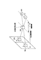
人間が自然環境にある物体に焦点を合わせるとき、その絶対距離と焦点調節には一対一の関係が存在する。眼が物体を見るときの角度である輻輳角は、物体までの絶対距離と反比例しているので、輻輳角と焦点調節もまた一対一の関係にある。したがって、輻輳角は距離感覚、もしくは焦点調整の手がかりの一つとされている。そのため、輻輳角と焦点距離の不一致は視覚への負担や疲労を引き起こすと考えられている。しかし、立体視の場合には、立体的に見ている物体から得られる距離感覚と、輻輳角との整合性が得られない。これを図2で説明する。図2において、左眼用の画像132および右眼用の画像134をそれぞれ左眼110および右眼120で見て、その画像の立体像130を見ていることを表している。右眼120および左眼110は、画像132および134に焦点を合わせているが、立体像130はその手前に見えることになり、距離感が、眼が実際に合わせている輻輳角や焦点距離と合わない。このように整合性がとれないことにより、「立体視酔い」や「VR酔い」などを生じる原因となっている。
【0006】
【発明が解決しようとする課題】
2種類の眼鏡を選択使用する方法では、作業のため両手を使用しするような場合には作業の続行が困難となる。また、近見用と遠見用のレンズを1つのレンズの中に組み込んだものでは、眼鏡レンズに対する視線の移動と視線が注視点に合致させるように補正するための頭部運動が必要となるため、意識を連続的に集中して行う作業等の場合には、しばしば作業に支障が生ずるなどの困難を伴う。
さらに、両眼立体視により3次元対象物を表示する場合などに生ずる両眼の輻輳と焦点調節との間での矛盾を解消して立体視酔いを低減させるなどの目的には適用できない。
【0007】
本発明の目的は、近見および遠見を要する作業等におけるこのような困難を軽減するために両眼での注視点までの距離を検知し、それに応じてレンズ焦点距離を自動的に調整して眼鏡の交換や意図的な視線移動および頭部運動等を行わなくとも遠見、近見の両範囲にわたり鮮明な像が観察できるように焦点調節機能を補助できる眼鏡を実現することである。
さらに両眼立体視により3次元対象物を表示する場合などに、両眼の輻輳と焦点調節との間での矛盾を緩和し、従来のステレオ視システムに比べてより自然な形態観察でき、「立体視酔い」や「VR酔い」などを著しく軽減できるステレオ視システムを実現することも本発明の目的である。
【0008】
【課題を解決するための手段】
上記の問題を解決するため、本発明においては両眼がそれぞれどの方向を向いているかを検出して両眼が注視している位置までの距離の情報を推定する手段と焦点距離を調節できるレンズ系とを備え、前記検知された注視点までの距離情報に応じて前記レンズ系の焦点距離を自動的に調節するように構成する。
【0009】
両眼がどの方向を向いているか、すなわち視線の方向が検出されれば両眼の視線が交差する点として注視する位置までの距離を推定することができる。両眼が注視する位置までの距離が分かればそれに応じて可変焦点距離レンズの焦点距離を注視点位置にある対象物が鮮明に見えるような状態に調節することができる。したがって、両眼が注視している位置にある対象物の像が常に鮮明に観察できるようにすることができる。
【0010】
また、ステレオ表示の場合には人間の視覚では注視点すなわち両眼視線が交差する位置に焦点を合わせるのが自然である。したがって、画像が表示されている位置が自然に焦点合わせして、観察できる位置からずれている分だけ補正するように可変焦点距離レンズを調節し、視覚としては自然な状態で鮮明な画像として観察できる。
【0011】
本発明によれば両眼が注視している距離に応じて、遠見用の眼鏡が必要な距離から近見用の眼鏡が必要となる範囲にわたって、眼鏡を遠見用から近見用へと交換すること無く、また、両眼の視線方向と頭部の姿勢とを意識的に変化することなく、注視点位置にある対象物の像を鮮明に観察できる。したがって、遠見用眼鏡および近見用眼鏡の両方が必要とされるような作業に際して、自然で効率の良い作業を行えるようになる。
【0012】
【発明の実施の形態】
本発明の実施形態を、図面を用いて説明する。
図3および図4は、本発明に基づいて実現される自動焦点調節眼鏡の構成の概念図である。図3に示すように、本発明の自動焦点調節眼鏡200は、左眼および右眼の視線方向検出器222および224と、焦点距離を変化できる可変焦点レンズ242および244とから構成されている。レンズ232および234は、それぞれ眼鏡の主レンズで、必要があれば、可変焦点レンズ242および244と組み合わされてレンズ系を構成している。図4は、本発明の自動焦点調節眼鏡200の制御系を示している。図4において、左眼および右眼の視線方向検出器222および224から得られた左眼および右眼の視線方向信号は、それぞれ注視点距離の算出部520へ出力する。注視点距離算出部520は、入力された視線方向信号により両眼が見ている注視点(図3の250)を算出して、眼鏡のレンズ系の焦点距離を計算する。そして、これに基づき、レンズ系の焦点距離制御部530において、可変焦点レンズ242および244への制御信号を生成する。焦点距離制御部530で生成された制御信号により、可変焦点レンズ242および244を制御し、注視点までの距離を眼鏡を構成するレンズ系の焦点距離とする。
【0013】
上述の例えば視線方向検出器等の構成要素の実現法は種々ある。したがって、本発明の実施形態は、これらの組み合わせとして実現できるのでその種類は極めて多種となる。以下ではまず、これらの構成要素ごとの実現法について述べ、それらの組み合わせとして構成される一つの実施形態について詳述することにする。
【0014】
<視線方向の検出>
図5は、注目点までの距離の算出を説明する図である。図5に示すように、注視点は、両眼眼球の向いている方向、すなわち視線方向を検知できれば、両眼の視線が交差する位置を算出して推定できる。すなわち、左眼110と右眼120と間隔をdとして、視線方向を示すそれぞれの角度をθLおよびθRとすると、眼から注目点250との距離Lは、
【数1】

【0015】
両眼の視線方向を検知する方法としては種々の眼球運動計測法が開発されており、それらが用いているものと同様の原理に基づて実現できる。しかし、本発明による自動焦点調節型眼鏡を実現するための視線方向の検知装置にはより簡便で小型軽量であることが望ましい。また、本発明による自動焦点調節型眼鏡は装着が簡便でしかも人間の動作を制限しないものであることが望ましい。したがって、本発明において採用する両眼視線検出法も非接触で小型軽量であることが望ましく、それを実現できる代表的な方法としては、まず第一に、光学的方法がある。
【0016】
<光学的方法>
光学的に両眼視線方向を検出する方法としては、瞳孔の位置を検出して視線方向を検知する方法がある。この方法によって視線方向を検出する装置も製品化されている。図6はこの方法を説明する図である。
図6(a)において、CCDカメラ等の撮像器622および624を用いて眼球部分(黒目)を画像として取り込む(図6(b)参照)。取り込んだ画像を、図6(c)に示すような画像の明暗を利用した画像処理技術を用いて、暗い部分である瞳孔部分を抽出して、その位置を検出するものである。この方法は、撮像手段が大きくなること、および撮像時間、画像処理時間などのため眼球の高速な運動を検知できないなどの改良すべき課題が残されている。
【0017】
同様な構成で、視野内にある輝点像の位置を高速に検知できる検出素子として半導体像位置検出素子(PSD)がある(例えば、特開平6−104861号公報参照)。この検出素子においては、輝点像が投射された位置において生成された光電流を分割抵抗に流入させ、その両端に設けられた電極からの出力信号を演算することによって輝点像の重心的位置を高速に得ることができる。従って、眼球の像から半導体像位置検出素子(PSD)を用いて、瞳孔部分の位置を検出することができる。
【0018】
また、PSDを改良したものとして、複眼式半導体像位置検出素子(Direction Sensitive Device:DSD)を用いた方法がある。DSDは、マイクロレンズと微少PSDとを組み合わせたものを多数配列し、微少PSDの出力が加算されて出力されるように構成されている(例えば、特開昭7−286813号公報参照)。これにより、光学系を小さくしても、等価的にレンズの開口がマイクロレンズの開口部の合計となるようにして、レンズ系を小さくすることによるS/N比の低下を回避している。瞳孔の位置検出は、前述のPSDと同様に行うことができる。
【0019】
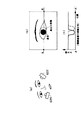
さらに、このPSD原理にしたがって視野中にある暗点像を高速に検出できる素子が、本発明の発明者により考案されている(特願平10−330362号出願参照)。この素子を用いることにより、瞳孔の暗い部分の重心的な位置を高速に検出できる。半導体暗点像検出素子を図7(a)を用いて説明する。図7(a)において、半導体暗点像検出素子900は、入射光に応じた光電流を生成する光電素子920、光電素子で生成された光電流が光投射位置に対応して流入する負荷抵抗910、負荷抵抗に流入する電流分布がほぼ一様になるように、光電流の不足分を補充するために分割抵抗940とダイオード930から構成されている。実際の構造では、光電素子920、負荷抵抗910、ダイオード930、および分割抵抗940はそれぞれ層構造を有し、全体として多層構造となっている。光電流の不足分を補充するための手段が分割抵抗940の光電素子の位置に対応した部分から供給され(図7(b)参照)、その光電流の不足分を補充する電流が分割抵抗940上の光電素子920の位置に対応した部分と両端の信号電極間の抵抗値に応じて分配される。それが補充電流供給区間全域にわたり加え合わされた電流として、分割抵抗940の両端より信号電流として出力(供給)されるように構成される。検出された信号電流を従来のPSDにおけると同じように演算処理することによって、明るい背景中の暗い像の位置を検出できる。すなわち、補充電流を供給する分割抵抗の抵抗率が一様であるとすると、抵抗値は端子との間の距離に比例するので光の入射位置xの情報(中心位置からのずれ率に相当)は次式で求められる。
【数2】
【0020】
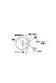
他の光学的な検出方法としては、図8に示したプルキンエ像を用いた方法がある。眼球は白目(強膜)と黒目(角膜)の部分に分かれている。角膜部分は、ガラス面と同様で透明体であり、光に対しては鏡面としての作用する。プルキンエ像とは、眼の外部にある光源(例えば、図8に示したLED820)が角膜を鏡として映されて眼球内にあるように見える輝点像のことである。図8に示されているように、眼球においては、眼球の回転中心に対して角膜表面の中心が偏心している。このため、眼球の向きが変化すると鏡に相当する面が回転し、プルキンエ像の位置が眼球の向きに対応して移動する。この移動を像位置検出器830により検出することにより、眼球の向きすなわち視線方向を検出することができる。この像位置検出器には、上述で説明した検出器(例えばPSD等)を用いることができる。
【0021】
上述のように、視線方向の検出を光学的に行うためには、瞳孔位置およびプルキンエンエ像の位置を検出して行うことができる。その他にも、白目と瞳孔境界位置や、コンタクトをはめ、それに付されたマーク位置を検知することによっても、視線方向を検出することができる。
【0022】
<筋電を検知する方法>
眼球は、眼球の周りにある筋肉を用いて動いている。図9(a)はこの眼球の周りの筋肉について示している。この眼球運動を生成する筋肉の動きは、動くと発生する皮膚電位を検出することにより検出できるので、この皮膚電位を検出することにより眼球の動きを推定することができる。図9(b)は、この皮膚電位の検出を示している。図9(b)において、眼鏡の内側に複数の電極812,814,816,817を取り付け、この電極により、その部分の皮膚電位を検出する。通常は、眼球の左右に取り付けた電極からの信号の差が、眼球の動きの向きに応じて変化する。このため、予め既知の位置を凝視して、この位置との相対的な位置を筋肉の動きを検出することで眼球の向きを推定する。
【0023】
<レンズの焦点距離を変化させる方法>
可変焦点型レンズについてもいろいろな方法がある。周知である方法としては、光学レンズの位置を変化させる方法である。本発明の自動焦点調節型眼鏡の実現には小型軽量で応答速度が速いことが望まれ、それらの点でこの方法はそれほど好ましいものではないが、この方法によって、眼鏡を構成するレンズの焦点距離変えることにより、本発明を実現できる。
【0024】
<レンズの形状を変化させる型の方法>
人間の眼球においては水晶体の厚さを変化させることによって焦点調節が行なわれている。以下においては眼球の水晶体におけると同様あるいはそれに類するような原理、すなわち、レンズ形状を変化させる型の方法による可変焦点レンズの実現法を、図10に示すことにする。
【0025】
図10において、2つの透明な板状対象物302の間に、外部環境媒体(すなわち空気)の屈折率と異なる屈折率を有する変形可能な透明体304を充満するように介在させ、2つの板状対象物302の表面形状及び変形可能な透明体304の形状をアクチュエータ306により変化させて、2つの板状対象物302を通過する光の屈折状態を変化させる。
【0026】
焦点距離を変化させるためには、例えば透明体304を液体等の流動体で構成し、そのアクチュエータ306により、流動体を密閉した板状対象物302の間に送り込むことを行えばよい。
【0027】
この図10に示した可変焦点レンズについて、特にアクチュエータ306により板状対象物等を変化させる他の方法等については、同日に出願した同じ発明者による特許出願を参照されたい。
焦点を変化させる他の方法には、例えば、圧電体で構成した板状対象物を変形させる、アクチュエータの厚みを変化させる等がある。
【0028】
<立体視への応用>
図2で示したように、両眼立体視により3次元対象物を表示する場合などに、立体が見える位置までの距離と画面までの距離が異なるため人間の目にとって焦点調節が不自然な状態、すなわち両眼の輻輳と焦点調節との間でも矛盾が生じる。このため、長時間立体視を行うと所謂「立体視酔い」とか「VR酔い」などと呼ばれる状態となりひどい場合には頭痛や吐き気をもようすことがある。このような場合に視線方向を検知し、それに応じて結果的に焦点が自然に画面上に合うように調整することにすれば、従来の立体視システムに比べてより自然な形態で、「立体視酔い」を著しく軽減できるステレオ視システムが実現される。これを図11を用いて説明する。
【0029】
図11において、図3と同様に、左眼および右眼の視線方向検出器222および224と、焦点距離を変化できる可変焦点レンズ242および244は、本発明の自動焦点調節眼鏡を構成している。レンズ232および234は、それぞれ眼鏡の主レンズで、必要があれば、可変焦点レンズ242および244と組み合わされてレンズ系を構成している。
【0030】
さて、スクリーン140上の立体視用の画像をみて立体視を行い、130にその立体画像が見えているとする。このような場合に、立体視画像130を見ている視線方向を検知し、それに応じて結果的に焦点がスクリーン140上に合うように調整する。このように眼鏡の焦点距離を調節して、眼の焦点が立体視画像130に合わせられていても、実際に見る必要のあるスクリーン140上に焦点を合わせることができる。これにより、両眼の輻輳と焦点調節との間の矛盾による「立体視酔い」を著しく軽減できる。
【0031】
【発明の効果】
上記の説明のように、本発明においては、人間が見ようとする距離にある対象物に容易に焦点を合わせられる様に、焦点調節可能なレンズ系の焦点距離を注視点距離に応じて変化させることができる。
【0032】
そのため、たとえばオフィスにおける事務作業や工業における組立作業等の様に、腕が届く程度の範囲での作業において、近い対象物および離れた対象物を明瞭に観察し判断して操作するような場合に、老眼の人でも眼鏡を掛け替える必要がなく、作業効率を著しく高めることができる。
さらに、両眼立体視により3次元対象物を表示する場合に、長時間立体視を行うと生じる所謂「立体視酔い」とか「VR酔い」を防ぐためも使用することができる。
【図面の簡単な説明】
【図1】眼において、老眼鏡が必要となることを説明する図である。
【図2】立体視において、「立体視酔い」が起きる原因を説明する図である。
【図3】本発明の自動焦点調節眼鏡の構成を説明する図である。
【図4】本発明の自動焦点調節眼鏡の制御系を説明するブロック図である。
【図5】視線方向から焦点距離を算出することを説明する図である。
【図6】PSD等による眼の位置検出を説明する図である。
【図7】半導体暗点像検出素子による眼の位置検出を説明する図である。
【図8】プルキンエ像による視線方向検出を説明する図である。
【図9】皮膚電位により視線方向検出を説明する図である。
【図10】可変焦点レンズの構成を説明する図である。
【図11】立体視への応用を説明する図である。
【符号の説明】
110 左眼
120 右眼
130 立体視画像
132 左眼用画像
134 右眼用画像
140 スクリーン
200 自動焦点調節眼鏡
222,224 視線方向検出器
232,234 レンズ
242,244 可変焦点レンズ
250 注目点
302 板状対象物
304 透明体
306 アクチュエータ
520 算出部
520 注視点距離算出部
530 焦点距離制御部
622,624 画像撮像器
812,814,816,817 電極
830 像位置検出器
900 半導体暗点像検出素子
910 負荷抵抗
920 光電素子
930 ダイオード
940 分割抵抗[0001]
BACKGROUND OF THE INVENTION
The present invention relates to automatic focusing glasses capable of changing a focal length according to a gaze point distance.
[0002]
[Background]
In the human eyeball, the thickness of the crystalline lens changes according to the distance of the object to be watched, and a clear image is projected on the retina (FIG. 1 (a) I). However, in the case of hyperopia (FIG. 1 (a) II) or myopia (FIG. 1 (a) III), an image cannot be projected on the retina.
[0003]
In addition, the adjustable range of the lens thickness becomes narrower with age. For this reason, the distance of the object to be seen in daily life often exceeds the focus adjustable range, making various operations difficult. Glasses are used to compensate for the focus adjustment ability of the eyeball (see FIG. 1B).
[0004]
When a nearsighted person becomes old and the focus adjustment range is narrowed, a method of selectively using two types of glasses for near vision and far vision is used. In addition, the upper region of the spectacle lens is used for far vision and the lower region is used for near vision, with different lens focal lengths in one lens. This method is used to change the distance and for near vision and for near vision.
[0005]
When a human focuses on an object in the natural environment, there is a one-to-one relationship between absolute distance and focus adjustment. Convergence angle is an angle when the eye looks at an object is, since the absolute distance and inversely proportional to the object, the angle of convergence and focusing is also in one-to-one relationship. Therefore, the convergence angle is one of the cues for distance sense or focus adjustment. For this reason, it is considered that the mismatch between the angle of convergence and the focal length causes visual burden and fatigue. However, in the case of stereoscopic viewing, the consistency between the sense of distance obtained from an object viewed stereoscopically and the convergence angle cannot be obtained. This will be described with reference to FIG. In FIG. 2, the
[0006]
[Problems to be solved by the invention]
In the method of selectively using two kinds of glasses, it is difficult to continue the work when both hands are used for the work. In addition, in the case where the near vision lens and the far vision lens are incorporated in one lens, the movement of the line of sight with respect to the spectacle lens and the head movement for correcting the line of sight to match the gaze point are required. In the case of work that is carried out by concentrating consciousness continuously, it is often accompanied by difficulties such as trouble in the work.
Furthermore, it cannot be applied to the purpose of reducing stereoscopic sickness by eliminating the contradiction between binocular convergence and focus adjustment that occurs when a three-dimensional object is displayed by binocular stereoscopic vision.
[0007]
The object of the present invention is to detect the distance to the gazing point with both eyes in order to alleviate such difficulties in work that requires near vision and far vision, and automatically adjust the lens focal length accordingly. An object of the present invention is to realize a spectacle that can assist a focus adjustment function so that a clear image can be observed over both the distance and near vision ranges without performing eyeglass exchange, intentional line-of-sight movement, and head movement.
Furthermore, when displaying a three-dimensional object by binocular stereoscopic vision, etc., the contradiction between binocular convergence and focus adjustment can be alleviated, and more natural morphological observation can be performed compared to conventional stereo vision systems. It is also an object of the present invention to realize a stereo vision system that can remarkably reduce “stereoscopic sickness” and “VR sickness”.
[0008]
[Means for Solving the Problems]
In order to solve the above problem, in the present invention, means for detecting which direction each eye is facing and estimating information on the distance to the position where both eyes are gazing and a lens capable of adjusting the focal length And a focal length of the lens system is automatically adjusted according to the detected distance information to the gazing point.
[0009]
If the direction in which both eyes are facing, that is, the direction of the line of sight is detected, the distance to the position where the eyes are observed as the point where the lines of sight of both eyes intersect can be estimated. If the distance to the position where both eyes are gazing is known, the focal length of the variable focal length lens can be adjusted accordingly so that the object at the gazing point position can be seen clearly. Therefore, it is possible to always clearly observe the image of the object at the position where both eyes are gazing.
[0010]
In the case of stereo display, it is natural for human vision to focus on the point of sight, that is, the position where the binocular line of sight intersects. Therefore, the variable focal length lens is adjusted so that the position where the image is displayed is naturally focused and the amount of deviation from the observable position is corrected, and the image is observed as a clear image in a natural state. it can.
[0011]
According to the present invention, according to the distance at which both eyes are gazing, the spectacles are exchanged from the far vision to the near vision over the range where the near vision glasses are necessary to the near vision glasses. In addition, it is possible to clearly observe the image of the object at the position of the gazing point without intentionally changing the line-of-sight direction of both eyes and the posture of the head. Therefore, it is possible to perform a natural and efficient work when the work requires both the far vision glasses and the near vision glasses.
[0012]
DETAILED DESCRIPTION OF THE INVENTION
Embodiments of the present invention will be described with reference to the drawings.
FIG. 3 and FIG. 4 are conceptual diagrams of the configuration of the automatic focusing glasses realized based on the present invention. As shown in FIG. 3, the automatic focusing
[0013]
There are various methods for realizing the above-described components such as the gaze direction detector. Therefore, since the embodiment of the present invention can be realized as a combination of these, the types thereof are extremely various. In the following, first, an implementation method for each of these components will be described, and one embodiment configured as a combination thereof will be described in detail.
[0014]
<Gaze direction detection>
FIG. 5 is a diagram for explaining the calculation of the distance to the point of interest. As shown in FIG. 5, the gaze point can be estimated by calculating the position where the line of sight of both eyes intersects if the direction in which the binocular eyeballs face, that is, the line of sight direction can be detected. That is, when the distance between the
[Expression 1]
[0015]
Various eye movement measurement methods have been developed as methods for detecting the line-of-sight direction of both eyes, and can be realized based on the same principle as those used. However, it is desirable that the gaze direction detecting device for realizing the autofocusing glasses according to the present invention be simpler, smaller and lighter. In addition, it is desirable that the auto-focusing glasses according to the present invention are easy to wear and do not restrict human movement. Therefore, it is desirable that the binocular line-of-sight detection method employed in the present invention is also non-contact, small and light, and a representative method capable of realizing it is, first of all, an optical method.
[0016]
<Optical method>
As a method for optically detecting the binocular line-of-sight direction, there is a method for detecting the line-of-sight direction by detecting the position of the pupil. Devices that detect the line-of-sight direction by this method have also been commercialized. FIG. 6 is a diagram for explaining this method.
In FIG. 6A, an eyeball portion (black eye) is captured as an
[0017]
There is a semiconductor image position detecting element (PSD) as a detecting element capable of detecting the position of a bright spot image in the field of view at high speed with the same configuration (see, for example, Japanese Patent Laid-Open No. 6-104861). In this detection element, the photocurrent generated at the position where the bright spot image is projected flows into the dividing resistor, and the output signal from the electrodes provided at both ends thereof is calculated, thereby calculating the barycentric position of the bright spot image. Can be obtained at high speed. Therefore, the position of the pupil portion can be detected from the image of the eyeball using the semiconductor image position detecting element (PSD).
[0018]
Further, as an improvement of PSD, there is a method using a compound eye type semiconductor image position detection element (Direction Sensitive Device (DSD)). The DSD is configured so that a large number of combinations of microlenses and micro PSDs are arranged and the outputs of micro PSDs are added and output (for example, see Japanese Patent Application Laid-Open No. 7-286813). As a result, even if the optical system is made smaller, the lens aperture is equivalently the sum of the apertures of the microlens, so that a reduction in the S / N ratio due to the smaller lens system is avoided. The detection of the position of the pupil can be performed in the same manner as the PSD described above.
[0019]
Furthermore, an element capable of detecting a dark spot image in the visual field at high speed according to the PSD principle has been devised by the inventor of the present invention (see Japanese Patent Application No. 10-330362). By using this element, the center-of-gravity position of the dark part of the pupil can be detected at high speed. The semiconductor dark spot image detection element will be described with reference to FIG. In FIG. 7A, a semiconductor dark spot
[Expression 2]
[0020]
As another optical detection method, there is a method using the Purkinje image shown in FIG. The eyeball is divided into white eyes (sclera) and black eyes (cornea). The cornea portion is a transparent body similar to the glass surface, and acts as a mirror surface for light. The Purkinje image is a bright spot image in which a light source (for example,
[0021]
As described above, in order to optically detect the line-of-sight direction, the pupil position and the position of the Purkinje image can be detected. In addition, the line-of-sight direction can also be detected by detecting a boundary position between the white eye and the pupil, a contact, and a mark position attached thereto.
[0022]
<Method for detecting myoelectricity>
The eyeball moves using muscles around the eyeball. FIG. 9A shows the muscles around the eyeball. Since the movement of the muscle that generates the eye movement can be detected by detecting the skin potential generated when the eye moves, the movement of the eye can be estimated by detecting the skin potential. FIG. 9B shows the detection of this skin potential. In FIG. 9B, a plurality of
[0023]
<Method of changing the focal length of the lens>
There are various methods for variable focus lenses. A well-known method is a method of changing the position of the optical lens. In order to realize the auto-focusing glasses of the present invention, it is desired that the glasses are small and light, and the response speed is high. In this respect, this method is not so preferable. By changing, the present invention can be realized.
[0024]
<Method of mold to change lens shape>
In the human eyeball, focus adjustment is performed by changing the thickness of the crystalline lens. In the following, the principle similar to or similar to that in the crystalline lens of the eyeball, that is, a method for realizing a variable focus lens by a method of changing the lens shape will be shown in FIG.
[0025]
In FIG. 10, two plates are interposed between two transparent plate-like objects 302 so as to be filled with a deformable transparent body 304 having a refractive index different from that of the external environment medium (ie, air). The surface shape of the object 302 and the shape of the deformable transparent body 304 are changed by the
[0026]
In order to change the focal length, for example, the transparent body 304 may be formed of a fluid such as a liquid, and the fluid may be fed between the sealed plate-like objects 302 by the
[0027]
Regarding the variable focus lens shown in FIG. 10, in particular, for other methods for changing the plate-like object or the like by the
Other methods for changing the focus include, for example, deforming a plate-like object formed of a piezoelectric body, changing the thickness of an actuator, and the like.
[0028]
<Application to stereoscopic vision>
As shown in FIG. 2, when displaying a three-dimensional object by binocular stereoscopic vision, the focus adjustment is unnatural for the human eye because the distance to the position where the stereoscopic can be seen and the distance to the screen are different. That is, there is also a contradiction between binocular convergence and focus adjustment. For this reason, when stereoscopic vision is performed for a long time, a so-called “stereoscopic sickness” or “VR sickness” occurs, and in severe cases, headache or nausea may occur. In such a case, if the gaze direction is detected and the focus is adjusted so that the focus is naturally adjusted on the screen as a result, the “stereoscopic” has a more natural form compared to the conventional stereoscopic system. A stereo vision system that can significantly reduce “visual sickness” is realized. This will be described with reference to FIG.
[0029]
In FIG. 11, as with FIG. 3, the left-eye and right-eye
[0030]
Now, it is assumed that the stereoscopic image on the
[0031]
【The invention's effect】
As described above, in the present invention, the focal length of the lens system that can be adjusted is changed in accordance with the gaze point distance so that an object at a distance to be seen by a human can be easily focused. be able to.
[0032]
For this reason, when working within a range where the arm can reach, such as office work in the office or assembly work in industry, etc., when a close object and a distant object are clearly observed, judged and operated. Even presbyopic people do not need to change their glasses, and work efficiency can be significantly increased.
Furthermore, when displaying a three-dimensional object by binocular stereoscopic vision, it can also be used to prevent so-called “stereoscopic sickness” or “VR sickness” that occurs when stereoscopic vision is performed for a long time.
[Brief description of the drawings]
FIG. 1 is a diagram for explaining that reading glasses are necessary for eyes.
FIG. 2 is a diagram for explaining the cause of “stereoscopic sickness” in stereoscopic vision;
FIG. 3 is a diagram illustrating a configuration of automatic focusing glasses according to the present invention.
FIG. 4 is a block diagram illustrating a control system of the automatic focusing glasses according to the present invention.
FIG. 5 is a diagram for explaining calculation of a focal length from a line-of-sight direction.
FIG. 6 is a diagram for explaining eye position detection by PSD or the like.
FIG. 7 is a diagram for explaining eye position detection by a semiconductor dark spot image detection element;
FIG. 8 is a diagram for explaining gaze direction detection based on a Purkinje image.
FIG. 9 is a diagram illustrating gaze direction detection based on skin potential.
FIG. 10 is a diagram illustrating a configuration of a variable focus lens.
FIG. 11 is a diagram illustrating application to stereoscopic vision.
[Explanation of symbols]
110
Claims (2)
焦点距離を調節できるレンズと、
前記検知された距離情報に基づいて、前記レンズ系の焦点距離を調節する焦点距離調節手段とを備え、
前記半導体暗点像検出素子は、光が入射された部分で入射された光の強度に応じた光電流を生成する光電素子と、前記光電素子において生成された前記光電流が前記光の入射位置に対応して流入する負荷抵抗と、前記光の入射位置に対応した前記負荷抵抗へ流入する電流の分布が検出範囲全体にわたりほぼ一様になるように前記光電流の不足分の電流を補充流入させるための、前記光電素子に対応して配設された分割抵抗及びダイオードと、前記分割抵抗の両端に配設された信号電極端とを有し、前記光電流の不足分を補充するための電流が、前記分割抵抗の前記光電流が前記負荷抵抗へ流入する位置に対応した部分から供給され、前記光電流の不足分を補充するための電流が、前記分割抵抗上の前記光電流の不足分を補充するための電流の供給部分と前記信号電極端との間の抵抗値に応じた割合で分配され、前記光電流の不足分を補充するための電流の供給区間全域にわたり加え合わされた電流として信号電極端から出力される
ことを特徴とする自動焦点調節型眼鏡。Means for detecting the position of the eyes of both eyes by detecting the position of the eyes of both eyes, using a semiconductor dark spot image detecting element that detects a dark portion against a bright background, and a distance to a position to be watched with both eyes;
A lens with adjustable focal length,
A focal length adjusting means for adjusting a focal length of the lens system based on the detected distance information;
The semiconductor dark point image detection element, a photoelectric element which light to generate a photocurrent corresponding to the intensity of incident light at the incident portion, the incident position the photocurrent generated is the light at the photoelectric elements replenishment inflow load resistor flowing correspondingly, the shortage of current in the photocurrent as the distribution of current flowing to the load resistance corresponding to the incident position of the light is substantially uniform over the entire detection range A split resistor and a diode disposed corresponding to the photoelectric element , and signal electrode ends disposed at both ends of the split resistor, for supplementing the shortage of the photocurrent A current is supplied from a portion of the dividing resistor corresponding to a position where the photocurrent flows into the load resistor, and a current for supplementing the shortage of the photocurrent is insufficient for the photocurrent on the dividing resistor. Of current to replenish the minute Are distributed at a ratio corresponding to the resistance value between the signal electrode terminal and feeding portion, is outputted from the signal electrode end as added combined current over supply interval entire current to replenish the shortage of the photocurrent This is an automatic focusing type eyeglass.
前記焦点距離が調整できるレンズは、2つの透明な板状対象物間に外部環境媒体の屈折率と異なる屈折率を有する変形可能な透明体を充満するように介在させ、該板状対象物周辺に設けたアクチュエータの厚みを変化させることにより、2つの板状対象物の表面形状及び変形可能な透明体形状を変化させて、2つの板状対象物を通過する光の屈折状態を変化させる可変焦点レンズであることを特徴とする自動焦点調節型眼鏡。In the automatic focusing glasses according to claim 1,
The lens capable of adjusting the focal length is interposed between two transparent plate-like objects so as to be filled with a deformable transparent body having a refractive index different from the refractive index of the external environment medium. By changing the thickness of the actuator provided on the surface, the surface shape of the two plate-like objects and the deformable transparent body shape are changed to change the refractive state of the light passing through the two plate-like objects. An auto-focusing spectacle that is a focusing lens.
Priority Applications (1)
| Application Number | Priority Date | Filing Date | Title |
|---|---|---|---|
| JP5483699A JP3624112B2 (en) | 1999-03-02 | 1999-03-02 | Auto focus glasses |
Applications Claiming Priority (1)
| Application Number | Priority Date | Filing Date | Title |
|---|---|---|---|
| JP5483699A JP3624112B2 (en) | 1999-03-02 | 1999-03-02 | Auto focus glasses |
Publications (2)
| Publication Number | Publication Date |
|---|---|
| JP2000249902A JP2000249902A (en) | 2000-09-14 |
| JP3624112B2 true JP3624112B2 (en) | 2005-03-02 |
Family
ID=12981728
Family Applications (1)
| Application Number | Title | Priority Date | Filing Date |
|---|---|---|---|
| JP5483699A Expired - Fee Related JP3624112B2 (en) | 1999-03-02 | 1999-03-02 | Auto focus glasses |
Country Status (1)
| Country | Link |
|---|---|
| JP (1) | JP3624112B2 (en) |
Cited By (1)
| Publication number | Priority date | Publication date | Assignee | Title |
|---|---|---|---|---|
| CN102937745A (en) * | 2012-11-13 | 2013-02-20 | 京东方科技集团股份有限公司 | Open-type head-wearing display device and display method thereof |
Families Citing this family (14)
| Publication number | Priority date | Publication date | Assignee | Title |
|---|---|---|---|---|
| EP2315448B1 (en) * | 2004-01-26 | 2018-03-07 | DigitalOptics Corporation | Thin camera having sub-pixel resolution |
| JP5246666B2 (en) * | 2009-05-11 | 2013-07-24 | パナソニック株式会社 | Multifocal electronic glasses |
| KR101077432B1 (en) | 2010-05-07 | 2011-10-26 | 엘지이노텍 주식회사 | 3D glasses device, 3D image display system and driving method thereof |
| GB201310658D0 (en) * | 2013-06-14 | 2013-07-31 | Adlens Ltd | Focal length adjustment |
| JP2015052772A (en) * | 2013-08-06 | 2015-03-19 | 孝郎 林 | Eyesight correction device |
| WO2016067433A1 (en) * | 2014-10-30 | 2016-05-06 | 株式会社ニコン | Lens system and contact lens |
| JP6682456B2 (en) | 2015-02-03 | 2020-04-15 | 株式会社ジンズホールディングス | Focus adjustment auxiliary lens |
| EP3440497B1 (en) | 2016-04-08 | 2023-08-16 | Magic Leap, Inc. | Augmented reality systems and methods with variable focus lens elements |
| JP7026925B2 (en) | 2017-06-13 | 2022-03-01 | 株式会社エルシオ | glasses |
| US11733516B2 (en) | 2017-10-11 | 2023-08-22 | Magic Leap, Inc. | Augmented reality display comprising eyepiece having a transparent emissive display |
| US10867174B2 (en) | 2018-02-05 | 2020-12-15 | Samsung Electronics Co., Ltd. | System and method for tracking a focal point for a head mounted device |
| JP7703867B2 (en) | 2021-03-12 | 2025-07-08 | 株式会社Jvcケンウッド | Automatic focus adjustment glasses, method and program for controlling automatic focus adjustment glasses |
| JP2023006126A (en) * | 2021-06-30 | 2023-01-18 | ViXion株式会社 | Lense controller, spectacle lens device, glasses, method for control, and program |
| CN114280778A (en) * | 2021-11-24 | 2022-04-05 | 歌尔光学科技有限公司 | A kind of smart glasses and its image distance adjustment method |
-
1999
- 1999-03-02 JP JP5483699A patent/JP3624112B2/en not_active Expired - Fee Related
Cited By (2)
| Publication number | Priority date | Publication date | Assignee | Title |
|---|---|---|---|---|
| CN102937745A (en) * | 2012-11-13 | 2013-02-20 | 京东方科技集团股份有限公司 | Open-type head-wearing display device and display method thereof |
| CN102937745B (en) * | 2012-11-13 | 2015-04-01 | 京东方科技集团股份有限公司 | Open-type head-wearing display device and display method thereof |
Also Published As
| Publication number | Publication date |
|---|---|
| JP2000249902A (en) | 2000-09-14 |
Similar Documents
| Publication | Publication Date | Title |
|---|---|---|
| JP3624112B2 (en) | Auto focus glasses | |
| US5777715A (en) | Low vision rehabilitation system | |
| US10426668B2 (en) | Binocular display apparatus | |
| EP0509090B1 (en) | Head mounted video display | |
| US5861936A (en) | Regulating focus in accordance with relationship of features of a person's eyes | |
| US4923296A (en) | Oriented simultaneous vision bifocal contact lenses or the like utilizing introaocular suppression of blur | |
| US5724163A (en) | Optical system for alternative or simultaneous direction of light originating from two scenes to the eye of a viewer | |
| CN110850594B (en) | Head-mounted visual equipment and eyeball tracking system for same | |
| JPWO2016203654A1 (en) | Head mounted display device and visual assistance method using the same | |
| JPWO2018003205A1 (en) | Glasses with video display function | |
| US20260016707A1 (en) | Eyeglass devices and related methods | |
| JP2001290101A (en) | Depth direction viewpoint adjustment intention detection and will drive method and automatic perspective correction glasses | |
| JP3698582B2 (en) | Image display device | |
| WO2016002296A1 (en) | Optical control device and optical control method | |
| JP2998233B2 (en) | Variable focus glasses | |
| KR101817436B1 (en) | Apparatus and method for displaying contents using electrooculogram sensors | |
| JP2017037235A (en) | Binoculars display device | |
| JP2005286927A (en) | Transparent indicating device mounted on the head | |
| JP7753000B2 (en) | Video display device and control method thereof | |
| CN104076515A (en) | Head-mounted displayer conveniently used by ametropia patient | |
| CN204374515U (en) | A kind of head mounted display be convenient to ametropia patient and used | |
| WO2023023398A1 (en) | Eyeglass devices and related methods | |
| JPH10179520A (en) | Gaze detection method and apparatus, and storage medium | |
| CN120577970B (en) | Method for realizing near object display and AR display equipment | |
| JP7485426B1 (en) | Head-mounted imaging device and line-of-sight image adjustment method |
Legal Events
| Date | Code | Title | Description |
|---|---|---|---|
| RD03 | Notification of appointment of power of attorney |
Effective date: 20031210 Free format text: JAPANESE INTERMEDIATE CODE: A7423 |
|
| A977 | Report on retrieval |
Effective date: 20040123 Free format text: JAPANESE INTERMEDIATE CODE: A971007 |
|
| A131 | Notification of reasons for refusal |
Effective date: 20040316 Free format text: JAPANESE INTERMEDIATE CODE: A131 |
|
| A521 | Written amendment |
Free format text: JAPANESE INTERMEDIATE CODE: A523 Effective date: 20040514 |
|
| A02 | Decision of refusal |
Free format text: JAPANESE INTERMEDIATE CODE: A02 Effective date: 20040629 |
|
| A521 | Written amendment |
Free format text: JAPANESE INTERMEDIATE CODE: A523 Effective date: 20040824 |
|
| A911 | Transfer of reconsideration by examiner before appeal (zenchi) |
Free format text: JAPANESE INTERMEDIATE CODE: A911 Effective date: 20040916 |
|
| TRDD | Decision of grant or rejection written | ||
| A01 | Written decision to grant a patent or to grant a registration (utility model) |
Free format text: JAPANESE INTERMEDIATE CODE: A01 Effective date: 20041116 |
|
| A61 | First payment of annual fees (during grant procedure) |
Free format text: JAPANESE INTERMEDIATE CODE: A61 Effective date: 20041129 |
|
| R150 | Certificate of patent (=grant) or registration of utility model |
Free format text: JAPANESE INTERMEDIATE CODE: R150 |
|
| FPAY | Renewal fee payment (prs date is renewal date of database) |
Free format text: PAYMENT UNTIL: 20081203 Year of fee payment: 4 |
|
| FPAY | Renewal fee payment (prs date is renewal date of database) |
Free format text: PAYMENT UNTIL: 20091203 Year of fee payment: 5 |
|
| LAPS | Cancellation because of no payment of annual fees |