JP3633232B2 - Electric motor - Google Patents
Electric motor Download PDFInfo
- Publication number
- JP3633232B2 JP3633232B2 JP26152797A JP26152797A JP3633232B2 JP 3633232 B2 JP3633232 B2 JP 3633232B2 JP 26152797 A JP26152797 A JP 26152797A JP 26152797 A JP26152797 A JP 26152797A JP 3633232 B2 JP3633232 B2 JP 3633232B2
- Authority
- JP
- Japan
- Prior art keywords
- rotor
- coil
- outer peripheral
- peripheral edge
- motor
- Prior art date
- Legal status (The legal status is an assumption and is not a legal conclusion. Google has not performed a legal analysis and makes no representation as to the accuracy of the status listed.)
- Expired - Lifetime
Links
- 230000002093 peripheral effect Effects 0.000 claims description 43
- 230000006698 induction Effects 0.000 description 12
- 230000001360 synchronised effect Effects 0.000 description 10
- 230000004907 flux Effects 0.000 description 6
- RYGMFSIKBFXOCR-UHFFFAOYSA-N Copper Chemical compound [Cu] RYGMFSIKBFXOCR-UHFFFAOYSA-N 0.000 description 5
- 229910052802 copper Inorganic materials 0.000 description 5
- 239000010949 copper Substances 0.000 description 5
- 239000011295 pitch Substances 0.000 description 4
- 230000001629 suppression Effects 0.000 description 4
- 229910000831 Steel Inorganic materials 0.000 description 3
- 238000010586 diagram Methods 0.000 description 3
- 229910052751 metal Inorganic materials 0.000 description 3
- 239000002184 metal Substances 0.000 description 3
- 239000010959 steel Substances 0.000 description 3
- 229910052782 aluminium Inorganic materials 0.000 description 2
- XAGFODPZIPBFFR-UHFFFAOYSA-N aluminium Chemical compound [Al] XAGFODPZIPBFFR-UHFFFAOYSA-N 0.000 description 2
- 238000010030 laminating Methods 0.000 description 2
- 230000000694 effects Effects 0.000 description 1
- 238000004804 winding Methods 0.000 description 1
Images


Landscapes
- Permanent Magnet Type Synchronous Machine (AREA)
- Permanent Field Magnets Of Synchronous Machinery (AREA)
- Induction Machinery (AREA)
- Insulation, Fastening Of Motor, Generator Windings (AREA)
- Synchronous Machinery (AREA)
Description
【0001】
【発明の属する技術分野】
本発明は、電動機に関するものである。
【0002】
【従来の技術】
従来、電動機は、ロータ、及び該ロータの周囲に配設されたステータを有し、該ステータは、ステータコア、及び該ステータコアに巻装されたステータコイルから成る。そして、該ステータコイルに電流を供給し、回転磁界が形成されると、ロータが回転するようになっている。
【0003】
また、ロータに永久磁石を配設することによって磁極が形成された同期式の電動機においては、電磁鋼板を積層して形成されたコアの複数箇所に永久磁石を配設するようになっている。
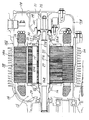
図2は従来の同期式の電動機の要部断面図である。
図において、14はモータケースであり、該モータケース14内に同期式の電動機15が収容される。前記モータケース14は、円筒状部分14a、及び該円筒状部分14aの一端を閉鎖して、密閉されたモータ収容室18を形成する蓋(ふた)部分14bから成る。また、前記円筒状部分14aの外周面には複数のフィン24が形成される。
【0004】
そして、前記円筒状部分14aの底部の中央、及び蓋部分14bの中央にはそれぞれ穴が形成され、該穴を貫通させてモータシャフト27が配設され、該モータシャフト27はベアリング29、30によって回転自在に支持される。また、前記蓋部分14bの穴に隣接させて凹部14cが形成され、該凹部14cを蓋部材33によって閉鎖することによりセンサ室34が形成される。
【0005】
そして、該センサ室34にはレゾルバ35が配設され、該レゾルバ35は、前記モータシャフト27の回転に基づいて電動機15の磁極の位置を検出する。
前記電動機15は、前記モータシャフト27の軸方向におけるほぼ中央に取り付けられ、該モータシャフト27と共に回転させられるロータ37、及び前記円筒状部分14aの円筒部の内周面において前記ロータ37と対向させて固定されたステータ38を有し、該ステータ38はステータコア38a、及び該ステータコア38aに巻装された3相(U相、V相及びW相)のコイル39から成る。
【0006】
したがって、該各コイル39に図示しないインバータにおいて発生させられた3相の交流電流を供給することによって、ロータ37を回転させることができる。
該ロータ37は、複数の電磁鋼板を積層して形成されたコア17、及び該コア17の複数箇所に配設された永久磁石55を有し、前記コア17の外周部分に、円周方向における複数箇所に等ピッチで前記永久磁石55が配設される。該永久磁石55は、両端に配設されたエンドプレート56、57によって押さえられた状態で固定され、電動機15の磁極を形成する。そのために、前記モータシャフト27の外周面にスプライン27aが、ロータ37の内周面にスプライン37aが、エンドプレート56、57の内周面にスプライン56a、57aがそれぞれ形成され、前記モータシャフト27とロータ37及びエンドプレート56、57とをスプライン係合させることができるようになっている。
【0007】
また、前記モータシャフト27の外周面には、前記ベアリング30に隣接させて係止凸部27bが形成される。したがって、該係止凸部27bにエンドプレート57を押し付けて前記エンドプレート57、ロータ37及びエンドプレート56を順にモータシャフト27にセットし、止めナット16をモータシャフト27の所定箇所に螺(ら)合させることによって、ロータ37をモータシャフト27に対して位置決めし、かつ、固定することができる。
【0008】
前記エンドプレート56、57は、ロータ37に対応する環状の形状を有し、かつ、外周縁がロータ37の外周縁よりわずかに内方になるような径方向寸法を有する。したがって、前記エンドプレート56、57によってロータ37及び永久磁石55の端面を押さえるとともに、覆うことができるので、前記ロータ37が軸方向に移動するのを防止することができるとともに、永久磁石55が破損したときに磁石片が周囲に飛散するのを防止することができる。
【0009】
一方、ロータとしてかご形回転子を使用する誘導式の電動機においては、ロータの円周方向における複数箇所に配設された銅製の棒の両端を短絡環によって連結するようにしている。
図3は従来の誘導式の電動機のロータの概略図である。
図において、101はロータ、102はモータシャフト、103は前記ロータ101の外周部分において、円周方向における複数箇所に等ピッチで配設された銅製の棒、104は該各棒103の両端を連結するアルミニウム製の短絡環である。
【0010】
【発明が解決しようとする課題】
しかしながら、前記従来の電動機においては、同期式の電動機15(図2)の場合、前記エンドプレート56、57によってロータ37及び永久磁石55の端面を覆うために、エンドプレート56、57は、外周縁がロータ37の外周縁よりわずかに内方になるような径方向寸法を有するので、エンドプレート56、57の外周縁が前記コイル39のコイルエンドに近接してしまう。
【0011】
また、前記エンドプレート56、57は、通常、非磁性の金属によって形成される。したがって、前記コイル39に交流電流を供給すると、該交流電流に含まれる高周波成分によって、又は交流電流に伴って発生する誘導起電力によって、エンドプレート56、57に渦電流が発生し、電動機15の効率を低くしてしまう。
【0012】
そして、誘導式の電動機の場合、ロータ101における棒103の両端部分に短絡環104が配設され、該短絡環104は、通常、非磁性の金属によって形成されるので、ロータ101の回転に伴って短絡環104に渦電流が発生し、電動機の効率を低くしてしまう。
本発明は、前記従来の電動機の問題点を解決して、渦電流が発生するのを抑制し、効率を高くすることができる電動機を提供することを目的とする。
【0013】
【課題を解決するための手段】
そのために、本発明の電動機においては、コアの円周方向における複数箇所に永久磁石が配設されたロータと、該ロータと所定の間隔を置いて配設されたステータと、該ステータに巻装されたコイルとを備える。
そして、前記永久磁石の両端を押さえた状態で固定し、かつ、ロータ及び永久磁石の端面を覆うエンドプレートを有する。
【0014】
また、該エンドプレートは、前記端面と軸方向において反対側の部分に形成された段部を備え、前記端面を覆わない部分の外周縁とコイルの内周縁との間のエアギャップが大きくされ、前記端面を覆う部分の外周縁が前記端面を覆わない部分の外周縁よりコイルエンドと近接させて配設される。
【0017】
【発明の実施の形態】
以下、本発明の実施の形態について図面を参照しながら詳細に説明する。
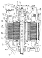
図1は本発明の第1の実施の形態における同期式の電動機の要部断面図である。
図において、14はモータケースであり、該モータケース内に同期式の電動機15が収容される。前記モータケース14は、円筒状部分14a、及び該円筒状部分14aの一端を閉鎖して、密閉されたモータ収容室18を形成する蓋部分14bから成る。また、前記円筒状部分14aの外周面には複数のフィン24が形成される。
【0018】
そして、前記円筒状部分14aの底部の中央、及び蓋部分14bの中央にはそれぞれ穴が形成され、該穴を貫通させてモータシャフト27が配設され、該モータシャフト27はベアリング29、30によって回転自在に支持される。また、前記蓋部分14bの穴に隣接させて凹部14cが形成され、該凹部14cを蓋部材33によって閉鎖することによりセンサ室34が形成される。
【0019】
そして、該センサ室34にはレゾルバ35が配設され、該レゾルバ35は、前記モータシャフト27の回転に基づいて電動機15の磁極の位置を検出する。
前記電動機15は、前記モータシャフト27の軸方向におけるほぼ中央に取り付けられ、該モータシャフト27と共に回転させられるロータ37、及び前記円筒状部分14aの円筒部の内周面において前記ロータ37と対向させて、かつ、ロータ37との間に所定の間隔を置いて配設されたステータ38を有し、該ステータ38はステータコア38a、及び該ステータコア38aに巻装された3相(U相、V相及びW相)のコイル139から成る。
【0020】
したがって、該各コイル139に図示しないインバータにおいて発生させられた3相の交流電流を供給することによって、ロータ37を回転させることができる。
該ロータ37は、複数の電磁鋼板を積層して形成されたコア17、及び該コア17の複数箇所に配設された永久磁石55を有し、前記コア17の外周部分に、円周方向における複数箇所に等ピッチで前記永久磁石55が配設される。該永久磁石55は、両端に配設された端部部材としてのエンドプレート156、157によって押さえられた状態で固定され、電動機15の磁極を形成する。そのために、前記モータシャフト27の外周面にスプライン27aが、ロータ37の内周面にスプライン37aが、エンドプレート156、157の内周面にスプライン56a、57aがそれぞれ形成され、前記モータシャフト27とロータ37及びエンドプレート156、157とをスプライン係合させることができるようになっている。
【0021】
また、前記モータシャフト27の外周面には、前記ベアリング30に隣接させて係止凸部27bが形成される。したがって、該係止凸部27bにエンドプレート157を押し付けて前記エンドプレート157、ロータ37及びエンドプレート156を順にモータシャフト27にセットし、止めナット16をモータシャフト27の所定箇所に螺合させることによって、ロータ37をモータシャフト27に対して位置決めし、かつ、固定することができる。
【0022】
前記エンドプレート156、157は、ロータ37に対応する環状の形状を有し、かつ、外周縁がロータ37の外周縁よりわずかに内方になるような径方向寸法を有する。したがって、前記エンドプレート156、157によってロータ37及び永久磁石55の端面を押さえるとともに、覆うことができるので、前記ロータ37が軸方向に移動するのを防止することができるとともに、永久磁石55が破損したときに磁石片が周囲に飛散するのを防止することができる。
【0023】
ところで、前記エンドプレート156、157によってロータ37及び永久磁石55の端面を覆うために、前記エンドプレート156、157は、外周縁がロータ37の外周縁よりわずかに内方になるような径方向寸法を有するので、エンドプレート156、157の外周縁が前記コイル139のコイルエンドに近接してしまう。そして、前記エンドプレート156、157は、通常、非磁性の金属によって形成される。
【0024】
したがって、前記コイル139に交流電流を供給すると、該交流電流に含まれる高周波成分によって、又は交流電流に伴って発生する誘導起電力によって、エンドプレート156、157に渦電流が発生し、電動機15の効率を低くしてしまう。
そこで、前記エンドプレート156、157に渦電流が発生するのを抑制するために、前記エンドプレート156、157に渦電流発生抑制部としての環状の段部158、159が形成される。また、前記渦電流発生抑制部としてのコイルエンド161、162が径方向外方に折り曲げられる。
【0025】
したがって、前記エンドプレート156、157の外周縁とコイル139の内周縁との間のエアギャップが大きくなるので、エンドプレート156、157を鎖交する磁束数をその分少なくすることができる。その結果、前記エンドプレート156、157に渦電流が発生するのを抑制することができるので、電動機15の効率を高くすることができる。
【0026】
また、段部158、159が形成される分だけロータ37を軽量化することができる。
次に、本発明の第2の実施の形態について説明する。
図4は本発明の第2の実施の形態における同期式の電動機の要部断面図である。なお、第1の実施の形態と同じ構造を有するものについては、同じ符号を付与することによってその説明を省略する。
【0027】
この場合、端部部材としてのエンドプレート256、257に渦電流が発生するのを抑制するために、前記エンドプレート256、257に渦電流発生抑制部としての環状のテーパ面258、259が形成される。また、前記渦電流発生抑制部としてのコイルエンド161、162が径方向外方に折り曲げられる。
したがって、前記エンドプレート256、257の外周縁とコイル139の内周縁との間のエアギャップが大きくなるので、エンドプレート256、257を鎖交する磁束数をその分少なくすることができる。その結果、前記エンドプレート256、257に渦電流が発生するのを抑制することができるので、電動機15の効率を高くすることができる。
【0028】
また、テーパ面258、259が形成される分だけロータ37を軽量化することができる。
なお、第1、第2の実施の形態においては、エンドプレート156、157、256、257はいずれも環状の形状を有するが、永久磁石55の端面を覆う部分だけ径方向外方に突出させ、その他の部分を削り込んで、放射状の形状にすることもできる。
【0029】
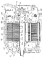
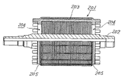
次に、本発明の第3の実施の形態について説明する。
図5は本発明の第3の実施の形態における誘導式の電動機のロータの概略図、図6は本発明の第3の実施の形態における誘導式の電動機のロータの側面図である。
図において、201はロータ、202はモータシャフト、203は前記ロータ201の外周部分において、円周方向における複数箇所に等ピッチで配設された銅製の棒、204は該各棒203の両端を連結する端部部材としてのアルミニウム製の短絡環である。
【0030】
この場合、該短絡環204に渦電流が発生するのを抑制するために、前記短絡環204に渦電流発生抑制部としての環状の段部205が形成される。
したがって、前記短絡環204の外周縁と図示しないコイルの内周縁との間のエアギャップが大きくなるので、短絡環204を鎖交する磁束数をその分少なくすることができる。その結果、前記短絡環204に渦電流が発生するのを抑制することができるので、電動機の効率を高くすることができる。
【0031】
また、段部205が形成される分だけロータ201を軽量化することができる。
次に、本発明の第4の実施の形態について説明する。
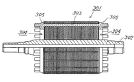
図7は本発明の第4の実施の形態における誘導式の電動機のロータの概略図である。
【0032】
図において、301はロータ、302はモータシャフト、303は銅製の棒、304は端部部材としての短絡環である。
この場合、該短絡環304に渦電流が発生するのを抑制するために、前記短絡環304に渦電流発生抑制部としての環状のテーパ面305が形成される。
したがって、前記短絡環304の外周縁と図示しないコイルの内周縁との間のエアギャップが大きくなるので、短絡環304を鎖交する磁束数をその分少なくすることができる。その結果、前記短絡環304に渦電流が発生するのを抑制することができるので、電動機の効率を高くすることができる。
【0033】
また、テーパ面305が形成される分だけロータ301を軽量化することができる。
次に、本発明の第5の実施の形態について説明する。
図8は本発明の第5の実施の形態における誘導式の電動機のロータの概略図である。
【0034】
図において、401はロータ、402はモータシャフト、403は銅製の棒、404は端部部材としての短絡環である。
この場合、該短絡環404及び棒403に渦電流が発生するのを抑制するために、前記短絡環404及び棒403の両端に渦電流発生抑制部としての環状のテーパ面405が形成される。
【0035】
したがって、前記短絡環404の外周縁と図示しないコイルの内周縁との間のエアギャップが大きくなるので、短絡環404を鎖交する磁束数をその分少なくすることができる。その結果、前記短絡環404に渦電流が発生するのを抑制することができるので、電動機の効率を高くすることができる。
また、テーパ面405が形成される分だけロータ401を軽量化することができる。
【0036】
なお、本発明は前記実施の形態に限定されるものではなく、本発明の趣旨に基づいて種々変形させることが可能であり、それらを本発明の範囲から排除するものではない。
【0037】
【発明の効果】
以上詳細に説明したように、本発明によれば、電動機においては、コアの円周方向における複数箇所に永久磁石が配設されたロータと、該ロータと所定の間隔を置いて配設されたステータと、該ステータに巻装されたコイルとを備える。
そして、前記永久磁石の両端を押さえた状態で固定し、かつ、ロータ及び永久磁石の端面を覆うエンドプレートを有する。
また、該エンドプレートは、前記端面と軸方向において反対側の部分に形成された段部を備え、前記端面を覆わない部分の外周縁とコイルの内周縁との間のエアギャップが大きくされ、前記端面を覆う部分の外周縁が前記端面を覆わない部分の外周縁よりコイルエンドと近接させて配設される。
【0038】
この場合、エンドプレートは、前記ロータ及び永久磁石の端面を覆わない部分の外周縁とコイルの内周縁との間のエアギャップが大きくされるので、エンドプレートを鎖交する磁束数をその分少なくすることができる。その結果、前記エンドプレートに渦電流が発生するのを抑制することができるので、電動機の効率を高くすることができる。
【図面の簡単な説明】
【図1】本発明の第1の実施の形態における同期式の電動機の要部断面図である。
【図2】従来の同期式の電動機の要部断面図である。
【図3】従来の誘導式の電動機のロータの概略図である。
【図4】本発明の第2の実施の形態における同期式の電動機の要部断面図である。
【図5】本発明の第3の実施の形態における誘導式の電動機のロータの概略図である。
【図6】本発明の第3の実施の形態における誘導式の電動機のロータの側面図である。
【図7】本発明の第4の実施の形態における誘導式の電動機のロータの概略図である。
【図8】本発明の第5の実施の形態における誘導式の電動機のロータの概略図である。
【符号の説明】
15 電動機
17 コア
37、201、301、401 ロータ
38 ステータ
55 永久磁石
139 コイル
156、157、256、257 エンドプレート
158、159、205 段部
161、162 コイルエンド
203、303、403 棒
204、304、404 短絡環
258、259、305、405 テーパ面[0001]
BACKGROUND OF THE INVENTION
The present invention relates to an electric motor.
[0002]
[Prior art]
Conventionally, an electric motor has a rotor and a stator disposed around the rotor, and the stator includes a stator core and a stator coil wound around the stator core. When a current is supplied to the stator coil and a rotating magnetic field is formed, the rotor rotates.
[0003]
Further, in a synchronous motor in which magnetic poles are formed by disposing permanent magnets on the rotor, permanent magnets are disposed at a plurality of locations on a core formed by stacking electromagnetic steel plates.
FIG. 2 is a cross-sectional view of a main part of a conventional synchronous motor.
In the figure,
[0004]
A hole is formed in the center of the bottom of the
[0005]
A
The
[0006]
Therefore, the
The
[0007]
A locking projection 27 b is formed on the outer peripheral surface of the
[0008]
The
[0009]
On the other hand, in an induction motor using a squirrel-cage rotor as a rotor, both ends of copper bars disposed at a plurality of locations in the circumferential direction of the rotor are connected by a short-circuit ring.
FIG. 3 is a schematic view of a rotor of a conventional induction motor.
In the figure, 101 is a rotor, 102 is a motor shaft, 103 is a copper rod disposed at a plurality of positions in the circumferential direction at an equal pitch on the outer periphery of the
[0010]
[Problems to be solved by the invention]
However, in the conventional electric motor, in the case of the synchronous motor 15 (FIG. 2), the
[0011]
The
[0012]
In the case of an induction motor, short-
An object of the present invention is to solve the problems of the conventional electric motor and to provide an electric motor that can suppress the generation of eddy current and increase the efficiency.
[0013]
[Means for Solving the Problems]
Therefore, in the electric motor of the present invention, a rotor in which permanent magnets are arranged at a plurality of locations in the circumferential direction of the core, a stator arranged at a predetermined interval from the rotor, and a winding around the stator Coil.
And it has the end plate which fixes in the state which pressed down the both ends of the said permanent magnet, and covers the end surface of a rotor and a permanent magnet.
[0014]
Further, the end plate includes a step portion formed at a portion opposite to the end surface in the axial direction, and an air gap between an outer peripheral edge of the portion not covering the end surface and an inner peripheral edge of the coil is increased, The outer peripheral edge of the part covering the end face is arranged closer to the coil end than the outer peripheral edge of the part not covering the end face.
[0017]
DETAILED DESCRIPTION OF THE INVENTION
Hereinafter, embodiments of the present invention will be described in detail with reference to the drawings.
FIG. 1 is a cross-sectional view of an essential part of a synchronous motor according to a first embodiment of the present invention.
In the figure,
[0018]
A hole is formed in the center of the bottom of the
[0019]
A
The
[0020]
Therefore, the
The
[0021]
A locking projection 27 b is formed on the outer peripheral surface of the
[0022]
The
[0023]
By the way, in order to cover the end surfaces of the
[0024]
Therefore, when an alternating current is supplied to the
Therefore, in order to suppress the generation of eddy currents in the
[0025]
Accordingly, since the air gap between the outer peripheral edge of the
[0026]
Further, the
Next, a second embodiment of the present invention will be described.
FIG. 4 is a cross-sectional view of a main part of the synchronous motor according to the second embodiment of the present invention. In addition, about the thing which has the same structure as 1st Embodiment, the description is abbreviate | omitted by providing the same code | symbol.
[0027]
In this case, in order to suppress the generation of eddy currents in the
Therefore, since the air gap between the outer peripheral edge of the
[0028]
Further, the
In the first and second embodiments, the
[0029]
Next, a third embodiment of the present invention will be described.
FIG. 5 is a schematic view of the rotor of the induction motor according to the third embodiment of the present invention, and FIG. 6 is a side view of the rotor of the induction motor according to the third embodiment of the present invention.
In the figure, 201 is a rotor, 202 is a motor shaft, 203 is a copper bar disposed at a plurality of positions in the circumferential direction at an equal pitch, and 204 is connected to both ends of each
[0030]
In this case, in order to suppress the generation of eddy current in the short-
Therefore, since the air gap between the outer peripheral edge of the short-
[0031]
Further, the
Next, a fourth embodiment of the present invention will be described.
FIG. 7 is a schematic view of the rotor of the induction motor according to the fourth embodiment of the present invention.
[0032]
In the figure, 301 is a rotor, 302 is a motor shaft, 303 is a copper rod, and 304 is a short circuit ring as an end member.
In this case, in order to suppress the generation of eddy currents in the short-
Therefore, since the air gap between the outer peripheral edge of the short-
[0033]
Further, the
Next, a fifth embodiment of the present invention will be described.
FIG. 8 is a schematic diagram of a rotor of an induction motor according to a fifth embodiment of the present invention.
[0034]
In the figure, 401 is a rotor, 402 is a motor shaft, 403 is a copper rod, and 404 is a short-circuit ring as an end member.
In this case, in order to suppress the generation of eddy currents in the short-
[0035]
Therefore, since the air gap between the outer peripheral edge of the short-
Further, the
[0036]
In addition, this invention is not limited to the said embodiment, It can change variously based on the meaning of this invention, and does not exclude them from the scope of the present invention.
[0037]
【The invention's effect】
As described above in detail, according to the present invention, in the electric motor, the rotor in which the permanent magnets are disposed at a plurality of locations in the circumferential direction of the core, and the rotor is disposed at a predetermined interval. A stator and a coil wound around the stator are provided.
And it has the end plate which fixes in the state which pressed down the both ends of the said permanent magnet, and covers the end surface of a rotor and a permanent magnet.
Further, the end plate includes a step portion formed in a portion opposite to the end surface in the axial direction, and an air gap between an outer peripheral edge of the portion not covering the end surface and an inner peripheral edge of the coil is increased, The outer peripheral edge of the part covering the end face is arranged closer to the coil end than the outer peripheral edge of the part not covering the end face.
[0038]
In this case, since the air gap between the outer peripheral edge of the end plate that does not cover the end faces of the rotor and the permanent magnet and the inner peripheral edge of the coil is increased in the end plate, the number of magnetic fluxes linking the end plate is reduced accordingly. can do. As a result, the generation of eddy current in the end plate can be suppressed, and the efficiency of the electric motor can be increased.
[Brief description of the drawings]
FIG. 1 is a cross-sectional view of a main part of a synchronous motor according to a first embodiment of the present invention.
FIG. 2 is a cross-sectional view of a main part of a conventional synchronous motor.
FIG. 3 is a schematic view of a rotor of a conventional induction motor.
FIG. 4 is a cross-sectional view of a main part of a synchronous motor according to a second embodiment of the present invention.
FIG. 5 is a schematic diagram of a rotor of an induction motor according to a third embodiment of the present invention.
FIG. 6 is a side view of a rotor of an induction motor according to a third embodiment of the present invention.
FIG. 7 is a schematic view of a rotor of an induction motor according to a fourth embodiment of the present invention.
FIG. 8 is a schematic diagram of a rotor of an induction motor according to a fifth embodiment of the present invention.
[Explanation of symbols]
15
Claims (1)
Priority Applications (1)
| Application Number | Priority Date | Filing Date | Title |
|---|---|---|---|
| JP26152797A JP3633232B2 (en) | 1997-09-26 | 1997-09-26 | Electric motor |
Applications Claiming Priority (1)
| Application Number | Priority Date | Filing Date | Title |
|---|---|---|---|
| JP26152797A JP3633232B2 (en) | 1997-09-26 | 1997-09-26 | Electric motor |
Publications (2)
| Publication Number | Publication Date |
|---|---|
| JPH1198733A JPH1198733A (en) | 1999-04-09 |
| JP3633232B2 true JP3633232B2 (en) | 2005-03-30 |
Family
ID=17363144
Family Applications (1)
| Application Number | Title | Priority Date | Filing Date |
|---|---|---|---|
| JP26152797A Expired - Lifetime JP3633232B2 (en) | 1997-09-26 | 1997-09-26 | Electric motor |
Country Status (1)
| Country | Link |
|---|---|
| JP (1) | JP3633232B2 (en) |
Families Citing this family (3)
| Publication number | Priority date | Publication date | Assignee | Title |
|---|---|---|---|---|
| JP2006197696A (en) * | 2005-01-12 | 2006-07-27 | Toyota Motor Corp | Rotor structure of rotating electrical machine |
| JP2010213460A (en) * | 2009-03-10 | 2010-09-24 | Toyota Motor Corp | Motor and drive mechanism |
| JP7203175B1 (en) * | 2021-10-18 | 2023-01-12 | 三菱電機株式会社 | Rotating electric machine |
-
1997
- 1997-09-26 JP JP26152797A patent/JP3633232B2/en not_active Expired - Lifetime
Also Published As
| Publication number | Publication date |
|---|---|
| JPH1198733A (en) | 1999-04-09 |
Similar Documents
| Publication | Publication Date | Title |
|---|---|---|
| US7514833B2 (en) | Axial gap permanent-magnet machine with reluctance poles and PM element covers | |
| US6683397B2 (en) | Electric machine having at least one magnetic field detector | |
| JP4311643B2 (en) | Method for manufacturing permanent magnet type rotating electric machine and method for manufacturing permanent magnet type synchronous generator for wind power generation | |
| US6064132A (en) | Armature structure of a radial rib winding type rotating electric machine | |
| US6242834B1 (en) | Brushless polyphase machine, in particular motor vehicle alternator | |
| JPH0720360B2 (en) | Dynamo Electric Machine and Stator Assembly | |
| CN101981785A (en) | Rotating electrical machine | |
| US10749385B2 (en) | Dual magnetic phase material rings for AC electric machines | |
| JP6709712B2 (en) | Synchronous reluctance type rotating electric machine | |
| US20160254715A1 (en) | Single-phase brushless motor | |
| JP2007043897A (en) | Salient pole electrical machine | |
| JP2000278903A (en) | Electric motor and method of manufacturing the same | |
| JP2005506820A (en) | Axial flux permanent magnet generator / motor | |
| JP2005506820A5 (en) | ||
| JP3633232B2 (en) | Electric motor | |
| JP4415176B2 (en) | Induction motor having a ring-shaped stator coil | |
| WO2022237923A1 (en) | Brushless dc electric motor | |
| CN113615041A (en) | Rotating electrical machine | |
| RU2246167C1 (en) | Face-type electrical machine | |
| WO2018221449A1 (en) | Electric motor | |
| JP4482918B2 (en) | Permanent magnet type electric motor having ring-shaped stator coil | |
| JP2003333811A (en) | Induction motor having a plurality of axially divided stator windings | |
| JP4491211B2 (en) | Permanent magnet rotating electric machine | |
| EP3499686A2 (en) | Switched reluctance electric machine including pole flux barriers | |
| US20230073322A1 (en) | Permanent magnet module for a permanent magnet machine |
Legal Events
| Date | Code | Title | Description |
|---|---|---|---|
| A131 | Notification of reasons for refusal |
Free format text: JAPANESE INTERMEDIATE CODE: A131 Effective date: 20040316 |
|
| A521 | Written amendment |
Free format text: JAPANESE INTERMEDIATE CODE: A523 Effective date: 20040513 |
|
| TRDD | Decision of grant or rejection written | ||
| A01 | Written decision to grant a patent or to grant a registration (utility model) |
Free format text: JAPANESE INTERMEDIATE CODE: A01 Effective date: 20041207 |
|
| A61 | First payment of annual fees (during grant procedure) |
Free format text: JAPANESE INTERMEDIATE CODE: A61 Effective date: 20041220 |
|
| R150 | Certificate of patent or registration of utility model |
Free format text: JAPANESE INTERMEDIATE CODE: R150 |
|
| FPAY | Renewal fee payment (event date is renewal date of database) |
Free format text: PAYMENT UNTIL: 20090107 Year of fee payment: 4 |
|
| FPAY | Renewal fee payment (event date is renewal date of database) |
Free format text: PAYMENT UNTIL: 20090107 Year of fee payment: 4 |
|
| FPAY | Renewal fee payment (event date is renewal date of database) |
Free format text: PAYMENT UNTIL: 20100107 Year of fee payment: 5 |
|
| FPAY | Renewal fee payment (event date is renewal date of database) |
Free format text: PAYMENT UNTIL: 20100107 Year of fee payment: 5 |
|
| FPAY | Renewal fee payment (event date is renewal date of database) |
Free format text: PAYMENT UNTIL: 20110107 Year of fee payment: 6 |
|
| FPAY | Renewal fee payment (event date is renewal date of database) |
Free format text: PAYMENT UNTIL: 20120107 Year of fee payment: 7 |
|
| FPAY | Renewal fee payment (event date is renewal date of database) |
Free format text: PAYMENT UNTIL: 20130107 Year of fee payment: 8 |
|
| FPAY | Renewal fee payment (event date is renewal date of database) |
Free format text: PAYMENT UNTIL: 20140107 Year of fee payment: 9 |
|
| EXPY | Cancellation because of completion of term |