JP3634490B2 - Impulse response measurement device in sound field - Google Patents
Impulse response measurement device in sound field Download PDFInfo
- Publication number
- JP3634490B2 JP3634490B2 JP06492696A JP6492696A JP3634490B2 JP 3634490 B2 JP3634490 B2 JP 3634490B2 JP 06492696 A JP06492696 A JP 06492696A JP 6492696 A JP6492696 A JP 6492696A JP 3634490 B2 JP3634490 B2 JP 3634490B2
- Authority
- JP
- Japan
- Prior art keywords
- signal
- impulse response
- band
- response
- impulse
- Prior art date
- Legal status (The legal status is an assumption and is not a legal conclusion. Google has not performed a legal analysis and makes no representation as to the accuracy of the status listed.)
- Expired - Fee Related
Links
Images


Landscapes
- Reverberation, Karaoke And Other Acoustics (AREA)
- Measurement Of Mechanical Vibrations Or Ultrasonic Waves (AREA)
Description
【0001】
【発明の属する技術分野】
本発明は、音場におけるインパルス応答を測定する装置に係わり、特に高精度にインパルス応答を自動測定することのできる装置に関する。
【0002】
[発明の概要]
本発明は、室内の音響伝達特性を表すインパルス応答をクロススペクトル法によって求める場合、測定されるインパルス応答のノイズ成分を考慮することにより高精度なインパルス応答を自動的に求める装置に関するものである。
【0003】
従来のインパルス応答を求める自動測定法は広い測定周波数帯域に渡って必要十分な信号対雑音比(以下S/N比と称する)が取れているかの判断が難しく自動測定が困難であった。
【0004】
本発明では、算出されるインパルス応答を平均化していく段階で前後のインパルス応答波形についての差のノルムを基に応答信号のノイズ成分を、監視する評価値として採用することにより高精度なインパルス応答を自動的に求めることを可能にする装置である。
【0005】
また、他の発明では、測定音源として使用される楽音信号と、得られる応答信号とをいくつかの周波数帯域に分割し、帯域毎にコヒーレンス関数の値を基に十分なS/N比を持った応答かどうかを判断し、不十分なS/N比を持つ応答については平均化の操作を行わないことによって有効な平均化操作を行い、高精度なインパルス応答を自動的に短時間で求めることを可能にする装置である。
【0006】
【従来の技術】
従来より、室内の音響伝達特性を測定する場合には、クロススペクトル法を用いたものが知られている(参考文献1:城戸健一著『デジタル信号処理入門』、P47−P49、丸善(1985))。
【0007】
クロススペクトル法によってインパルス応答を求める場合、測定結果として得られる応答のうち真のインパルス応答を信号Sとし、その他の成分を雑音Nとしたとき、S/N比は次の式1のように表される。
【0008】
【数1】

従来のインパルス応答測定において、広帯域に渡って十分なS/N比を持つインパルス応答を得るには、予め必要と思われる時間以上の長時間の測定を行い、得られた応答波形に平均化処理を行った上で、インパルス応答のS/N比を目で確認する必要があった。
【0010】
しかし、実際の音響測定では、真のインパルス応答が不明であるために、S/N比の算出が不可能であり、このS/N比を用いた測定の自動化も困難であった。
【0011】
ところで、インパルス応答を求めるための測定用の信号源に広帯域の測定用信号を用いた場合は、精度良く室内の音響伝達特性が測定できる反面、ホールやスタジオ等の室内の音響伝達特性を知るには聴衆が入るなど、実際の運用状態における特性を知ることが最も重要となる。
【0012】
運用状態の特性を知るために室内に聴衆がいる状態の特性が必要な場合、従来のインパルス応答の測定においは、特殊な測定信号を使用している。このため、聴衆が聞き苦しかったり、聴覚に悪い影響を与えてしまう等の心配があり、運用状態での測定は困難であった。
【0013】
そこで、測定用の信号源として聴衆の聞き慣れた楽音を用いる方法が採用されている(参考文献2:西隆司、古川宣一 ”楽音信号を用いた室のインパルス応答推定について” 日本音響学会講演論文集(1998/10) )。
【0014】
しかし、楽音を測定音源として使用した場合に得られる応答信号の周波数成分は定常的に広帯域なものではなく、時々刻々に変化している。このため、S/N比が広帯域に渡って十分な応答を得るためには、やはり予め必要と思われる時間以上の長時間の測定を行わねばならない。また、得られた応答波形に多くの平均化処理を行った上で、インパルス応答のS/N比を目視により確認しなければならなかった。
【0015】
【発明が解決しようとする課題】
このように、上述した従来のインパルス応答測定においては、真のインパルス応答が不明であることから、S/N比の算出が不可能であるという問題がある。一方、測定信号源として楽音を用いる従来例では、楽音信号の性質上、得られる応答信号の周波数特性は定常的でなく時々刻々に変化するため、広い測定周波数帯域に渡って必要十分なS/N比が取れているかの判断が難しく精度の高いインパルス応答を得るのは困難であるという問題があった。
【0016】
本発明は上記の事情に鑑みてなされたものであり、その目的は、必要以上に時間をかけることなく、かつ聴衆に苦痛を与えること無く自動的に十分なS/N比を持つインパルス応答を得ることを可能にし、高精度な音響伝達特性を得ることのできる音場におけるインパルス応答測定装置を提供することにある。
【0017】
【課題を解決するための手段】
上記の目的を達成するために請求項1に記載の発明は、音源信号と、当該音源信号を音場に放射・収音して得た応答信号を入力するとともに、第1〜第4処理を行うインパルス応答測定装置であって、第1処理は、同一時刻における音源信号と応答信号を一定長の時間窓で切り出し、第2処理は、第1処理で切り出した音源信号と応答信号からクロススペクトル法を用いてインパルス応答を算出し、第3処理は、第2処理で算出したインパルス応答とそれまでに算出したインパルス応答の平均である第1平均インパルス応答と、それまでに算出したインパルス応答の平均である第2平均インパルス応答の差のノルムに基づく評価値を算出し、第4処理は、第3処理で求めた評価値がしきい値を下回った場合は、第1平均インパルス応答を真のインパルス応答として出力し、そうでない場合は、時刻をシフトした時間窓にて第1処理に戻ることを特徴としている。
【0018】
請求項1の発明では、逐次平均化処理を行う中で、平均化操作を行う前後のインパルス応答の差のノルムを基にした評価値を導入している。一般的に平均化が行われるに従いインパルス応答のノイズ成分が減少し、それと共に評価値は0%に漸近していく。評価値が十分小さくなった時点で測定を終了するという判断を行う。これにより、必要以上に時間をかけることなく、自動的に十分なS/N比を持つインパルス応答を得ることが可能となる。
【0019】
請求項2の発明は、楽音信号と、当該楽音信号を音場に放射・収音して得た応答信号を入力するとともに、第1〜第5処理を行うインパルス応答測定装置であって、第1処理は、同一時刻における楽音信号と応答信号を一定長の時間窓で切り出して、複数の帯域に分割し、第2処理は、各帯域の楽音信号と応答信号に基づいて、帯域毎にコヒーレンス関数値を算出し、コヒーレンス関数値がしきい値を上回る帯域を有効とし、第3処理は、第2処理で有効とした帯域の楽音信号と応答信号からクロススペクトル法を用いて帯域別インパルス応答を算出し、第4処理は、第3処理で算出した帯域別インパルス応答を帯域毎に平均化して帯域別平均インパルス応答を算出し、第5処理は、全ての帯域において平均化した回数が設定された回数に達した場合は、各帯域別平均インパルス応答を合成して全帯域インパルス応答を生成し、そうでない場合には、時刻をシフトした時間窓にて第1処理に戻ることを特徴としている。
【0020】
請求項2の発明では、音源となる楽音信号とその応答信号とから、ある窓長で波形を切り出した後、周波数軸上で狭帯域に分割し、帯域毎に音源信号と応答信号とのコヒーレンス関数値を求め、このコヒーレンス関数値に基づいてS/N比の評価を行う。楽音信号は時間経過と共に周波数特性が変動しているために、切り出した時刻と帯域によってS/N比が変動する。
【0021】
S/N比とコヒーレンス関数とは1対1の対応関係にあるため、S/N比の変動に伴ってコヒーレンス関数も増減する。コヒーレンス関数の値が予め設定したしきい値よりも大きい場合には、S/N比が十分とれていると考えられるので、クロススペクトル法の処理を続行して平均化処理を行う。一方、コヒーレンス関数の値が前記しきい値よりも小さい場合には、S/N比が十分でないと考えられるので、その後の処理は行わないという判断をする。従って、S/N比が小さい帯域の伝達特性は平均化操作に採用しないので、収束判定が容易になり、少ない平均回数で処理を終了することができ、測定時間の短縮化、測定精度の向上が可能となる。
【0022】
請求項3の発明は、請求項2に記載のインパルス応答測定装置において、第2処理は、ある帯域のコヒーレンス関数値が、設定期間しきい値を下回る場合には、楽音信号を切り替える旨を促す警告信号を生成することを特徴としている。
【0023】
請求項3の発明では、楽音信号が全ての周波数成分を含んでおらず、ある帯域についてコヒーレンス関数値が長時間に渡ってしきい値を越えない場合には、警告を発して楽音切り替えを促すようにしているので、信号処理上は無駄の楽音を長時間に渡って放射し続けることが防止され、測定時間の短縮化、測定精度の向上が可能となる。
【0024】
【発明の実施の形態】
<第1の実施の形態>
《第1の実施の形態の構成》
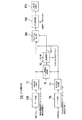
図1は本発明の第1の実施の形態を示すブロック図である。
【0025】
同図に示すように、このインパルス応答測定装置は、信号源1Aの音源信号Sa をアンプ2により増幅して室内3に放射する一方、この放射された音源信号Sa を収音し応答信号Sb としてA/D変換器4によりディジタル信号に変換した後、信号処理部5Aに供給するように構成されている。
【0026】
この場合、信号源1Aはテープ等で構成され、この信号源1Aの音源信号Sa はアンプ2を介して室内3に設けられたスピーカ6から出力され、同じく室内3に設けられたマイクロホン7によって収音される。室内3は、ホールやスタジオ、あるいは一般家庭等、測定対象となる種々の環境が考えられる。
【0027】
この実施の形態における信号処理部5Aは、図2に示すように、2つのゲート回路6A,7Aと、クロススペクトル法処理部8Aと、平均化処理部9Aと、計算結果格納部10Aと、評価値演算部11と、比較演算部12とを備えている。
【0028】
ゲート回路6Aには信号源1Aから出力された音源信号Sa が供給され、また、ゲート回路7Aにはマイクロホン7で収音された応答信号Sb が供給されている。各ゲート回路6A,7Aにおける信号の取り込み開始時刻tstは、t1 ,t2 ,t3 ,…,tn に設定されており、その取り込み時間はTに設定されている。すなわち、このゲート回路6A,7Aでは、応答波形は設定された時間長単位で切り出される。
【0029】
クロススペクトル法処理部8Aは、ゲート回路6A,7Aから取り込まれた信号に対してクロススペクトル法によりインパルス応答を算出する。
【0030】
平均化処理部9Aは、クロススペクトル法処理部8Aで算出されたインパルス応答を平均化して計算結果格納部10Aに供給する。
【0031】
計算結果格納部10Aは、平均化処理部9Aで算出されたインパルス応答の平均化値を格納するとともに、後述する比較演算部12から設定終了トリガ信号が出力された時、格納されているインパルス応答の平均化値を真のインパルス応答として出力する。
【0032】
評価値演算部11は、平均化処理部9Aによってインパルス応答の平均化演算がされる度に、インパルス応答の差のノルムの評価値(DR値)を後述する第2式に基づいて算出する。
【0033】
比較演算部12は、評価値演算部11で算出されたDR値を予め設定されたしきい値と比較し、DR値がしきい値より小さい場合には、設定終了トリガ信号を出力する。この場合、しきい値としては、“0”に近い値が設定される。
【0034】
《第1の実施の形態の作用》
次に本実施の形態の作用を図3のフローチャートを参照して説明する。
【0035】
信号源1Aの音源信号Sa はアンプ2で増幅された後、スピーカ6に供給されると共に、A/D変換器4に供給されてディジタル化される。スピーカ6から室内に放射された音源信号Sa はマイクロホン7で収音され応答信号Sb となりA/D変換器4に供給されてディジタル化される。
【0036】
前記ディジタル化された音源信号Sa は信号処理部5Aのゲート回路6Aに供給され、また、前記ディジタル化された応答信号Sb は信号処理部5Aのゲート回路7Aに供給される。
【0037】
ゲート回路6A、及び7Aでは入力された音源信号Sa 、及び応答信号Sb に対して時刻t1 ,t2 ,t3 ,…,tn における一定区間(取り込み時間T)の波形が切り出される。クロススペクトル法処理部8Aでは最初の時刻t1 における(すなわち、1つめの)インパルス応答が算出される(ステップST1)。次いで、切り出された部分が時間Tだけシフトされ、時刻t2 におけるインパルス応答が算出される(ステップST2)。
【0038】
平均化処理部では、時刻t1 と時刻t2 で得られたインパルス応答の平均が演算される。計算結果は計算結果格納部10Aに格納される(ステップST3)。
【0039】
次いで、評価値演算部11では、平均化を実行する都度、次の式2に示すようなインパルス応答の差のノルムの評価値(DR値)が算出される(ステップST4)。
【0040】
【数2】
Ek (n) :平均化をk回行ったときのインパルス応答波形をN個の サンプルに分割したときのnサンプル目の値
【0041】
比較演算部12では、算出されたDR値が設定値(しきい値)と比較して小さいか否かが判定される(ステップST5)。平均化処理部9Aで実行される平均化が十分行われていない段階では、得られるインパルス応答にはノイズ成分が大量に含まれており、得られる平均化前後のDR値は大きな値となる。この場合、処理はステップST2に戻り、次の時刻t3 におけるインパルス応答が算出され、次いで、t1 ,t2 ,t3 で求められたインパルス応答の平均が算出される。そして、平均化前後のDR値が再び算出され、このDR値が設定値より小さいか否かが判定される(ステップST2〜ST5)。
【0042】
このように、時刻t1 ,t2 ,t3 ,…,tn におけるインパルス応答が逐次算出され(ステップST2)、得られたインパルス応答が逐次平均化され(ステップST3)、そのDR値が算出される(ステップST4)。
【0043】
インパルス応答の平均化が十分行われると差のノルムは0へ漸近する。これに伴って、DR値も0(%)に漸近していく。そして、DR値が設定値を下回ったときに比較演算部12は測定終了トリガ信号を出力する。計算結果格納部10Aは、この測定終了トリガ信号を入力すると、このとき格納されている最新のインパルス応答平均値を真のインパルス応答として出力する。
【0044】
《第1の実施の形態の効果》
このように、この実施の形態によれば、クロススペクトル法によって測定される室内の音響伝達特性を表すインパルス応答のS/N比を大きくするために、必要以上に平均化回数を増やすことなく、ノイズ成分をDR値を基にして定量的に評価できる。従って、平均化回数を減らすことができるため、測定時間の短縮が可能となるばかりでなく、時間経過に伴って変化してしまう伝達特性に対して追随性の良い測定が可能となる。
【0045】
<第2の実施の形態>
《第2の実施の形態の構成》
図4は本発明の第2の実施の形態を示すブロック図である。
【0046】
同図に示すように、このインパルス応答測定装置は、信号源1Bの音源信号Sc をアンプ2により増幅して室内3に放射する一方、この放射された音源信号Sc を収音し応答信号Sb としてA/D変換器4によりディジタル信号に変換した後、信号処理部5Bに供給するように構成されている。
【0047】
この場合、信号源1Bは楽音を収録したテープ等で構成される。また、この音源として使用する楽音は高い周波数成分まで含んでいる楽音が望ましい。例えば、大編成のオーケストラ、電気楽器による音楽、打楽器中心の音楽など、複数の楽音テープが用意されている。この信号源1Bの音源信号Sc はアンプ2を介して室内3に設けられたスピーカ6から出力され、同じく室内3に設けられたマイクロホン7によって収音される。室内3は、ホールやスタジオ、あるい一般家庭等、測定対象となる種々の環境が考えられる。
【0048】
この実施の形態における信号処理部5Bは、図5に示すように、その機能上、2つのゲート回路6B,7Bと、各ゲート回路6B,7B別に設けられた帯域分割フィルタ部13,14と、コヒーレンス関数値演算部15と、比較演算部16と、クロススペクトル法処理部8Bと、平均化処理部9Bと、計算結果格納部10Bとを備えている。
【0049】
ゲート回路6Bには、信号源1Bから出力された音源信号Sc が供給され、また、ゲート回路7Bにはマイクロホン7で収音された応答信号Sd が供給されている。各ゲート回路6B,7Bにおける信号の取り込み開始時刻tstは、t1 ,t2 ,t3 ,…,tn であり、取り込み時間はTに設定されている。
【0050】
帯域分割フィルタ部13は、供給された音源信号Sc を1/1 オクターブ帯域に分割するフィルタを備えており、分割された各帯域毎の音源信号Sc をコヒーレンス関数値演算部15に供給する。
【0051】
帯域分割フィルタ部14は、供給された応答信号Sd を1/1 オクターブ帯域に分割するフィルタを備えており、分割された各帯域毎の応答信号Sd をコヒーレンス関数値演算部15に供給する。
【0052】
コヒーレンス関数値演算部15は、各帯域毎の音源信号Sc と応答信号Sd とを入力し帯域毎のコヒーレンス関数値を算出する。
【0053】
比較演算部16は、コヒーレンス関数値演算部15により求められたコヒーレンス関数値が予め設定されたしきい値を下回った場合に、クロススペクトル処理を行わないという制御信号と、音源切り替え警告信号を生成する。制御信号はクロススペクトル法処理部8Bに供給されている。
【0054】
クロススペクトル法処理部8Bは、帯域分割フィルタ部13,14を介して帯域分割された各信号成分に対してクロススペクトル法によりインパルス応答を算出する処理を、比較演算部16から前記制御信号が供給されるまで実行する。
【0055】
平均化処理部9Bは、前述した時刻t1 、t2 ,…,tn をシフトしながら、逐次インパルス応答を平均化する演算を実行する。
【0056】
計算結果格納部10Bは、平均化処理部9Bで演算されたインパルス応答の平均化値を格納するとともに、後述する比較演算部12から設定終了トリガ信号が出力された時、格納されている各帯域インパルス応答の平均化値を合成し、広帯域のインパルス応答を算出する。
【0057】
《第2の実施の形態の作用》
次に本実施の形態の作用を図6のフローチャートを参照して説明する。なお、図6のフローチャートにおいては、原則として各算出処理や各判定処理は帯域別に並行して実行されているものとする。
【0058】
第1の実施の形態で説明したと同様、信号源1Bの音源信号(楽音信号)SC はアンプ2で増幅された後、スピーカ6に供給されると共に、A/D変換器4に供給されてディジタル化される。スピーカ6から室内に放射された音源信号Sc はマイクロホン7で収音され応答信号Sd となりA/D変換器4に供給されてディジタル化される。
【0059】
前記ディジタル化された音源信号Sc は信号処理部5Bのゲート回路6Bに供給され、また、前記ディジタル化された応答信号Sd は信号処理部5Bのゲート回路7Bに供給される。
【0060】
ゲート回路6B、及び7Bでは入力された音源信号Sc 、及び応答信号Sd に対して時刻t1 ,t2 ,t3 ,…,tn における一定時間窓(取り込み時間T)の波形が切り出される。次いで、帯域分割フィルタ部13、及び14では、それぞれ切り出された波形が1/1 オクターブ帯域に分割され、それぞれコヒーレンス関数値演算部15に供給される(ステップST11)。
【0061】
コヒーレンス関数演算部15では、帯域毎のコヒーレンス関数値が次の式3に基づいて算出される(ステップST12)。
【0062】
【数3】
比較演算部16では、算出されたコヒーレンス関数値が予め設定されたしきい値と比較され、コヒーレンス関数値がしきい値よりも小さい場合には、その後の処理をスキップさせる制御信号をクロススペクトル法処理部8Bに供給するとともに、時間窓をシフトさせ、次の時刻t2 における切り出された波形に対する前記一連の処理を実行する(ステップST15)。また、コヒーレンス関数値が設定値よりも小さい場合において、音源として用いられている楽音信号が全ての周波数成分を含んでおらず、ある帯域についてコヒーレンス関数値が長時間に渡ってしきい値を越えない場合には(ステップST14Yes )、楽音信号を別の楽音信号に切り替える警告信号を出力する。これにより、信号源1Bの音源信号は別の楽音信号に切り替わった後、ステップST11からの処理を開始する(ステップST16)。
【0064】
コヒーレンス関数値がしきい値を越えた帯域のデータは有効なものとし、クロススペクトル法処理部では、クロススペクトル法によってインパルス応答が算出される(ステップST17)。
【0065】
そして、平均化処理部9Bでは、時間窓をシフト(開始時間t3 ,…,tn 、切り出し時間T)させつつ逐次求められたインパルス応答が平均化されて計算結果格納部10Bに格納される(ステップST18)。
【0066】
平均化処理部9Bでは、平均回数が設定された回数よりも大きいか否かが判定され、設定された平均回数を終了すると(ステップST19YES )、測定終了トリガ信号が出力されて、平均化処理が終了する。計算結果格納部10Bは、測定終了トリガ信号が入力されると、各帯域のインパルス応答を合成し、全帯域のインパルス応答を算出して測定を終了する(ステップST20)。
【0067】
《第2の実施の形態の効果》
このようにこの実施の形態によれば、実際に室内で使用される状態での音響伝達特性を測定できることにより、聴衆がいる等の現実により近い状態の室内の音響伝達特性を精度良く知ることができる。ここで得られる知見を発展させるとこにより、人が居ない状態から人が居る状態を精度良く予測することが可能となり、設計段階で完成後の運用状態の音響伝達特性を予測することができ、音響設計の精度も向上する。
【0068】
また、ホール等の特殊な施設でなく一般家庭のおいても音響機器等のこの実施の形態を適用して、楽音による測定を行うことにより、室のユーザー(聴取者)が意識することなく測定をすることができる。これにより、室内、音響機器伝達特性を知ることができれば、その特性を等化することも可能となり、仮に聴取環境が異なっても音質、定位を初めとする音声制作上の細かい効果を同一条件とすることができる。
【0069】
<変形例>
なお、上述した第2の実施の形態では、帯域分割フィルタ部13,14により、供給された音源信号Sc 、応答信号Sd を狭帯域の信号に分割するようにしたが、コヒーレンス関数値演算部15において帯域別の関数値を算出するようにしても良い。このように構成することにより、帯域分割フィルタ部13,14を省略でき、装置構成が簡素化される。
【0070】
【発明の効果】
以上説明したように請求項1の発明によれば、必要以上に時間をかけることなく、自動的に十分なS/N比を持つインパルス応答を得ることが可能となる。
【0071】
請求項2の発明によれば、S/N比が小さい帯域の伝達特性は平均化操作に採用しないので、収束判定が容易になり、少ない平均回数で処理を終了することができ、測定時間の短縮化、測定精度の向上が可能となる。
【0072】
請求項3の発明によれば、楽音信号が全ての周波数成分を含んでおらず、ある帯域についてコヒーレンス関数値が長時間に渡ってしきい値を越えない場合には、警告を発して楽音切り替えを促すようにしているので、信号処理上は無駄の楽音を長時間に渡って放射し続けることが防止され、測定時間の短縮化、測定精度の向上が可能となる。
【図面の簡単な説明】
【図1】本発明の第1の実施の形態を示す構成図である。
【図2】図1に示す第1の実施の形態における信号処理部の構成を示すブロック図である。
【図3】第1の実施の形態における処理手順を説明するフローチャートである。
【図4】本発明の第2の実施の形態を示す構成図である。
【図5】図4に示す第2の実施の形態における信号処理部の構成を示すブロック図である。
【図6】第2の実施の形態における処理手順を説明するフローチャートである。
【符号の説明】
1A,1B 信号源
2 アンプ
3 室内
4 A/D変換器
5A,5B 信号処理部
6A,6B,7A,7B ゲート回路
8A,8B クロススペクトル法処理部
9A,9B 平均化処理部
10A,10B 計算結果格納部
11 評価値演算部
12,16 比較演算部
13,14 帯域分割フィルタ部
15 コヒーレンス関数値演算部[0001]
BACKGROUND OF THE INVENTION
The present invention relates to an apparatus for measuring an impulse response in a sound field, and more particularly to an apparatus capable of automatically measuring an impulse response with high accuracy.
[0002]
[Summary of Invention]
The present invention relates to an apparatus for automatically obtaining a highly accurate impulse response by considering a noise component of a measured impulse response when an impulse response representing an indoor acoustic transfer characteristic is obtained by a cross spectrum method.
[0003]
In the conventional automatic measurement method for obtaining the impulse response, it is difficult to determine whether a necessary and sufficient signal-to-noise ratio (hereinafter referred to as S / N ratio) is obtained over a wide measurement frequency band, and automatic measurement is difficult.
[0004]
In the present invention, the noise component of the response signal is adopted as an evaluation value to be monitored based on the norm of the difference between the preceding and succeeding impulse response waveforms at the stage of averaging the calculated impulse responses, thereby providing a highly accurate impulse response. It is a device that makes it possible to automatically obtain.
[0005]
In another invention, the musical sound signal used as a measurement sound source and the obtained response signal are divided into several frequency bands, and each band has a sufficient S / N ratio based on the value of the coherence function. If the response has an insufficient S / N ratio, an effective averaging operation is performed by not performing the averaging operation, and a highly accurate impulse response is automatically obtained in a short time. It is a device that makes it possible.
[0006]
[Prior art]
Conventionally, in order to measure the acoustic transfer characteristics in a room, one using a cross spectrum method is known (Reference 1: Kenichi Kido, “Introduction to Digital Signal Processing”, P47-P49, Maruzen (1985). ).
[0007]
When the impulse response is obtained by the cross spectrum method, the S / N ratio is expressed by the following equation 1 when the true impulse response of the response obtained as a measurement result is the signal S and the other component is the noise N. Is done.
[0008]
[Expression 1]
In the conventional impulse response measurement, in order to obtain an impulse response with a sufficient S / N ratio over a wide band, measurement is performed for a long time that is longer than necessary, and the obtained response waveform is averaged. It was necessary to visually confirm the S / N ratio of the impulse response.
[0010]
However, in actual acoustic measurement, since the true impulse response is unknown, it is impossible to calculate the S / N ratio, and it is difficult to automate the measurement using this S / N ratio.
[0011]
By the way, when a wide-band measurement signal is used as a measurement signal source for obtaining an impulse response, it is possible to accurately measure the acoustic transfer characteristics in a room, but to know the acoustic transfer characteristics in a room such as a hall or a studio. It is most important to know the characteristics in the actual operational state, such as the audience entering.
[0012]
When the characteristic of the state where the audience is in the room is necessary to know the characteristic of the operation state, a special measurement signal is used in the measurement of the conventional impulse response. For this reason, there were concerns that the audience was hard to hear or had a bad influence on hearing, and it was difficult to measure in an operational state.
[0013]
Therefore, the method of using the musical sound familiar to the audience is adopted as the signal source for the measurement (Reference 2: Takashi Nishi, Nobuichi Furukawa "About Impulse Response Estimation in the Room Using Musical Signal" Lecture by the Acoustical Society of Japan Papers (1998/10)).
[0014]
However, the frequency component of the response signal obtained when the musical sound is used as a measurement sound source is not constantly a wide band, but changes every moment. For this reason, in order to obtain a sufficient response over an S / N ratio in a wide band, it is necessary to perform measurement for a long time that is longer than necessary. In addition, it was necessary to visually check the S / N ratio of the impulse response after performing many averaging processes on the obtained response waveform.
[0015]
[Problems to be solved by the invention]
Thus, in the conventional impulse response measurement described above, there is a problem that the S / N ratio cannot be calculated because the true impulse response is unknown. On the other hand, in the conventional example using the musical sound as the measurement signal source, the frequency characteristic of the response signal obtained is not steady due to the nature of the musical sound signal, and changes every moment, so that the necessary S / S is sufficient over a wide measurement frequency band. There is a problem that it is difficult to determine whether the N ratio is obtained, and it is difficult to obtain a highly accurate impulse response.
[0016]
The present invention has been made in view of the above circumstances, and its purpose is to automatically generate an impulse response having a sufficient S / N ratio without taking more time than necessary and without causing pain to the audience. It is an object of the present invention to provide an impulse response measuring apparatus in a sound field that can be obtained and can obtain a highly accurate acoustic transmission characteristic.
[0017]
[Means for Solving the Problems]
In order to achieve the above object, the invention described in claim 1 inputs a sound source signal and a response signal obtained by radiating and collecting the sound source signal in a sound field, and performs the first to fourth processes. An impulse response measuring device to perform, wherein the first process cuts out a sound source signal and a response signal at the same time in a fixed time window, and the second process cross-spectrums from the sound source signal and the response signal cut out in the first process. An impulse response is calculated using the method, and the third process includes a first average impulse response that is an average of the impulse response calculated in the second process and the impulse response calculated so far, and the impulse response calculated so far. An evaluation value based on the norm of the difference between the second average impulse responses, which is an average, is calculated. In the fourth process, if the evaluation value obtained in the third process falls below the threshold value, the first average impulse response is true. of Output as impulse response, otherwise, is characterized in that the time at shifted time window to return to the first processing.
[0018]
In the first aspect of the present invention, an evaluation value based on the norm of the difference between impulse responses before and after performing the averaging operation is introduced during the sequential averaging process. In general, the noise component of the impulse response decreases as the averaging is performed, and the evaluation value gradually approaches 0%. It is determined that the measurement is terminated when the evaluation value becomes sufficiently small. This makes it possible to automatically obtain an impulse response having a sufficient S / N ratio without taking more time than necessary.
[0019]
The invention of
[0020]
According to the second aspect of the present invention, after a waveform is cut out with a certain window length from a musical sound signal as a sound source and its response signal, it is divided into narrow bands on the frequency axis, and the coherence between the sound source signal and the response signal for each band A function value is obtained, and the S / N ratio is evaluated based on the coherence function value. Since the frequency characteristic of the musical sound signal varies with time, the S / N ratio varies depending on the cut time and band.
[0021]
Since the S / N ratio and the coherence function have a one-to-one correspondence, the coherence function also increases or decreases as the S / N ratio varies. When the value of the coherence function is larger than a preset threshold value, it is considered that the S / N ratio is sufficient, so the cross spectrum method process is continued and the averaging process is performed. On the other hand, when the value of the coherence function is smaller than the threshold value, it is considered that the S / N ratio is not sufficient, so that the subsequent processing is not performed. Therefore, transfer characteristics in a band with a small S / N ratio are not adopted in the averaging operation, so that it is easy to determine convergence, processing can be completed with a small number of averages, shortening measurement time, and improving measurement accuracy. Is possible.
[0022]
According to a third aspect of the present invention, in the impulse response measuring apparatus according to the second aspect , the second process prompts the user to switch the musical tone signal when the coherence function value of a certain band falls below a set period threshold value. It is characterized by generating a warning signal .
[0023]
According to the third aspect of the present invention, when the tone signal does not include all frequency components and the coherence function value does not exceed the threshold value for a long time in a certain band, a warning is issued to prompt tone switching. As a result, it is possible to prevent unnecessary musical sounds from being radiated for a long time in signal processing, and it is possible to shorten the measurement time and improve the measurement accuracy.
[0024]
DETAILED DESCRIPTION OF THE INVENTION
<First Embodiment>
<< Configuration of the First Embodiment >>
FIG. 1 is a block diagram showing a first embodiment of the present invention.
[0025]
As shown in the figure, this impulse response measuring apparatus amplifies the sound source signal Sa of the signal source 1A by the
[0026]
In this case, the signal source 1A is composed of a tape or the like, and the sound source signal Sa of the signal source 1A is output from the speaker 6 provided in the room 3 via the
[0027]
As shown in FIG. 2, the
[0028]
The sound source signal Sa 1 output from the signal source 1A is supplied to the
[0029]
The cross spectrum
[0030]
The averaging
[0031]
The calculation
[0032]
The evaluation
[0033]
The
[0034]
<< Operation of First Embodiment >>
Next, the operation of the present embodiment will be described with reference to the flowchart of FIG.
[0035]
The sound source signal Sa of the signal source 1A is amplified by the
[0036]
The digitized sound source signal Sa is supplied to the
[0037]
In the
[0038]
In the averaging processing unit, an average of impulse responses obtained at time t1 and time t2 is calculated. The calculation result is stored in the calculation
[0039]
Next, every time averaging is performed, the evaluation
[0040]
[Expression 2]
The
[0042]
In this way, impulse responses at times t1, t2, t3,..., Tn are sequentially calculated (step ST2), the obtained impulse responses are sequentially averaged (step ST3), and the DR value is calculated (step ST2). ST4).
[0043]
When the impulse response is sufficiently averaged, the norm of the difference approaches 0. Along with this, the DR value gradually approaches 0 (%). When the DR value falls below the set value, the
[0044]
<< Effects of First Embodiment >>
Thus, according to this embodiment, in order to increase the S / N ratio of the impulse response representing the acoustic transfer characteristics in the room measured by the cross spectrum method, without increasing the number of averaging more than necessary, The noise component can be quantitatively evaluated based on the DR value. Therefore, since the number of times of averaging can be reduced, not only the measurement time can be shortened, but also a measurement with good followability can be performed with respect to the transfer characteristics that change with the passage of time.
[0045]
<Second Embodiment>
<< Configuration of Second Embodiment >>
FIG. 4 is a block diagram showing a second embodiment of the present invention.
[0046]
As shown in the figure, this impulse response measuring apparatus amplifies the sound source signal Sc of the signal source 1B by the
[0047]
In this case, the signal source 1B is composed of a tape or the like on which music is recorded. In addition, it is desirable that the musical sound used as the sound source includes a high frequency component. For example, a plurality of musical sound tapes are prepared, such as large orchestras, music using electric instruments, and music mainly percussion instruments. The sound source signal Sc of the signal source 1B is output from the speaker 6 provided in the room 3 via the
[0048]
As shown in FIG. 5, the
[0049]
The
[0050]
The band
[0051]
The band
[0052]
The coherence function
[0053]
When the coherence function value obtained by the coherence function
[0054]
The cross spectrum method processing unit 8B supplies the control signal from the comparison operation unit 16 to calculate the impulse response by the cross spectrum method for each signal component band-divided through the band
[0055]
The averaging
[0056]
The calculation
[0057]
<< Operation of Second Embodiment >>
Next, the operation of the present embodiment will be described with reference to the flowchart of FIG. In the flowchart of FIG. 6, in principle, each calculation process and each determination process are executed in parallel for each band.
[0058]
As described in the first embodiment, the sound source signal (musical signal) SC of the signal source 1B is amplified by the
[0059]
The digitized sound source signal Sc is supplied to the
[0060]
In the
[0061]
The coherence
[0062]
[Equation 3]
In the comparison operation unit 16, the calculated coherence function value is compared with a preset threshold value. When the coherence function value is smaller than the threshold value, a control signal for skipping the subsequent processing is applied to the cross spectrum method. While supplying to the process part 8B, a time window is shifted and the said series of processes with respect to the cut-out waveform in the following time t2 are performed (step ST15). In addition, when the coherence function value is smaller than the set value, the tone signal used as a sound source does not contain all frequency components, and the coherence function value exceeds a threshold for a long time for a certain band. If not (step ST14 Yes), a warning signal for switching the tone signal to another tone signal is output. Thereby, after the sound source signal of the signal source 1B is switched to another musical sound signal, the processing from step ST11 is started (step ST16).
[0064]
Data in a band where the coherence function value exceeds the threshold value is valid, and the cross spectrum method processing unit calculates an impulse response by the cross spectrum method (step ST17).
[0065]
Then, the averaging
[0066]
In the averaging
[0067]
<< Effects of Second Embodiment >>
As described above, according to this embodiment, it is possible to accurately measure the acoustic transfer characteristics in a room that is closer to reality, such as the presence of an audience, by measuring the acoustic transfer characteristics in a state where they are actually used indoors. it can. By developing the knowledge obtained here, it becomes possible to accurately predict the state where there is a person from the state where there is no person, and it is possible to predict the acoustic transfer characteristics of the operational state after completion at the design stage, The accuracy of acoustic design is also improved.
[0068]
In addition, it is possible to measure without sound by the user (listener) of the room by applying this embodiment of the audio equipment, etc., in a general household as well as in a special facility such as a hall, etc. Can do. As a result, if it is possible to know the transfer characteristics of indoor and acoustic equipment, it is also possible to equalize the characteristics, and even if the listening environment is different, fine effects on sound production including sound quality and localization are the same conditions. can do.
[0069]
<Modification>
In the second embodiment described above, the supplied sound source signal Sc and response signal Sd are divided into narrowband signals by the band
[0070]
【The invention's effect】
As described above, according to the first aspect of the present invention, it is possible to automatically obtain an impulse response having a sufficient S / N ratio without taking more time than necessary.
[0071]
According to the second aspect of the present invention, since the transfer characteristic of the band having a small S / N ratio is not adopted in the averaging operation, the convergence determination is facilitated, and the processing can be completed with a small average number of times. Shortening and improvement of measurement accuracy are possible.
[0072]
According to the invention of claim 3, when the musical sound signal does not include all frequency components and the coherence function value does not exceed the threshold value for a long time in a certain band, a warning is issued and the musical sound is switched. Therefore, it is possible to prevent unnecessary musical sounds from being continuously emitted for a long time in signal processing, and it is possible to shorten the measurement time and improve the measurement accuracy.
[Brief description of the drawings]
FIG. 1 is a configuration diagram showing a first embodiment of the present invention.
FIG. 2 is a block diagram showing a configuration of a signal processing unit in the first embodiment shown in FIG.
FIG. 3 is a flowchart illustrating a processing procedure according to the first embodiment.
FIG. 4 is a configuration diagram showing a second embodiment of the present invention.
FIG. 5 is a block diagram showing a configuration of a signal processing unit in the second embodiment shown in FIG. 4;
FIG. 6 is a flowchart illustrating a processing procedure in the second embodiment.
[Explanation of symbols]
1A,
Claims (3)
第1処理は、同一時刻における音源信号と応答信号を一定長の時間窓で切り出し、
第2処理は、第1処理で切り出した音源信号と応答信号からクロススペクトル法を用いてインパルス応答を算出し、
第3処理は、第2処理で算出したインパルス応答とそれまでに算出したインパルス応答の平均である第1平均インパルス応答と、それまでに算出したインパルス応答の平均である第2平均インパルス応答の差のノルムに基づく評価値を算出し、
第4処理は、第3処理で求めた評価値がしきい値を下回った場合は、第1平均インパルス応答を真のインパルス応答として出力し、そうでない場合は、時刻をシフトした時間窓にて第1処理に戻る
ことを特徴とするインパルス応答測定装置。 An impulse response measuring device that inputs a sound source signal and a response signal obtained by radiating and collecting the sound source signal in a sound field, and that performs first to fourth processing,
In the first process, the sound source signal and the response signal at the same time are cut out with a fixed time window,
The second process calculates an impulse response using the cross spectrum method from the sound source signal and the response signal cut out in the first process,
The third process is a difference between the first average impulse response that is the average of the impulse responses calculated in the second process and the impulse responses calculated so far, and the second average impulse response that is the average of the impulse responses calculated so far. Calculate an evaluation value based on the norm of
The fourth process outputs the first average impulse response as a true impulse response when the evaluation value obtained in the third process falls below the threshold value, otherwise, the time window is shifted in time. Returning to the first process, the impulse response measuring apparatus.
第1処理は、同一時刻における楽音信号と応答信号を一定長の時間窓で切り出して、複数の帯域に分割し、
第2処理は、各帯域の楽音信号と応答信号に基づいて、帯域毎にコヒーレンス関数値を算出し、コヒーレンス関数値がしきい値を上回る帯域を有効とし、
第3処理は、第2処理で有効とした帯域の楽音信号と応答信号からクロススペクトル法を用いて帯域別インパルス応答を算出し、
第4処理は、第3処理で算出した帯域別インパルス応答を帯域毎に平均化して帯域別平均インパルス応答を算出し、
第5処理は、全ての帯域において平均化した回数が設定された回数に達した場合は、各帯域別平均インパルス応答を合成して全帯域インパルス応答を生成し、そうでない場合には、時刻をシフトした時間窓にて第1処理に戻る
ことを特徴とするインパルス応答測定装置。 An impulse response measuring device for inputting a musical sound signal and a response signal obtained by radiating and collecting the musical sound signal in a sound field, and performing first to fifth processing,
In the first process, the musical sound signal and the response signal at the same time are cut out by a fixed length time window and divided into a plurality of bands.
The second process calculates a coherence function value for each band based on the musical tone signal and response signal of each band, and validates the band where the coherence function value exceeds the threshold value.
The third process calculates the impulse response for each band using the cross spectrum method from the musical sound signal and the response signal in the band enabled in the second process,
The fourth process calculates the average impulse response for each band by averaging the impulse response for each band calculated in the third process for each band,
In the fifth process, when the number of times of averaging in all the bands reaches the set number of times, an average impulse response for each band is synthesized to generate an all-band impulse response. An impulse response measuring apparatus which returns to the first processing in the shifted time window .
請求項2に記載のインパルス応答測定装置。 The impulse response measurement device according to claim 2, wherein the second process generates a warning signal that prompts the user to switch the musical tone signal when the coherence function value of a certain band is lower than a set period threshold value. .
Priority Applications (1)
| Application Number | Priority Date | Filing Date | Title |
|---|---|---|---|
| JP06492696A JP3634490B2 (en) | 1996-03-21 | 1996-03-21 | Impulse response measurement device in sound field |
Applications Claiming Priority (1)
| Application Number | Priority Date | Filing Date | Title |
|---|---|---|---|
| JP06492696A JP3634490B2 (en) | 1996-03-21 | 1996-03-21 | Impulse response measurement device in sound field |
Publications (2)
| Publication Number | Publication Date |
|---|---|
| JPH09258749A JPH09258749A (en) | 1997-10-03 |
| JP3634490B2 true JP3634490B2 (en) | 2005-03-30 |
Family
ID=13272141
Family Applications (1)
| Application Number | Title | Priority Date | Filing Date |
|---|---|---|---|
| JP06492696A Expired - Fee Related JP3634490B2 (en) | 1996-03-21 | 1996-03-21 | Impulse response measurement device in sound field |
Country Status (1)
| Country | Link |
|---|---|
| JP (1) | JP3634490B2 (en) |
Families Citing this family (3)
| Publication number | Priority date | Publication date | Assignee | Title |
|---|---|---|---|---|
| JP3657770B2 (en) * | 1998-03-12 | 2005-06-08 | アルパイン株式会社 | Delay time measurement method in adaptive equalization system |
| JP3480437B2 (en) | 2000-09-04 | 2003-12-22 | ヤマハ株式会社 | Background noise removing device, background noise removing method, and recording medium |
| US8036767B2 (en) | 2006-09-20 | 2011-10-11 | Harman International Industries, Incorporated | System for extracting and changing the reverberant content of an audio input signal |
Family Cites Families (3)
| Publication number | Priority date | Publication date | Assignee | Title |
|---|---|---|---|---|
| JPS5011475A (en) * | 1973-06-04 | 1975-02-05 | ||
| JPS63209400A (en) * | 1987-02-26 | 1988-08-30 | Nichimen Denshi R & D Kk | Autoequalizer system |
| JP3277440B2 (en) * | 1994-12-29 | 2002-04-22 | ソニー株式会社 | Acoustic characteristics measurement device |
-
1996
- 1996-03-21 JP JP06492696A patent/JP3634490B2/en not_active Expired - Fee Related
Also Published As
| Publication number | Publication date |
|---|---|
| JPH09258749A (en) | 1997-10-03 |
Similar Documents
| Publication | Publication Date | Title |
|---|---|---|
| US7369663B2 (en) | Method of creating reverberation by estimation of impulse response | |
| KR101500254B1 (en) | Apparatus, method and computer readable medium for determining a measure for a perceived level of reverberation, and audio processor, method of processing an audio signal and computer readable medium for generating a mix signal from a direct signal component | |
| US6675114B2 (en) | Method for evaluating sound and system for carrying out the same | |
| US8208647B2 (en) | Method and device for determining a room acoustic impulse response in the time domain | |
| Griesinger | Spaciousness and envelopment in musical acoustics | |
| JP2003255955A5 (en) | ||
| US6970568B1 (en) | Apparatus and method for analyzing an electro-acoustic system | |
| JP3920226B2 (en) | Resonance frequency detection method, resonance frequency selection method, and resonance frequency detection apparatus | |
| JP3918315B2 (en) | Impulse response measurement method | |
| US7095860B1 (en) | Audio dynamic control effects synthesizer with or without analyzer | |
| JP3634490B2 (en) | Impulse response measurement device in sound field | |
| US20040179696A1 (en) | Sound field control system and sound field controlling method, as well as sound field space characteristic decision system and sound field space characteristic deciding method | |
| CN119096563A (en) | Apparatus and method for automatically controlling reverberation level using a perceptual model | |
| Penttinen et al. | New techniques to model reverberant instrument body responses | |
| JP4590545B2 (en) | Acoustic evaluation method and system | |
| JP2714098B2 (en) | How to correct acoustic frequency characteristics | |
| Kahle et al. | Subjective listening tests in concert halls: Methodology and results | |
| WO2022230450A1 (en) | Information processing device, information processing method, information processing system, and program | |
| JP3329224B2 (en) | Acoustic characteristics measurement device | |
| Lee et al. | Basic considerations for loudness-based analysis of room impulse responses | |
| Edwards et al. | Measurement and subjective responses to the sound decay from coupled volumes in the McPherson Room, St Andrews University | |
| Shimokura et al. | Calculation of IACC of any music signal convolved with impulse responses by using the interaural cross-correlation function of the sound field and the autocorrelation function of the sound source | |
| Edwards et al. | Measurement, modelling and subjective responses to the sound decay from coupled volumes in the McPherson room, St Andrews university | |
| KR970004178B1 (en) | Audio echo sound adding device | |
| CN116907624A (en) | Method for measuring and extracting key parameters of sound field of concert hall |
Legal Events
| Date | Code | Title | Description |
|---|---|---|---|
| A977 | Report on retrieval |
Free format text: JAPANESE INTERMEDIATE CODE: A971007 Effective date: 20040917 |
|
| A131 | Notification of reasons for refusal |
Free format text: JAPANESE INTERMEDIATE CODE: A131 Effective date: 20040928 |
|
| A521 | Written amendment |
Free format text: JAPANESE INTERMEDIATE CODE: A523 Effective date: 20041129 |
|
| TRDD | Decision of grant or rejection written | ||
| A01 | Written decision to grant a patent or to grant a registration (utility model) |
Free format text: JAPANESE INTERMEDIATE CODE: A01 Effective date: 20041214 |
|
| A61 | First payment of annual fees (during grant procedure) |
Free format text: JAPANESE INTERMEDIATE CODE: A61 Effective date: 20041224 |
|
| R150 | Certificate of patent or registration of utility model |
Free format text: JAPANESE INTERMEDIATE CODE: R150 |
|
| FPAY | Renewal fee payment (event date is renewal date of database) |
Free format text: PAYMENT UNTIL: 20090107 Year of fee payment: 4 |
|
| FPAY | Renewal fee payment (event date is renewal date of database) |
Free format text: PAYMENT UNTIL: 20100107 Year of fee payment: 5 |
|
| FPAY | Renewal fee payment (event date is renewal date of database) |
Free format text: PAYMENT UNTIL: 20110107 Year of fee payment: 6 |
|
| FPAY | Renewal fee payment (event date is renewal date of database) |
Free format text: PAYMENT UNTIL: 20120107 Year of fee payment: 7 |
|
| FPAY | Renewal fee payment (event date is renewal date of database) |
Free format text: PAYMENT UNTIL: 20130107 Year of fee payment: 8 |
|
| FPAY | Renewal fee payment (event date is renewal date of database) |
Free format text: PAYMENT UNTIL: 20140107 Year of fee payment: 9 |
|
| LAPS | Cancellation because of no payment of annual fees |