JP3636355B2 - Sludge concentration equipment - Google Patents
Sludge concentration equipment Download PDFInfo
- Publication number
- JP3636355B2 JP3636355B2 JP19865799A JP19865799A JP3636355B2 JP 3636355 B2 JP3636355 B2 JP 3636355B2 JP 19865799 A JP19865799 A JP 19865799A JP 19865799 A JP19865799 A JP 19865799A JP 3636355 B2 JP3636355 B2 JP 3636355B2
- Authority
- JP
- Japan
- Prior art keywords
- filter cloth
- concentration
- filter
- tank
- sludge
- Prior art date
- Legal status (The legal status is an assumption and is not a legal conclusion. Google has not performed a legal analysis and makes no representation as to the accuracy of the status listed.)
- Expired - Fee Related
Links
Images


Landscapes
- Treatment Of Sludge (AREA)
- Filtration Of Liquid (AREA)
Description
【0001】
【発明の属する技術分野】
この発明は、下水処理場や廃水処理場等で発生する汚泥の濃縮装置に関し、特に、走行自在に配設した吸水性のある無端状のろ布を原液中に浸漬させ、吸水したろ布を濃縮槽外で脱水して原液を濃縮させる装置に関する。
【0002】
【従来の技術】
下水処理において発生する汚泥は、有機物の増加により濃縮性が悪くなっており、所定の濃度が得難い状況にある。このため、重い汚泥を沈殿させて上澄液を分離する重力濃縮や、遠心力を利用して重い汚泥と液分を分離する遠心分離濃縮、あるいは、圧縮空気を用いて汚泥を押上げて圧密状として取り出す浮上濃縮等が用いられている。しかしながら、電力や凝集剤等のランニングコストが大きくなっており、より経済的な濃縮技術が望まれている。そこで、ろ布の吸収能力を利用した濃縮装置が、例えば、この発明の出願人が提案している、実公平4−27522号公報及び特公平1−12526号公報がある。
【0003】
【発明が解決しようとする課題】
然しながら、従来の重力濃縮装置や遠心濃縮装置は、装置として大きなスペースと大きな動力を必要としていた。また、上記従来の公報のような無端状のろ布を用いるものでは、使用するろ布の寿命が直接ランニングコストに影響しており、ここで使用されるろ布は、織布そのままや、不織布を基材とし、その表面に同様の繊維を熱融着し、付着汚泥の剥離性を改善したものが使用されていた。しかしながら、従来から使用していた織布のままでは、表面に付着した濃縮液の剥離性が悪く、ろ布の早期目詰まりが生じていた。また、使用するろ布が短繊維の不織布では、表面に融着した短繊維層の劣化が激しく、短期に表面層が剥離する欠点があった。しかも、ろ布の駆動に大きな動力が必要な上、ろ布が目詰まりし易く再生が困難であった。この発明は、上述のような課題を解決するために出願人が提案した濃縮装置を改良したものである。、
【0004】
【課題を解決するための手段】
この発明の要旨は、吸水材で構成した無端状のろ布を濃縮槽に浸漬して走行自在に配設し、そのろ布の一部分を濃縮槽外に導出するとともに、そのろ布の槽外走行部に圧搾装置を設けた濃縮装置において、上記ろ布が長繊維の不織布を基材とし、その表面に長繊維ろ材を熱融着した不織布からなるものである。そして、上該ろ布の圧搾装置が、ろ布を逆W状に掛け回した三本の支持ロールと、その中間の支持ロールにろ布が反転上昇する部位に押し付けられた加圧ロールとからなり、これらの支持ロールに掛け回わされたろ布が、濃縮槽の槽底部に配設した案内ロールに無端状に掛け回わされて、ろ布を走行自在としたものである。なお、上記走行自在に掛け回したろ布の圧搾装置と案内ロールは、濃縮槽に複数設置してもよいものである。
【0005】
【発明の実施の形態】
この発明は上記のように構成してあり、この発明の長繊維の不織布の表面に長繊維ろ材を熱融着したろ布を濃縮槽中に浸漬させて走行させると、ろ布の毛細管現象により汚泥中の水分はろ布面に吸水される。濃縮槽の外部に移送されたろ布は、そのろ布面に吸水されたろ液が圧搾装置で脱水され、再び濃縮槽中に浸漬される。濃縮槽中の汚泥濃度が高くなると、ろ布面に多少のSSが付着するが、支持ロールでわずかに絞られたろ液が流下する際洗浄され、SSの回収率が高められる。そして、加圧ロールで脱水され、後段の支持ロールでろ布を反転させて脱水されたろ布を濃縮槽に移送させるものである。濃縮装置に使用するろ布は、基材の不織布の表面に融着したろ材層が長繊維の不織布であるので、劣化による剥離がないものであり、吸水性能も長期にわたり高い値が維持されて表面の耐久性も大きいものである。また、ろ布が吸水するに際しても吸水圧が低いので、ろ布が目詰まりすることがなく、連続して汚泥の濃縮が行えるものである。
【0006】
【実施例】
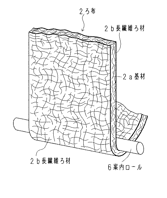
この発明の実施例を図面に基づき詳述すると、先ず、図1において、符号1は汚泥の濃縮槽であって、この濃縮槽1の液面上には、ろ布2を掛け回した圧搾装置3が配設してあり、この圧搾装置3はろ布2を逆W状に掛け回した三本の支持ロール4a、4b、4cと、中間の支持ロール4bにろ布2が反転上昇する部位に押し付けられた加圧ロール5とからなっている。これらの支持ロール4a、4b、4cに掛け回わされたろ布2が、濃縮槽1の槽底部に配設した案内ロール6に無端状に張設されており、加圧ロール5を電動機(図示せず)で駆動して、濃縮槽1に浸漬させたろ布2が、その一部分を濃縮槽1外に導出して循環走行させるようにしてある。圧搾装置3と案内ロール6に張設したろ布2は、図2に示すように、長繊維の不織布を基材2aとし、その両面に長繊維ろ材2bを熱融着した不織布から構成されており、その厚さは、吸水性を保つため、5〜10mmが好ましい。このろ布2を2.5〜5m/minで走行させることにより、固形物はろ材表面には付着しないで濃縮槽に残留して濃縮が行われる。濃度が高くなれば多少固形物がろ布2に付着しても前段の支持ロール4aでわずかに絞られたろ液が流下する際洗浄されて濃縮槽1に返送され、ろ液への固形物の混入を防止し、SSの回収率を高めることができる。そして、中間の支持ロール4bと加圧ロール5に挟持されて、ろ布2からろ液が分離され、ろ液はろ液トラフ7に回収される。加圧ロール5は支持ロール4bのろ布2が反転上昇する部位に押し付けられているので、脱水したろ液が回転するロールの表面を伝って、再びろ布2に吸込まれることがないようにしてある。ろ布2は後段の支持ロール4cに掛け回された後、濃縮槽1に浸漬されてろ液を吸水し、濃縮槽1外に導出され、濃縮槽1の汚泥は段々と濃縮される。符号8は原液の供給管であって、下水処理や廃水処理等で発生する無薬注の汚泥を供給ポンプ10で濃縮槽1に圧送するようにしてある。
【0007】
そして、上記走行自在に掛け回したろ布2は、図3に示すように、濃縮槽1に設置した複数の圧搾装置3と案内ロール6に連続的に掛け回し、このろ布2が無端状に周回する間に濃縮槽1への浸漬と濃縮槽1外への導出を繰り返しながら汚泥を濃縮させてもよく、汚泥の大容量処理が可能となるものである。そして、走行方向後方の加圧ロール5を駆動装置(図示せず)に連結すればよいものである。圧搾装置3で分離したろ液は複数のろ液トラフ7から集液トラフ9に集められて計量槽10に排出される。計量槽10には液面計11が設けてあり、分離されたろ液量が検知できるようにしてある。この液面計11の検知信号で、集液トラフ9と計量槽10との間に設けた開閉弁12と、計量槽10の槽底に設けた排液用の開閉弁13を開閉して、所定量となったろ液を排出するようにしてある。また、濃縮槽1にも液面計14が設けてあり、濃縮された汚泥の液面が検知できるようにしてあり、計測された濃縮汚泥を濃縮槽1の底部に設けた開閉弁15から排出するようにしてある。
【0008】
ろ材の吸水性の比較テストを行った。先ず、この発明のろ布である長繊維の不織布を基材としてその表面に長繊維を熱融着したろ材と、フェルト状ろ材、及び表面加工スポンジの三種類のろ材を100mm□の吸水ろ材サンプルとし、A処理場の活性余剰汚泥に浸漬して、ろ材単位容積当たりの吸水量を比較した。その結果、表1のように、この発明のろ布が最も吸水量が多く、吸水速度も速かった。
【0009】
【表1】
各ろ材をこの発明の図1の濃縮装置に装着し、ろ材走行速度2.5m/min、濃縮槽内汚泥濃度を約1%にして、能力の安定性並びに耐久性について試験した。その結果は表2及び表3のとおりであり、能力安定性とろ材の耐久性に優れていたのはこの発明のろ材であった。
【0011】
【表2】
【表3】
A処理場とB処理場の活性余剰汚泥について、無薬注にて濃縮試験を実施した。累積ろ液量の経時変化は、表4のように、ほぼ直線的に増加することが分かった。即ち、表5及び表6のように、濃縮倍率が直線的に増加しているにも関わらず、ろ過速度はほとんど低下せず、ほぼ一定に推移している。
【0014】
【表4】
【表5】
【表6】
また、ろ布走行速度を2.5m/minから5m/minに早くした場合、ほぼ走行速度に比例して、ろ過速度が上昇している。これは、汚泥の固液分離過程でろ材表面にろ過抵抗となるケーキが形成しないことに起因するものと考えられる。更に、圧搾装置で脱水する際、ろ材表面並びに内部のSSがろ液と共に排出され、目詰まり解消となっていることも安定したろ過が行える要因と考えられる。
【0018】
【発明の効果】
以上のように、この発明に係る汚泥の濃縮装置は、濃縮槽とロールのシンプルな構成に吸水性のあるろ材を張設して走行させるものであり、ろ布の吸水圧が低いので目詰まりすることがなく、汚泥も無薬注であり、ロールを走行させるエネルギーのみで短時間で高濃度汚泥が得られるものである。即ち、従来使用している織布のろ布では、表面に付着した濃縮液の剥離性が悪く、また、ろ布が短繊維の不織布では、表面に融着した短繊維層の劣化が激しく、短期間に表面層が剥離する欠点があった。しかも、これらの従来のろ布では、ろ布の駆動に大きな動力が必要な上、ろ布が目詰まりし易く再生が困難であったものであるが、この発明に係るろ布にあっては、長繊維の不織布を基材として、その表面に長繊維ろ材を熱融着したろ材であるので、吸水性能も長期にわたり高い値を維持でき、表面に融着した長繊維の剥離もなく、表面層の耐久性が大きいものである。そして、この発明に係る圧搾装置は、前段の支持ロールでわずかに絞られたろ液がろ布に付着した固形物をあらい流し、濃縮槽での固形物の回収率を高め、同時にろ布の目詰まりを防止する。そして、支持ロールに押し付けた加圧ロールが、ろ布が反転上昇する部位に設けてあるので、ろ布から分離されたろ液が再びろ布に吸引されることがないものである。
【図面の簡単な説明】
【図1】この発明に係る濃縮装置の摸式縦断側面図である。
【図2】この発明の濃縮装置に使用するろ布の一部の斜視図である。
【図3】この発明に係る濃縮装置の他の実施例の一部縦断斜視図である。
【符号の説明】
1 濃縮槽
1a 流路板
2 ろ布
2a 基材
2b 長繊維ろ材
3 圧搾装置
4a 支持ロール
4b 支持ロール
4c 支持ロール
5 加圧ロール
6 案内ロール[0001]
BACKGROUND OF THE INVENTION
The present invention relates to an apparatus for concentrating sludge generated at a sewage treatment plant, a wastewater treatment plant or the like, and in particular, a water-absorbing endless filter cloth disposed so as to run freely is immersed in the stock solution, and the absorbed filter cloth is absorbed. The present invention relates to an apparatus for concentrating a stock solution by dehydration outside a concentration tank.
[0002]
[Prior art]
The sludge generated in sewage treatment has deteriorated concentration due to an increase in organic matter, and it is difficult to obtain a predetermined concentration. For this reason, gravity concentration that separates the supernatant liquid by precipitating heavy sludge, centrifugal concentration that separates heavy sludge and liquid components using centrifugal force, or pressing up the sludge using compressed air for consolidation Floating concentration etc. taken out as a shape are used. However, running costs such as electric power and flocculant are increasing, and more economical concentration techniques are desired. Therefore, there are, for example, Japanese Utility Model Publication Nos. 4-27522 and 1-1526 proposed by the applicant of the present invention as a concentrator utilizing the absorption capacity of the filter cloth.
[0003]
[Problems to be solved by the invention]
However, conventional gravity concentrators and centrifugal concentrators require a large space and a large power as a device. In addition, in the case of using an endless filter cloth as in the above-mentioned conventional publication, the life of the filter cloth used directly affects the running cost, and the filter cloth used here can be a woven cloth or a non-woven cloth. The base fiber was used, and the same fiber was thermally fused on the surface to improve the peelability of the attached sludge. However, with a woven fabric that has been used in the past, the peelability of the concentrated liquid adhering to the surface was poor, and the filter fabric was prematurely clogged. In addition, when the filter cloth used is a short fiber non-woven fabric, the short fiber layer fused to the surface is severely deteriorated and the surface layer peels off in a short time. Moreover, a large amount of power is required to drive the filter cloth, and the filter cloth is easily clogged and difficult to regenerate. The present invention is an improvement of the concentrator proposed by the applicant in order to solve the above-described problems. ,
[0004]
[Means for Solving the Problems]
The gist of the present invention is that an endless filter cloth made of a water-absorbing material is immersed in a concentrating tank and disposed so as to be able to run, and a part of the filter cloth is led out of the concentrating tank, and the filter cloth is outside the tank. In the concentrating device provided with a squeezing device in the traveling part, the filter cloth is made of a nonwoven fabric in which a nonwoven fabric of long fibers is used as a base material, and a long fiber filter medium is thermally fused on the surface thereof. The upper filter cloth pressing device is composed of three support rolls in which the filter cloth is wound in an inverted W shape, and a pressure roll pressed against a portion where the filter cloth is inverted and raised by the intermediate support roll. Thus, the filter cloth hung around these support rolls is endlessly hung on a guide roll disposed at the bottom of the concentration tank, so that the filter cloth can run freely. Note that a plurality of filter cloth squeezing devices and guide rolls that are hung around may be installed in the concentration tank.
[0005]
DETAILED DESCRIPTION OF THE INVENTION
The present invention is configured as described above. When a filter cloth in which a long-fiber filter medium is heat-sealed on the surface of the non-woven fabric of the present invention is immersed in a concentrating tank and run, the capillary action of the filter cloth causes Water in the sludge is absorbed by the filter cloth surface. As for the filter cloth transferred to the outside of the concentration tank, the filtrate absorbed in the filter cloth surface is dehydrated by the squeezing device and is immersed again in the concentration tank. When the sludge concentration in the concentration tank increases, some SS adheres to the filter cloth surface, but when the filtrate slightly squeezed by the support roll flows down, the SS is recovered. And it spin-dry | dehydrates with a pressure roll, reverses a filter cloth with a support roller of a back | latter stage, and transfers the dehydrated filter cloth to a concentration tank. The filter cloth used in the concentrator is a non-woven fabric with a long-fiber filter medium layer fused to the surface of the nonwoven fabric of the base material, so there is no peeling due to deterioration, and the water absorption performance is maintained at a high value for a long time. The durability of the surface is also great. Further, since the water absorption pressure is low when the filter cloth absorbs water, the filter cloth is not clogged and the sludge can be continuously concentrated.
[0006]
【Example】
An embodiment of the present invention will be described in detail with reference to the drawings. First, in FIG. 1,
[0007]
And as shown in FIG. 3, the said filter cloth 2 hung around so that it can run freely hung around the several
[0008]
A comparative test of the water absorption of the filter medium was conducted. First, a 100 mm-square water-absorbing filter medium sample includes three types of filter media: a filter medium in which long fibers are non-woven fabric, which is the filter cloth of the present invention, and a long fiber is thermally fused to the surface, a felt-shaped filter medium, and a surface-treated sponge. Then, the amount of water absorption per unit volume of the filter medium was compared by immersing in the activated surplus sludge of the A treatment plant. As a result, as shown in Table 1, the filter cloth of the present invention had the largest water absorption amount and the high water absorption rate.
[0009]
[Table 1]
Each filter medium was mounted on the concentrator of FIG. 1 of the present invention, and the stability of the capacity and the durability were tested with a filter medium traveling speed of 2.5 m / min and a sludge concentration in the concentration tank of about 1%. The results are as shown in Table 2 and Table 3. The filter medium of the present invention was excellent in capacity stability and filter medium durability.
[0011]
[Table 2]
[Table 3]
About the activated surplus sludge of A processing plant and B processing plant, the concentration test was carried out by non-chemical injection. As shown in Table 4, it was found that the change with time of the cumulative filtrate amount increased almost linearly. That is, as shown in Tables 5 and 6, the filtration rate hardly decreased and remained almost constant, although the concentration rate increased linearly.
[0014]
[Table 4]
[Table 5]
[Table 6]
Further, when the filter cloth traveling speed is increased from 2.5 m / min to 5 m / min, the filtration speed increases almost in proportion to the traveling speed. This is considered to be caused by the fact that a cake that becomes filtration resistance is not formed on the surface of the filter medium in the solid-liquid separation process of sludge. Furthermore, when dewatering with a squeezing device, the fact that the surface of the filter medium and the internal SS are discharged together with the filtrate and clogging is eliminated is also considered to be a factor that enables stable filtration.
[0018]
【The invention's effect】
As described above, the sludge concentration apparatus according to the present invention is configured to run with a filter medium having water absorption in a simple configuration of a concentration tank and a roll, and is clogged because the water absorption pressure of the filter cloth is low. The sludge is also non-chemically poured, and high-concentration sludge can be obtained in a short time using only the energy for running the roll. That is, in the filter cloth of the woven cloth used conventionally, the peelability of the concentrated liquid adhering to the surface is bad, and in the non-woven cloth of the short fiber filter cloth, the deterioration of the short fiber layer fused to the surface is severe, There was a drawback that the surface layer peeled off in a short time. Moreover, these conventional filter cloths require a large amount of power to drive the filter cloth, and the filter cloth is easily clogged and difficult to regenerate. The filter medium is made of a long-fiber non-woven fabric as a base material, and a long-fiber filter medium is heat-sealed on the surface thereof. The layer is highly durable. The squeezing device according to the present invention allows the filtrate slightly squeezed by the support roll in the previous stage to flow away the solid matter adhering to the filter cloth, increasing the recovery rate of the solid substance in the concentration tank, and at the same time Prevent clogging. And since the pressurization roll pressed against the support roll is provided in the site | part where a filter cloth inverts and raises, the filtrate isolate | separated from the filter cloth is not attracted | sucked by the filter cloth again.
[Brief description of the drawings]
FIG. 1 is a vertical vertical side view of a concentrator according to the present invention.
FIG. 2 is a perspective view of a part of a filter cloth used in the concentration apparatus of the present invention.
FIG. 3 is a partially longitudinal perspective view of another embodiment of the concentrating device according to the present invention.
[Explanation of symbols]
DESCRIPTION OF
Claims (3)
Priority Applications (1)
| Application Number | Priority Date | Filing Date | Title |
|---|---|---|---|
| JP19865799A JP3636355B2 (en) | 1999-07-13 | 1999-07-13 | Sludge concentration equipment |
Applications Claiming Priority (1)
| Application Number | Priority Date | Filing Date | Title |
|---|---|---|---|
| JP19865799A JP3636355B2 (en) | 1999-07-13 | 1999-07-13 | Sludge concentration equipment |
Publications (2)
| Publication Number | Publication Date |
|---|---|
| JP2001025617A JP2001025617A (en) | 2001-01-30 |
| JP3636355B2 true JP3636355B2 (en) | 2005-04-06 |
Family
ID=16394882
Family Applications (1)
| Application Number | Title | Priority Date | Filing Date |
|---|---|---|---|
| JP19865799A Expired - Fee Related JP3636355B2 (en) | 1999-07-13 | 1999-07-13 | Sludge concentration equipment |
Country Status (1)
| Country | Link |
|---|---|
| JP (1) | JP3636355B2 (en) |
Families Citing this family (4)
| Publication number | Priority date | Publication date | Assignee | Title |
|---|---|---|---|---|
| JP4688332B2 (en) * | 2001-04-02 | 2011-05-25 | 新日鉄エンジニアリング株式会社 | Low concentration slurry dewatering equipment |
| CN110465125A (en) * | 2019-08-16 | 2019-11-19 | 徐州市久发工程机械有限责任公司 | A kind of lifting part processing and lubrication liquid filter device |
| CN112707620B (en) * | 2021-01-16 | 2022-12-27 | 宁波明州热电有限公司 | Sludge treatment system |
| CN112745000B (en) * | 2021-01-21 | 2021-07-30 | 黄河水利职业技术学院 | A kind of industrial sludge resource treatment system and its treatment method |
-
1999
- 1999-07-13 JP JP19865799A patent/JP3636355B2/en not_active Expired - Fee Related
Also Published As
| Publication number | Publication date |
|---|---|
| JP2001025617A (en) | 2001-01-30 |
Similar Documents
| Publication | Publication Date | Title |
|---|---|---|
| JP5608688B2 (en) | Method and apparatus for separating particles from a liquid | |
| JP3636355B2 (en) | Sludge concentration equipment | |
| JPS5850197A (en) | Dehydrator | |
| CN209575940U (en) | Box crawler belt Microfilter | |
| CN208195042U (en) | silicon chip cleaning device | |
| CN2910325Y (en) | Cylinder solid/liquid separator adopting synthetic resin thread | |
| CN207347269U (en) | A kind of rainwater treatment device | |
| JP3467736B2 (en) | Filtration device | |
| CN208144210U (en) | Ornamental fish tank roller type liquid dung separator | |
| JP2018094467A (en) | Drum type thickener | |
| JPS6135886B2 (en) | ||
| JP3504252B2 (en) | Sludge concentration method and apparatus | |
| CN220376551U (en) | Mining belt dewatering equipment | |
| JP3649382B2 (en) | Filtration equipment using floating media | |
| CN118978280A (en) | A MABR process denitrification treatment equipment that is easy to desilt | |
| CN2712922Y (en) | Sludge dewatering machine | |
| CN215352233U (en) | A sewage filter | |
| JPS6135816A (en) | Solid-liquid separation apparatus | |
| CN211025282U (en) | Separation sewage treatment plant | |
| CN1485494A (en) | Auxiliary dehydrating plant for vacuum wash hollander | |
| JPS6059002B2 (en) | Filtration concentration device | |
| JPH0123531Y2 (en) | ||
| JPS5837444Y2 (en) | Clarifying “filtration” device | |
| JPS6032947Y2 (en) | Belt press type dehydrator | |
| WO2024024383A1 (en) | Method and device for drying liquid-containing matter |
Legal Events
| Date | Code | Title | Description |
|---|---|---|---|
| TRDD | Decision of grant or rejection written | ||
| A01 | Written decision to grant a patent or to grant a registration (utility model) |
Free format text: JAPANESE INTERMEDIATE CODE: A01 Effective date: 20041217 |
|
| A61 | First payment of annual fees (during grant procedure) |
Free format text: JAPANESE INTERMEDIATE CODE: A61 Effective date: 20041230 |
|
| R150 | Certificate of patent or registration of utility model |
Free format text: JAPANESE INTERMEDIATE CODE: R150 |
|
| FPAY | Renewal fee payment (event date is renewal date of database) |
Free format text: PAYMENT UNTIL: 20080114 Year of fee payment: 3 |
|
| FPAY | Renewal fee payment (event date is renewal date of database) |
Free format text: PAYMENT UNTIL: 20090114 Year of fee payment: 4 |
|
| FPAY | Renewal fee payment (event date is renewal date of database) |
Free format text: PAYMENT UNTIL: 20100114 Year of fee payment: 5 |
|
| FPAY | Renewal fee payment (event date is renewal date of database) |
Free format text: PAYMENT UNTIL: 20100114 Year of fee payment: 5 |
|
| FPAY | Renewal fee payment (event date is renewal date of database) |
Free format text: PAYMENT UNTIL: 20110114 Year of fee payment: 6 |
|
| FPAY | Renewal fee payment (event date is renewal date of database) |
Free format text: PAYMENT UNTIL: 20120114 Year of fee payment: 7 |
|
| FPAY | Renewal fee payment (event date is renewal date of database) |
Free format text: PAYMENT UNTIL: 20130114 Year of fee payment: 8 |
|
| FPAY | Renewal fee payment (event date is renewal date of database) |
Free format text: PAYMENT UNTIL: 20140114 Year of fee payment: 9 |
|
| R250 | Receipt of annual fees |
Free format text: JAPANESE INTERMEDIATE CODE: R250 |
|
| LAPS | Cancellation because of no payment of annual fees |