JP3636655B2 - Electric dust collecting method and electric dust collecting device - Google Patents
Electric dust collecting method and electric dust collecting device Download PDFInfo
- Publication number
- JP3636655B2 JP3636655B2 JP2000367207A JP2000367207A JP3636655B2 JP 3636655 B2 JP3636655 B2 JP 3636655B2 JP 2000367207 A JP2000367207 A JP 2000367207A JP 2000367207 A JP2000367207 A JP 2000367207A JP 3636655 B2 JP3636655 B2 JP 3636655B2
- Authority
- JP
- Japan
- Prior art keywords
- voltage
- spark discharge
- control element
- power control
- spark
- Prior art date
- Legal status (The legal status is an assumption and is not a legal conclusion. Google has not performed a legal analysis and makes no representation as to the accuracy of the status listed.)
- Expired - Fee Related
Links
Images



Landscapes
- Electrostatic Separation (AREA)
Description
【0001】
【産業上の利用分野】
本発明は、排ガスなど気流中のダストを補集する電気集塵機の制御装置及び制御方法に係り、特に火花放電の頻発による荷電電圧の低下を抑制し得る電気集塵装置に関する。
【0002】
【従来の技術】
電気集塵においては、一般的に集塵電極と放電電極とからなる集塵部に印加される荷電電圧が高いとき集塵効率が高くなると言われており、このため集塵部の荷電電圧を火花放電が発生する寸前の高い電圧に維持できれば良いわけであるが、実際にはある程度の頻度にて火花放電が発生することを一つのパラメータとして、できるだけ火花放電が発生する電圧付近にて集塵部を荷電する時間が長くなるように、荷電電圧の制御が行われる。そして、火花放電が発生したときには集塵装置の荷電電圧が急速に低下する現象や、あるいは荷電電流が著しく増大する現象を捉えて集塵装置内部で発生する火花放電を検出し、火花放電が検出されたときには次のサイクルでの荷電を一旦停止して荷電電圧を低下させ、火花放電を消弧させることが行われている。
【0003】
図6により具体的に従来例を説明すると、電気集塵装置は、商用交流電源30と、その交流電圧を位相制御するための逆並列接続されたサイリスタなどからなる電力制御素子31と、昇圧変圧器32と、その2次側の交流電圧を整流する高電圧整流器33と、集塵極と放電極とからなる集塵部34と、荷電電圧検出手段35と、その検出電圧信号と基準信号とを演算して誤差信号を出力する回路であって、検出電圧信号が基準値より低くなったとき出力が極性反転して火花放電の発生の可能性を示す信号を発生する荷電電圧判定回路36と、集塵部34を流れる電流を検出する電流検出手段37と、その電流検出信号と基準信号とを演算して誤差信号を出力する回路であって、前記電流検出信号が基準値より低くなったとき出力が極性反転して、火花放電の発生の可能性を示す信号を発生する電流判定回路38と、電力制御素子31の位相制御を行う駆動信号を発生する位相制御回路39とからなる。
【0004】
次にこのような構成の電気集塵装置の動作を説明しながら、代表的な火花放電が発生したときの制御方法の一例について説明する。先ず、荷電電圧検出信号がその基準値よりも高いとき、また電流検出信号がその基準値よりも低いときには、それら信号により位相制御回路39は電力制御素子31に対して通常の位相制御を行う。荷電電圧検出信号がその基準値よりも低くなるとき、荷電電圧判定回路36の出力信号は極性反転し、その出力信号は火花放電の発生の可能性を示す信号となる。また、電流検出信号がその基準値よりも高くなるときには、電流判定回路38の出力信号は極性反転し、その出力信号は火花放電の発生の可能性を示す信号となる。そして、荷電電圧判定回路36と電流判定回路38の双方の出力信号の極性が反転すると、位相制御回路39は火花放電が発生したものと判定して、所定の期間、典型的には半サイクルだけ駆動信号を出力するのを止め、これにより半サイクルだけ一旦荷電中断となる。これに伴い荷電電圧は低下し、火花放電を消弧して、アーク放電に移行するのを防いでいた。そして、半サイクルだけ荷電停止をした後、50〜100ms程度の時間ソフトスタートにて電圧上昇速度θにて荷電電圧を上昇させる再荷電を行い、火花放電発生時の荷電電圧よりもΔV低い電圧に復帰させ、その後、電圧上昇速度θにて荷電電圧を徐々に上昇させていた。
【0005】
【発明が解決しようとする課題】
しかし、これまでの火花放電発生時の荷電制御は、火花放電からアーク放電への移行の可能性とは関係なく、火花放電の発生を検出したときには一様に荷電中断させて、荷電電圧を一旦ΔV降下させる火花制御を行っていた。そして、火花放電検出後の通常の荷電制御方法は、火花放電が発生した半サイクルの次の半サイクルでサイリスタの点弧を休止させて、その後は火花放電の再発および集塵部の静電容量への突入電流を防止するためソフトスタートにて荷電電圧を徐々に上昇させていた。
【0006】
特に、高抵抗ダストを含む石炭ボイラの排ガスなど火花放電の多発し易い電気集塵においては、前述のように火花放電が発生する度に荷電中断による荷電電圧の低下と再荷電時にソフトスタートが繰り返されると、集塵装置の荷電電圧の平均値が低下し、かなり集塵効率が低下するという問題があった。本発明はこのような問題点を解決し、荷電電圧の低下を抑制して荷電効率を従来に比べて向上させることを課題とする。
【0007】
【課題を解決するための手段】
前述の課題を解決するために、第1の発明は、交流電源からその交流電圧に対して遅れ位相の電流を供給し、集塵極と該集塵極に対向して配置された放電極との間に高電圧を印加して、それらの間を通過する気流に含まれるダストを捕集する電気集塵方法において、前記集塵極と前記放電極との間で火花放電の発生が検出されるとき、前記火花放電の発生を示す検出信号が、前記交流電源の交流電圧のゼロクロス時点から前記電力制御素子のオンの直前までの間に発生した場合には、前記電力制御素子の駆動を一旦中断させずに通常の制御を行って荷電を続行し、前記火花放電の発生を示す検出信号が、前記電力制御素子のオン時点から前記交流電源の交流電圧の次のゼロクロス時点までの間に発生した場合には、前記電力制御素子のオンを所定期間停止させて一旦荷電電圧を低下させることを特徴とする電気集塵方法を提供するものである。
【0008】
前述の課題を解決するために、第2の発明は、前記第1の発明において、前記電力制御素子の駆動信号がLレベルのときに火花放電の発生を示す検出信号が発生した場合には、前記電力制御素子の駆動を一旦中断させずに通常の制御を行って荷電を続行し、前記電力制御素子の駆動信号がHレベルのときに火花放電の発生を示す検出信号が発生した場合には、前記電力制御素子の駆動を所定期間中断させて一旦荷電電圧を低下させることを特徴とする電気集塵方法を提供するものである。
【0009】
前述の課題を解決するために、第3の発明は、交流電源と、該交流電源からの交流電力を制御する電力制御素子と、限流リアクトルと、昇圧変圧器と、該昇圧変圧器からの高電圧交流電圧を整流して直流に変換する高電圧整流器とを備え、集塵極と該集塵極に対向して配置された放電極とを含む集塵部を通過する気流に含まれるダストを捕集する電気集塵装置において、前記交流電源の電圧のゼロクロス点を検出するゼロクロス検出回路と、前記電力制御素子の導通を制御する駆動信号を発生する位相制御回路と、前記集塵極と前記放電極との間に火花放電が発生するとき火花放電検出信号を与える火花検出回路と、前記位相制御回路が出力する前記駆動信号がLレベルのときに火花放電の発生が検出された場合には、前記電力制御素子のオンを一旦停止させずに通常の制御を行って荷電を続行し、前記駆動信号がHレベルのときに前記火花放電の発生が検出された場合には前記電力制御素子の駆動を所定期間中断させて一旦荷電電圧を低下させる荷電制御回路とを備えたことを特徴とする電気集塵装置を提供するものである。
【0011】
【発明の実施の形態】
先ずこの発明を説明するに当たって、発明に至る考え方について説明する。(1)この発明は、アーク放電に移行しない火花放電が存在すればそのような火花放電については荷電停止や、その後のソフトスタートなどの火花制御を行う必要は無いはずであるという考え方から出発している。(2)したがって、先ず発生した火花放電がそのままの荷電状態を続けてもアーク放電に移行しないものがあるか否かを種々の実験から確認した。(3)その結果、発生した火花放電がそのままの荷電状態を続けてもアーク放電に移行しないアーク放電が存在し、少なくとも交流電源の交流電圧のゼロクロス時点近傍から電力制御素子のオンまでの間、つまり駆動信号が供給されていない期間に発生したものはこのようなアーク放電に移行しない火花放電であることを確認した。
【0012】
駆動信号が供給されておらず、交流電源の電圧の瞬時値がゼロクロス点又はその近傍まで低下しているときは、負荷側の集塵部において火花放電が発生しても電源電圧の瞬時値がゼロまで低下しているので、電源側から継続したエネルギ−の供給はできない。このことから、ゼロクロス点又はその近傍から電力制御素子の次のターンオンタイミングまでの間で発生した火花放電はアーク放電に移行する可能性が無いと言える。
【0013】
したがって、本発明は集塵極と放電極との間で火花放電が発生するとき、その火花放電の発生時点に従って選択的に、そのまま前記電力制御素子の駆動を継続させて荷電電圧を低下させる制御は行わず、あるいは前記電力制御素子の駆動を所定期間中断させて一旦荷電電圧を低下させる制御を行う電気集塵方法である。
【0014】
具体的には、本発明は集塵極と放電極を備える集塵部において発生する火花放電を検出し、その火花放電の発生が電力源となる交流電源の交流電圧の極性が変わる点、つまりゼロクロス点の近傍から逆並列接続したサイリスタのような電力制御素子のオン時点までの間に発生した場合、即ち電力制御素子の駆動信号が供給されていない期間に火花放電が発生しても、前記電力制御素子の駆動を一旦中断させずに通常の制御を行って荷電を続行するものである。そして、前記火花放電の発生が前記電力制御素子のオン時点から前記交流電源の交流電圧の次のゼロクロス時点までの間、つまり前記駆動信号が電力制御素子に供給されている期間に発生した場合には、従来と同様に前記電力制御素子の駆動を所定期間、例えば半サイクル中断させて一旦荷電電圧を低下させ、しかる後に再び前記電力制御素子をオンさせて荷電電圧を上昇させる。
【0015】
更に具体的には、前記電力制御素子の駆動信号を利用し、その駆動信号が発生している期間で発生した火花放電はアーク放電に移行する火花放電とし、前記駆動信号が発生していない期間で発生した火花放電はアーク放電に移行しない火花放電とする。そして、火花検出信号(火花放電が検出されたときHレベル)がHレベルであり、かつ前記駆動信号がHレベルのときだけ通常の火花制御(火花検出後の荷電停止、ソフトスタートによる再荷電)を行う。火花検出信号がHレベルであり、かつ前記駆動信号がLレベルのときは荷電中断を行わず、そのまま通常の荷電制御を続行する。このような新しい荷電制御を行う電気集塵方法により、集塵効率を向上させることができる。
【0016】
【実施例】
図1及び図2により、本発明の実施例について説明する。先ず、図1において、1は商用の交流電源、2は荷電制御盤、3は整流変圧回路、及び4は集塵電極と放電電極を備える集塵部である。荷電制御盤2は、交流電源1の電圧を検出する同期検出用変圧器5、逆並列接続されたサイリスタ又はIGBTなどからなる電力制御素子6、交流電源1の交流電圧のゼロクロス点を検出する通常の構成のゼロクロス検出回路7、ゼロクロス検出回路7を含み、電力制御素子6のオン、オフを制御する位相制御回路8、荷電制御回路9、火花検出回路10、その外に定電流制御回路、定電圧制御回路などを備えるがこれらについては図示するのを省略する。
【0017】
荷電制御回路9は、火花放電の発生が検出されるとき所定の電圧値だけ荷電電圧を下げる信号を出力する火花制御回路11、アーク放電に移行する可能性がある火花放電が検出されたときのみ、予め決めた所定の期間だけ、例えば半サイクルだけ荷電を中断して荷電電圧を一旦低下させ、荷電中断後は電力制御素子6の導通角を徐々に大きくして行くソフトスタート制御する荷電中断・ソフトスタート回路12、後述するように位相制御回路8における駆動信号と火花検出回路10からの火花放電検出信号とをAND論理してアーク放電に移行する可能性が高い火花放電検出信号だけを荷電中断・ソフトスタート回路12に通過させるAND回路14などを備える。
【0018】
火花検出回路10は、荷電電圧検出信号と基準電圧源15の基準電圧とを比較する第1の比較器16、集塵部4に流れる電流の検出信号と基準電流源17の基準値とを比較する第2の比較器18、比較器16と18の出力信号をAND論理するAND論理回路19からなり、荷電電圧検出信号がその基準電圧よりも小さく、かつ電流検出信号がその基準値よりも大きい場合に火花放電検出信号を出力する。
【0019】
整流変圧回路3は、限流リアクトル20、限流リアクトル20に1次巻線が接続された昇圧変圧器21、昇圧変圧器21の2次巻線に接続された高電圧整流器22、放電電極と接地間の電圧を分圧する分圧抵抗器23、24、及び集塵部4と高電圧整流器22との間に直列に接続されたシャント抵抗器25からなる。この実施例の回路では、限流リアクトル20は荷電電圧のリプル分の抑制と、短絡時の過電流を抑制するために設けられており、通常は昇圧変圧器21の短絡インピーダンスと合わせて30〜50%程度の%インダクタンスを持つように設定されている。このため、図2に示すように集塵部4の荷電電流波形は交流電源1の交流電圧波形に対して遅れ位相となる。本発明は、荷電電流が交流電源1の交流電圧に対して位相が遅れることを一つの条件として利用する。
【0020】
次に、このように構成された電気集塵装置の動作について説明する。荷電制御盤2の同期検出用変圧器5は交流電源1の交流電圧と同期した電圧を検出してゼロクロス検出回路7を含む位相制御回路8に送る。ゼロクロス検出回路7はこの電圧から交流電源1のゼロクロス点を検出してゼロクロス検出信号(D)を発生すると共に、荷電制御回路8からの制御信号に従ってゼロクロス時点を起点として電力制御素子6に点弧信号(C)を送出する。電力制御素子6により位相制御された交流電圧が整流変圧回路3に入力される。整流変圧回路3に加えられた交流電圧は昇圧変圧器21により昇圧され、高電圧整流器22により全波整流されて集塵部4に供給される。
【0021】
ここで位相制御回路8は図3に示すような回路構成になっており、次のように動作する。同期検出用変圧器5からの交流電圧は全波整流回路Reで整流され、その整流電圧は抵抗器R1とR2で分割される。分割された整流電圧は第1の比較器CM1で0Vよりも若干高い電圧に設定された基準電圧源Paの基準電圧と比較され、比較器CM1は前記分割された電圧がゼロになる度に図3(D)に示すようなゼロクロス検出信号(D)を発生する。一方、コンデンサC1は抵抗器R5を通して直流電源Pbから流れる電流で充電され、その両端の電圧はほぼ直線的に増大する。比較器CM1の出力に前記ゼロクロス検出信号(D)が現出すると、その度に抵抗器R3とR4を通してトランジスタTr1が順バイアスされてオンし、コンデンサC1をほぼゼロまで放電する。したがって、第2の比較器CM2の一方の入力端子には図3(A)に示す鋸歯状波信号(A1)が入力され、他方の入力端子には荷電制御回路9からの制御信号(A2)が入力される。制御信号(A2)は、火花制御回路11の出力信号、荷電中断・ソフトスタート回路12の出力信号、図示していない定電流制御回路や定電圧制御回路などの出力信号を合成したものからなり、それら出力信号により変化する。
【0022】
第2の比較器CM2は、図3(A)に示す鋸歯状波信号(A1)と制御信号(A2)とを比較し、鋸歯状波信号(A1)が制御信号(A2)よりも大きな期間でHレベルの駆動信号(B)を発生する。この駆動信号(B)は図2及び図4で示すように、電源電圧波形(a)のゼロクロス点から次の電力制御素子6のオン時点までの間がLレベルであり、ほぼ電力制御素子6のオン時点から次の電源電圧波形(a)のゼロクロス点までの間がHレベルである。また、この実施例では電力制御素子6がサイリスタであるので、駆動信号(B)はコンデンサC2及び抵抗器R6、R7で微分され、トランジスタTr2と抵抗器R8を通して急峻な波形の点弧信号Cに変換される。しかし、電力制御素子6がIGBT、あるいはMOSFETなどの場合には駆動信号(B)がそのままオン、オフ駆動に利用される。
【0023】
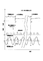
今、図2に示すように時刻t1で比較的大きな火花放電が発生したとする。火花放電の発生に伴い、荷電電圧の急激な低下や荷電電流の急激な増加をもたらし、この変化により火花検出回路10はHレベルの火花放電検出信号を出力する。しかし、この時刻t1では駆動信号(B)はLレベルとなっているのでAND論理回路14の出力はLレベルのままとなり、荷電中断・ソフトスタート回路12に荷電中断すための信号を送出しない。したがって、この期間に発生した火花放電はアーク放電に移行しないものとして、電力制御素子6の駆動を中断すること無くそのまま継続される。
【0024】
次に図2に示すように、駆動信号(B)がHレベルである時刻t2にて火花放電が発生したとすると、AND論理回路14の一方の入力である駆動信号(B)はHレベルで、他方の入力である火花放電検出信号もHレベルであるので、AND論理回路14の出力信号はHレベルである。この場合にはAND論理回路14から荷電中断・ソフトスタート回路12に信号が送出され、荷電中断・ソフトスタート回路12は従来と同様に所定の期間、例えば半サイクルだけ駆動信号(B)が供給されるのを禁止し、その所定の期間の経過後はソフトスタートモードで動作するよう指令を位相制御回路8へ与える。これに伴い、位相制御回路8は火花放電が検出された直後の半サイクルだけ駆動信号(B)を電力制御素子6に与えるのを中断し、しかる後には従来と同様に所定の小さなパルス幅から徐々にパルス幅の大きくなる駆動信号(B)を電力制御素子6に供給し、再荷電が行われる。
【0025】
なお、この実施例では火花放電の発生の際には駆動信号(B)のある無しには関係なく火花検出回路10から火花制御回路11に火花検出信号が送られ、火花制御回路11は荷電電圧を予め決めた設定電圧値だけ降下させ、その後所定の傾斜で上昇させる所定の荷電電圧制御を行う。
【0026】
次に図5に示す実施例は、駆動信号(B)がLレベルの期間に火花放電が発生した場合には、前述のようにその火花放電はアーク放電に移行しないものであるので、火花制御回路11の火花制御機能を禁止するものであり、図1の回路においてAND論理回路19の出力ではなく、AND論理回路14の出力を火花制御回路11の入力とする構成である。この回路構成では、駆動信号(B)がLレベルで、火花放電検出信号がHレベルのときだけ、AND論理回路14の出力がLレベルになり、この期間だけ火花制御回路11は動作せず、火花制御を行わない。したがって、火花放電が発生してもこの期間では、火花制御回路11は荷電電圧を予め決めた設定電圧値だけ降下させたり、その後所定の傾斜で上昇させる所定の荷電電圧制御を行わない。この実施例ではアーク放電に移行する可能性の無い火花放電が発生しても荷電電圧を予め決めた設定電圧値だけ降下させることがないから、さらに集塵効率を向上させることができるが、火花放電発生時に荷電電圧を予め決めた設定電圧値だけ降下させなくともアーク放電に移行する確率が低い条件の場合に適用される。
【0027】
なお、以上の実施例では電力制御素子の駆動信号をそのまま判別するための信号として用いたが、駆動信号と逆位相の信号を火花判別信号として形成し、その火花判別信号の発生している期間、つまり電源交流電圧のゼロクロス点から次の駆動信号が発生するまでの期間では、火花放電が発生してもアーク放電に移行する確率は十分に小さい安全期間とし、電力制御素子のオン駆動をそのまま継続しても良い。
【0028】
【発明の効果】
以上述べたように、本発明ではアーク放電に移行する可能性のある火花放電のみ従来と同様に荷電中断し、アーク放電に移行する可能性のない火花放電については荷電をそのまま続行するので、火花放電の多発時にも荷電電圧の低下を防止できるので集塵効率の低下を抑制できる。また、実現手段としては電源装置が既に備えている手段の組み合わせにより容易に実現できるので、コストアップになることは無い。
【図面の簡単な説明】
【図1】 本発明に係る電気集塵装置の火花制御装置の一実施例を示す。
【図2】 本発明に係る電気集塵装置の火花制御に係る信号波形を示す。
【図3】 本発明に係る電気集塵装置に用いられる位相制御回路の一実施例を示す。
【図4】 本発明に係る電気集塵装置の火花制御に係る信号波形を示す。
【図5】 本発明に係る電気集塵装置の火花制御装置の他の一実施例を示す。
【図6】 従来の電気集塵装置の火花検出装置の一例を示す。
【符号の説明】
1・・交流電源 2・・荷電制御盤
3・・整流変圧回路 4・・集塵部
5・・同期検出用変圧器 6・・電力制御素子
7・・ゼロクロス検出回路 8・・位相制御回路
9・・荷電制御回路 10・・火花検出回路
11・・火花制御回路 12・・荷電中断・ソフトスタート回路[0001]
[Industrial application fields]
The present invention relates to a control device and a control method for an electrostatic precipitator that collects dust in an airflow such as exhaust gas, and more particularly to an electrostatic precipitator that can suppress a decrease in charge voltage due to frequent spark discharge.
[0002]
[Prior art]
In electric dust collection, it is generally said that the dust collection efficiency increases when the charge voltage applied to the dust collection part consisting of the dust collection electrode and the discharge electrode is high. It is only necessary to maintain a high voltage just before the occurrence of a spark discharge, but in practice, the fact that a spark discharge occurs at a certain frequency is one parameter, and as much as possible near the voltage at which the spark discharge occurs. The charging voltage is controlled so that the time for charging the part becomes longer. Then, when a spark discharge occurs, it detects the spark discharge that occurs inside the dust collector by detecting the phenomenon that the charged voltage of the dust collector decreases rapidly or the phenomenon that the charging current increases significantly. When this is done, charging in the next cycle is temporarily stopped, the charging voltage is lowered, and the spark discharge is extinguished.
[0003]
A conventional example will be described in detail with reference to FIG. 6. The electrostatic precipitator includes a commercial
[0004]
Next, an example of a control method when a typical spark discharge occurs will be described while explaining the operation of the electrostatic precipitator having such a configuration. First, when the charge voltage detection signal is higher than the reference value and when the current detection signal is lower than the reference value, the
[0005]
[Problems to be solved by the invention]
However, the charge control at the time of occurrence of spark discharge so far, regardless of the possibility of the transition from spark discharge to arc discharge, when the occurrence of spark discharge is detected, the charge is interrupted uniformly and the charge voltage is temporarily set. Spark control was performed to lower ΔV. The normal charge control method after detecting the spark discharge is to stop the thyristor from firing in the next half cycle after the spark discharge has occurred, and then the recurrence of the spark discharge and the electrostatic capacity of the dust collecting part. The charge voltage was gradually increased by soft start to prevent inrush current.
[0006]
In particular, in the case of electrostatic dust collection, which is likely to generate spark discharge, such as coal boiler exhaust gas containing high-resistance dust, as described above, every time a spark discharge occurs, soft start is repeated at the time of charge voltage drop and recharge due to charge interruption. When this occurs, there is a problem that the average value of the charging voltage of the dust collector is lowered and the dust collection efficiency is considerably lowered. It is an object of the present invention to solve such problems and to improve the charging efficiency as compared with the prior art by suppressing a decrease in charging voltage.
[0007]
[Means for Solving the Problems]
To attain the above object, the first invention, the current of the delay phase and supplied to the AC voltage from an AC power source, a discharge electrode arranged opposite to the dust collection electrode and the dust collecting electrode a high voltage is applied between the, in electrostatic precipitation method of collecting dust contained in the air flow passing between them, the generation of spark discharge is detected between said discharge electrode and said collector Chirikyoku When the detection signal indicating the occurrence of the spark discharge is generated between the time when the AC voltage of the AC power supply is zero-crossed and immediately before the power control element is turned on, the power control element is temporarily driven. The charging is continued by performing normal control without interruption, and the detection signal indicating the occurrence of the spark discharge is generated between the time when the power control element is turned on and the time when the next zero cross of the AC voltage of the AC power supply is generated. If the power control element is turned on, There is provided an electrostatic precipitation method characterized by reducing the once charged voltage is stopped between regular.
[0008]
In order to solve the above-described problem, in a second invention, in the first invention , when a detection signal indicating the occurrence of spark discharge is generated when the drive signal of the power control element is at L level , When the normal control is performed without interrupting the driving of the power control element to continue charging, and a detection signal indicating the occurrence of spark discharge is generated when the drive signal of the power control element is at the H level. The electric dust collection method is characterized in that driving of the power control element is interrupted for a predetermined period to temporarily reduce the charging voltage.
[0009]
In order to solve the above-described problem, a third invention is an AC power source, a power control element that controls AC power from the AC power source, a current limiting reactor, a step-up transformer, and a step-up transformer. A high-voltage rectifier that rectifies high-voltage AC voltage and converts it to direct current, and includes dust contained in an airflow passing through a dust collecting portion that includes a dust collecting electrode and a discharge electrode disposed opposite to the dust collecting electrode. In the electrostatic precipitator that collects the electric power, a zero-cross detection circuit that detects a zero-cross point of the voltage of the AC power supply, a phase control circuit that generates a drive signal that controls conduction of the power control element, and the dust collection electrode, A spark detection circuit that provides a spark discharge detection signal when a spark discharge occurs between the discharge electrode and the discharge electrode when the occurrence of a spark discharge is detected when the drive signal output by the phase control circuit is at an L level; Of the power control element Once to continue the charge performs normal control without stopping, said drive signal is a predetermined time to interrupt the driving of the power control device in the case where generation of the spark discharge is detected at the H level An electrostatic precipitator comprising a charge control circuit for once reducing a charge voltage is provided.
[0011]
DETAILED DESCRIPTION OF THE INVENTION
First, in describing the present invention, the concept leading to the invention will be described. (1) This invention starts from the idea that if there is a spark discharge that does not shift to arc discharge, it is not necessary to perform spark control such as charge stop or subsequent soft start for such spark discharge. ing. (2) Therefore, it was confirmed from various experiments whether or not there was a spark discharge that did not shift to arc discharge even if the generated spark discharge continued to be charged as it was. (3) As a result, there is an arc discharge that does not shift to the arc discharge even if the generated spark discharge continues to be charged, and at least from the vicinity of the zero crossing point of the AC voltage of the AC power supply to the ON of the power control element, That is, it was confirmed that what occurred during the period when the drive signal was not supplied was such a spark discharge that did not shift to arc discharge.
[0012]
When the drive signal is not supplied and the instantaneous value of the AC power supply voltage drops to the zero crossing point or near the zero crossing point, the instantaneous value of the power supply voltage does not change even if a spark discharge occurs in the dust collector on the load side. Since it has decreased to zero, energy cannot be continuously supplied from the power supply side. From this, it can be said that there is no possibility that the spark discharge generated between the zero cross point or the vicinity thereof and the next turn-on timing of the power control element shifts to the arc discharge.
[0013]
Therefore, according to the present invention, when a spark discharge occurs between the dust collection electrode and the discharge electrode, the control is performed so as to reduce the charging voltage by continuing to drive the power control element as it is, according to the spark discharge occurrence time. Or an electric dust collection method in which the driving of the power control element is interrupted for a predetermined period and the charge voltage is once lowered.
[0014]
Specifically, the present invention detects a spark discharge generated in a dust collecting part including a dust collection electrode and a discharge electrode, and the polarity of the AC voltage of the AC power source that is the power source is the occurrence of the spark discharge, that is, Even if a spark discharge occurs in the period when the power control element such as a thyristor connected in reverse parallel from the vicinity of the zero cross point is generated, that is, even when a spark discharge occurs in a period in which the drive signal of the power control element is not supplied, Charging is continued by performing normal control without temporarily interrupting driving of the power control element. And, when the occurrence of the spark discharge occurs from the time when the power control element is turned on until the next zero crossing time of the AC voltage of the AC power supply, that is, when the drive signal is supplied to the power control element. In the same manner as in the prior art, the driving of the power control element is interrupted for a predetermined period, for example, a half cycle to temporarily lower the charging voltage, and then the power control element is turned on again to increase the charging voltage.
[0015]
More specifically, the spark discharge generated during a period in which the drive signal is generated using the drive signal of the power control element is a spark discharge that shifts to arc discharge, and the drive signal is not generated. The spark discharge generated in is a spark discharge that does not shift to arc discharge. And, when the spark detection signal (H level when spark discharge is detected) is H level and the drive signal is H level, normal spark control (charge stop after spark detection, recharge by soft start) I do. When the spark detection signal is at the H level and the drive signal is at the L level, the charge is not interrupted and the normal charge control is continued as it is. Dust collection efficiency can be improved by such an electric dust collection method that performs new charge control.
[0016]
【Example】
An embodiment of the present invention will be described with reference to FIGS. First, in FIG. 1, 1 is a commercial AC power source, 2 is a charge control panel, 3 is a rectifying transformer circuit, and 4 is a dust collecting unit including a dust collecting electrode and a discharge electrode. The
[0017]
The charge control circuit 9 outputs a signal that lowers the charge voltage by a predetermined voltage value when the occurrence of a spark discharge is detected, and only when a spark discharge that may shift to arc discharge is detected. Charge interruption for soft start control in which charging is temporarily reduced for a predetermined period of time, for example, half a cycle, and the charging voltage is temporarily reduced, and after the charging interruption, the conduction angle of the
[0018]
The spark detection circuit 10 compares the
[0019]
The
[0020]
Next, the operation of the electrostatic precipitator configured as described above will be described. The
[0021]
The
[0022]
The second comparator CM2 compares the sawtooth wave signal (A1) shown in FIG. 3A with the control signal (A2), and the period when the sawtooth wave signal (A1) is larger than the control signal (A2). The H level driving signal (B) is generated. As shown in FIGS. 2 and 4, the drive signal (B) is at the L level from the zero cross point of the power supply voltage waveform (a) to the next ON point of the
[0023]
Assume that a relatively large spark discharge occurs at time t1 as shown in FIG. Along with the occurrence of the spark discharge, a sudden decrease in the charging voltage and a rapid increase in the charging current are caused, and this change causes the spark detection circuit 10 to output an H level spark discharge detection signal. However, since the drive signal (B) is at the L level at time t1, the output of the AND
[0024]
Next, as shown in FIG. 2, if a spark discharge occurs at time t2 when the drive signal (B) is at the H level, the drive signal (B) that is one input of the AND
[0025]
In this embodiment, when a spark discharge occurs, a spark detection signal is sent from the spark detection circuit 10 to the
[0026]
Next, in the embodiment shown in FIG. 5, when a spark discharge occurs while the drive signal (B) is at the L level, the spark discharge does not shift to the arc discharge as described above. The spark control function of the
[0027]
In the above embodiment, the drive signal of the power control element is used as a signal for discriminating as it is, but a signal having a phase opposite to that of the drive signal is formed as a spark discrimination signal, and the period during which the spark discrimination signal is generated In other words, during the period from the zero cross point of the power supply AC voltage until the next drive signal is generated, the probability of transition to arc discharge is sufficiently small even if spark discharge occurs, and the on-drive of the power control element is left as it is. You may continue.
[0028]
【The invention's effect】
As described above, in the present invention, only the spark discharge that may shift to the arc discharge is interrupted as in the conventional case, and the charging is continued for the spark discharge that does not shift to the arc discharge. Since a decrease in charge voltage can be prevented even during frequent discharges, a decrease in dust collection efficiency can be suppressed. In addition, the implementation means can be easily realized by a combination of means already provided in the power supply apparatus, so that the cost is not increased.
[Brief description of the drawings]
FIG. 1 shows an embodiment of a spark control device for an electrostatic precipitator according to the present invention.
FIG. 2 shows signal waveforms related to spark control of the electrostatic precipitator according to the present invention.
FIG. 3 shows an embodiment of a phase control circuit used in the electrostatic precipitator according to the present invention.
FIG. 4 shows signal waveforms related to spark control of the electrostatic precipitator according to the present invention.
FIG. 5 shows another embodiment of the spark control device of the electrostatic precipitator according to the present invention.
FIG. 6 shows an example of a conventional spark detection device for an electrostatic precipitator.
[Explanation of symbols]
1 ....
Claims (3)
前記集塵極と前記放電極との間で火花放電の発生が検出されるとき、前記火花放電の発生を示す検出信号が、前記交流電源の交流電圧のゼロクロス時点から前記電力制御素子のオンの直前までの間に発生した場合には、前記電力制御素子の駆動を一旦中断させずに通常の制御を行って荷電を続行し、
前記火花放電の発生を示す検出信号が、前記電力制御素子のオン時点から前記交流電源の交流電圧の次のゼロクロス時点までの間に発生した場合には、前記電力制御素子のオンを所定期間停止させて一旦荷電電圧を低下させることを特徴とする電気集塵方法。 The current lag phase and supplied to the AC voltage from the AC power source applies a high voltage between the arranged the discharge electrode faces the dust collection electrode and the dust collecting electrode, passes between them In the electric dust collection method to collect dust contained in the airflow
When the occurrence of a spark discharge is detected between the dust collecting electrode and the discharge electrode, a detection signal indicating the occurrence of the spark discharge is activated when the power control element is turned on from the zero crossing point of the AC voltage of the AC power supply. If it occurs during the period immediately before, the normal control is performed without interrupting the drive of the power control element, and the charging is continued.
When the detection signal indicating the occurrence of the spark discharge is generated between the time when the power control element is turned on and the next zero cross time of the AC voltage of the AC power supply, the power control element is turned off for a predetermined period. An electric dust collection method characterized in that the charging voltage is once reduced.
前記電力制御素子の駆動信号がLレベルのときに火花放電の発生を示す検出信号が発生した場合には、前記電力制御素子の駆動を一旦中断させずに通常の制御を行って荷電を続行し、
前記電力制御素子の駆動信号がHレベルのときに火花放電の発生を示す検出信号が発生した場合には、前記電力制御素子の駆動を所定期間中断させて一旦荷電電圧を低下させることを特徴とする電気集塵方法。 In claim 1 ,
When the detection signal indicating the occurrence of spark discharge when the driving signal is at L-level of the power control device occurs, the charge to continue performing once normal control without interrupting the drive of the power control element ,
When the detection signal indicating the occurrence of spark discharge when the driving signal is at H level of the power control element is generated, and wherein reducing the once charged voltage by interrupting a predetermined period the driving of the power control element Electric dust collection method.
前記交流電源の電圧のゼロクロス点を検出するゼロクロス検出回路と、
前記電力制御素子の導通を制御する駆動信号を発生する位相制御回路と、
前記集塵極と前記放電極との間に火花放電が発生するとき火花放電検出信号を与える火花検出回路と、
前記位相制御回路が出力する前記駆動信号がLレベルのときに火花放電の発生が検出された場合には、前記電力制御素子のオンを一旦停止させずに通常の制御を行って荷電を続行し、前記駆動信号がHレベルのときに前記火花放電の発生が検出された場合には前記電力制御素子の駆動を所定期間中断させて一旦荷電電圧を低下させる荷電制御回路と、
を備えたことを特徴とする電気集塵装置。」AC power source, power control element for controlling AC power from AC power source, current limiting reactor, step-up transformer, and high-voltage rectifier that rectifies high-voltage AC voltage from step-up transformer and converts it to DC An electrostatic precipitator that collects dust contained in an airflow passing through a dust collecting portion including a dust collecting electrode and a discharge electrode disposed to face the dust collecting electrode ,
A zero cross detection circuit for detecting a zero cross point of the voltage of the AC power supply;
A phase control circuit for generating a drive signal for controlling conduction of the power control element;
A spark detection circuit to provide a spark discharge detection signal when the spark discharge occurs between the discharge electrode and the collector Chirikyoku,
If the occurrence of spark discharge is detected when the drive signal output from the phase control circuit is at L level, normal control is performed without temporarily stopping the power control element, and charging is continued. A charge control circuit for temporarily lowering a charge voltage by interrupting the drive of the power control element for a predetermined period when occurrence of the spark discharge is detected when the drive signal is at an H level ;
An electric dust collector characterized by comprising: "
Priority Applications (1)
| Application Number | Priority Date | Filing Date | Title |
|---|---|---|---|
| JP2000367207A JP3636655B2 (en) | 2000-12-01 | 2000-12-01 | Electric dust collecting method and electric dust collecting device |
Applications Claiming Priority (1)
| Application Number | Priority Date | Filing Date | Title |
|---|---|---|---|
| JP2000367207A JP3636655B2 (en) | 2000-12-01 | 2000-12-01 | Electric dust collecting method and electric dust collecting device |
Publications (2)
| Publication Number | Publication Date |
|---|---|
| JP2002166197A JP2002166197A (en) | 2002-06-11 |
| JP3636655B2 true JP3636655B2 (en) | 2005-04-06 |
Family
ID=18837671
Family Applications (1)
| Application Number | Title | Priority Date | Filing Date |
|---|---|---|---|
| JP2000367207A Expired - Fee Related JP3636655B2 (en) | 2000-12-01 | 2000-12-01 | Electric dust collecting method and electric dust collecting device |
Country Status (1)
| Country | Link |
|---|---|
| JP (1) | JP3636655B2 (en) |
Families Citing this family (3)
| Publication number | Priority date | Publication date | Assignee | Title |
|---|---|---|---|---|
| JP4492298B2 (en) * | 2004-11-01 | 2010-06-30 | パナソニック株式会社 | Spark detection circuit for electric dust collector |
| WO2017099776A1 (en) * | 2015-12-10 | 2017-06-15 | General Electric Technology Gmbh | Method and system for data capture for electrostatic precipitator control |
| JP7222784B2 (en) * | 2019-03-28 | 2023-02-15 | 住友重機械工業株式会社 | Pulse charging device, control method thereof, and electrostatic precipitator |
-
2000
- 2000-12-01 JP JP2000367207A patent/JP3636655B2/en not_active Expired - Fee Related
Also Published As
| Publication number | Publication date |
|---|---|
| JP2002166197A (en) | 2002-06-11 |
Similar Documents
| Publication | Publication Date | Title |
|---|---|---|
| JP2641164B2 (en) | Electric precipitator power supply | |
| US9099925B2 (en) | Switching power supply with circuit to control turn on timing of switching element | |
| CN201613182U (en) | Corona blue light dust collector | |
| KR0137389B1 (en) | Electric dust collector | |
| JP3623181B2 (en) | High voltage semiconductor switch device and high voltage generator | |
| JP2016010210A (en) | DC power supply device, inverter drive device, and air conditioner using the same | |
| JP3636655B2 (en) | Electric dust collecting method and electric dust collecting device | |
| CN109759677B (en) | Welding power supply device | |
| JP3708468B2 (en) | Power supply | |
| CN110494248B (en) | Welding power supply unit | |
| JP2019217544A (en) | Weld power supply | |
| JP3631158B2 (en) | Electric dust collecting power supply device and control method thereof | |
| JP2018187645A (en) | Welding power supply device | |
| JPH11144860A (en) | High frequency heating equipment | |
| JP3643062B2 (en) | Power supply for electric dust collection | |
| JP3822842B2 (en) | Power supply device for arc machining | |
| JPH0631680Y2 (en) | Discharge lamp lighting device | |
| EP0119584B1 (en) | Lighting circuit for electric discharge lamp | |
| KR200194413Y1 (en) | Battery charger of zero switching type | |
| JPH11333323A (en) | Method for preventing glow discharge in electric dust collector | |
| JP2019089093A (en) | Welding power supply | |
| JP3170833B2 (en) | Power supply for arc machining | |
| JPS5924374Y2 (en) | electrostatic precipitator | |
| JP2599623B2 (en) | Charging device | |
| JP3463965B2 (en) | Plasma arc processing equipment |
Legal Events
| Date | Code | Title | Description |
|---|---|---|---|
| A977 | Report on retrieval |
Free format text: JAPANESE INTERMEDIATE CODE: A971007 Effective date: 20040921 |
|
| A131 | Notification of reasons for refusal |
Free format text: JAPANESE INTERMEDIATE CODE: A131 Effective date: 20040927 |
|
| A521 | Written amendment |
Free format text: JAPANESE INTERMEDIATE CODE: A523 Effective date: 20041126 |
|
| RD02 | Notification of acceptance of power of attorney |
Free format text: JAPANESE INTERMEDIATE CODE: A7422 Effective date: 20041126 |
|
| TRDD | Decision of grant or rejection written | ||
| A01 | Written decision to grant a patent or to grant a registration (utility model) |
Free format text: JAPANESE INTERMEDIATE CODE: A01 Effective date: 20050104 |
|
| A61 | First payment of annual fees (during grant procedure) |
Free format text: JAPANESE INTERMEDIATE CODE: A61 Effective date: 20050105 |
|
| R150 | Certificate of patent or registration of utility model |
Free format text: JAPANESE INTERMEDIATE CODE: R150 Ref document number: 3636655 Country of ref document: JP Free format text: JAPANESE INTERMEDIATE CODE: R150 |
|
| S533 | Written request for registration of change of name |
Free format text: JAPANESE INTERMEDIATE CODE: R313533 |
|
| R350 | Written notification of registration of transfer |
Free format text: JAPANESE INTERMEDIATE CODE: R350 |
|
| R250 | Receipt of annual fees |
Free format text: JAPANESE INTERMEDIATE CODE: R250 |
|
| FPAY | Renewal fee payment (event date is renewal date of database) |
Free format text: PAYMENT UNTIL: 20100114 Year of fee payment: 5 |
|
| R250 | Receipt of annual fees |
Free format text: JAPANESE INTERMEDIATE CODE: R250 |
|
| FPAY | Renewal fee payment (event date is renewal date of database) |
Free format text: PAYMENT UNTIL: 20100114 Year of fee payment: 5 |
|
| FPAY | Renewal fee payment (event date is renewal date of database) |
Free format text: PAYMENT UNTIL: 20110114 Year of fee payment: 6 |
|
| R250 | Receipt of annual fees |
Free format text: JAPANESE INTERMEDIATE CODE: R250 |
|
| FPAY | Renewal fee payment (event date is renewal date of database) |
Free format text: PAYMENT UNTIL: 20110114 Year of fee payment: 6 |
|
| FPAY | Renewal fee payment (event date is renewal date of database) |
Free format text: PAYMENT UNTIL: 20120114 Year of fee payment: 7 |
|
| R250 | Receipt of annual fees |
Free format text: JAPANESE INTERMEDIATE CODE: R250 |
|
| FPAY | Renewal fee payment (event date is renewal date of database) |
Free format text: PAYMENT UNTIL: 20120114 Year of fee payment: 7 |
|
| FPAY | Renewal fee payment (event date is renewal date of database) |
Free format text: PAYMENT UNTIL: 20130114 Year of fee payment: 8 |
|
| R250 | Receipt of annual fees |
Free format text: JAPANESE INTERMEDIATE CODE: R250 |
|
| FPAY | Renewal fee payment (event date is renewal date of database) |
Free format text: PAYMENT UNTIL: 20130114 Year of fee payment: 8 |
|
| FPAY | Renewal fee payment (event date is renewal date of database) |
Free format text: PAYMENT UNTIL: 20140114 Year of fee payment: 9 |
|
| R250 | Receipt of annual fees |
Free format text: JAPANESE INTERMEDIATE CODE: R250 |
|
| S111 | Request for change of ownership or part of ownership |
Free format text: JAPANESE INTERMEDIATE CODE: R313115 |
|
| R350 | Written notification of registration of transfer |
Free format text: JAPANESE INTERMEDIATE CODE: R350 |
|
| R250 | Receipt of annual fees |
Free format text: JAPANESE INTERMEDIATE CODE: R250 |
|
| R250 | Receipt of annual fees |
Free format text: JAPANESE INTERMEDIATE CODE: R250 |
|
| S111 | Request for change of ownership or part of ownership |
Free format text: JAPANESE INTERMEDIATE CODE: R313117 |
|
| R350 | Written notification of registration of transfer |
Free format text: JAPANESE INTERMEDIATE CODE: R350 |
|
| R250 | Receipt of annual fees |
Free format text: JAPANESE INTERMEDIATE CODE: R250 |
|
| S531 | Written request for registration of change of domicile |
Free format text: JAPANESE INTERMEDIATE CODE: R313531 |
|
| R350 | Written notification of registration of transfer |
Free format text: JAPANESE INTERMEDIATE CODE: R350 |
|
| S111 | Request for change of ownership or part of ownership |
Free format text: JAPANESE INTERMEDIATE CODE: R313115 |
|
| R350 | Written notification of registration of transfer |
Free format text: JAPANESE INTERMEDIATE CODE: R350 |
|
| R250 | Receipt of annual fees |
Free format text: JAPANESE INTERMEDIATE CODE: R250 |
|
| R250 | Receipt of annual fees |
Free format text: JAPANESE INTERMEDIATE CODE: R250 |
|
| R250 | Receipt of annual fees |
Free format text: JAPANESE INTERMEDIATE CODE: R250 |
|
| S533 | Written request for registration of change of name |
Free format text: JAPANESE INTERMEDIATE CODE: R313533 |
|
| R350 | Written notification of registration of transfer |
Free format text: JAPANESE INTERMEDIATE CODE: R350 |
|
| LAPS | Cancellation because of no payment of annual fees |