JP3638325B2 - Amusement machine lighting equipment - Google Patents
Amusement machine lighting equipment Download PDFInfo
- Publication number
- JP3638325B2 JP3638325B2 JP30926994A JP30926994A JP3638325B2 JP 3638325 B2 JP3638325 B2 JP 3638325B2 JP 30926994 A JP30926994 A JP 30926994A JP 30926994 A JP30926994 A JP 30926994A JP 3638325 B2 JP3638325 B2 JP 3638325B2
- Authority
- JP
- Japan
- Prior art keywords
- light
- game board
- electrode
- plate
- lead wire
- Prior art date
- Legal status (The legal status is an assumption and is not a legal conclusion. Google has not performed a legal analysis and makes no representation as to the accuracy of the status listed.)
- Expired - Fee Related
Links
- WABPQHHGFIMREM-UHFFFAOYSA-N lead(0) Chemical compound [Pb] WABPQHHGFIMREM-UHFFFAOYSA-N 0.000 claims description 36
- 238000005034 decoration Methods 0.000 claims description 34
- 238000005401 electroluminescence Methods 0.000 claims description 34
- 238000007639 printing Methods 0.000 claims description 29
- 239000004020 conductor Substances 0.000 claims description 20
- 239000000853 adhesive Substances 0.000 claims description 14
- 230000001070 adhesive effect Effects 0.000 claims description 13
- 238000005286 illumination Methods 0.000 claims description 9
- 238000009413 insulation Methods 0.000 claims description 7
- 239000011347 resin Substances 0.000 description 8
- 229920005989 resin Polymers 0.000 description 8
- 238000004519 manufacturing process Methods 0.000 description 6
- 238000000034 method Methods 0.000 description 6
- 230000000694 effects Effects 0.000 description 5
- 230000003287 optical effect Effects 0.000 description 5
- 241000722921 Tulipa gesneriana Species 0.000 description 3
- 239000003086 colorant Substances 0.000 description 3
- 239000000463 material Substances 0.000 description 3
- OAICVXFJPJFONN-UHFFFAOYSA-N Phosphorus Chemical compound [P] OAICVXFJPJFONN-UHFFFAOYSA-N 0.000 description 2
- 230000005540 biological transmission Effects 0.000 description 2
- 238000003780 insertion Methods 0.000 description 2
- 230000037431 insertion Effects 0.000 description 2
- 239000004819 Drying adhesive Substances 0.000 description 1
- 241000196324 Embryophyta Species 0.000 description 1
- 241001465754 Metazoa Species 0.000 description 1
- 241000238413 Octopus Species 0.000 description 1
- 239000004820 Pressure-sensitive adhesive Substances 0.000 description 1
- BQCADISMDOOEFD-UHFFFAOYSA-N Silver Chemical compound [Ag] BQCADISMDOOEFD-UHFFFAOYSA-N 0.000 description 1
- 239000002390 adhesive tape Substances 0.000 description 1
- 230000000903 blocking effect Effects 0.000 description 1
- 239000002131 composite material Substances 0.000 description 1
- 238000010586 diagram Methods 0.000 description 1
- 230000005489 elastic deformation Effects 0.000 description 1
- 238000005516 engineering process Methods 0.000 description 1
- 238000007667 floating Methods 0.000 description 1
- 230000001678 irradiating effect Effects 0.000 description 1
- 238000004020 luminiscence type Methods 0.000 description 1
- 239000011120 plywood Substances 0.000 description 1
- 238000003825 pressing Methods 0.000 description 1
- 230000001681 protective effect Effects 0.000 description 1
- 229910052709 silver Inorganic materials 0.000 description 1
- 239000004332 silver Substances 0.000 description 1
- 239000007790 solid phase Substances 0.000 description 1
- 238000002834 transmittance Methods 0.000 description 1
- 239000002023 wood Substances 0.000 description 1
Images


Landscapes
- Pinball Game Machines (AREA)
Description
【0001】
【産業上の利用分野】
この発明はパチンコ機、スロットマシンなどの遊技機に用いられ、特にプレート状やフィルム状など薄物の電飾装置に関する。
【0002】
【従来の技術】
パチンコ機にあっては、ストップランプ、賞球ランプ、入賞口、風車、ランプ風車、センタ役物、大入賞口、バンド飾りおよびサイドランプなど多種類の飾り物を、遊技板の前面に存在するセル板上に取り付けてあり、これらの飾り物のうちで、発光表示による電飾効果を出す場合には、飾り物の前面に位置する意匠パターンの裏側に電球または発光ダイオード(LED)などの光源を配置し、この光源に遊技板の裏面に取り付けた電気ユニットから電力を供給し、光源を点灯し、この光源から発光した光を飾り物の意匠パターンに照射して透過することによって、飾り物の意匠パターンを所定色に発光表示している。
【0003】
【発明が解決しようとする課題】
一般に、電球や発光ダイオードなどの光源は、例えば厚さ0.5ミリメートル、面積20平方ミリメートルなどのように、薄くて広い面積を有し、しかも動植物や乗り物などの意匠パターンを有する単体に構成するのはむずかしい。
【0004】
このため、上記飾り物の内部に電球などの光源を配置する複雑な構造を取らなければならないうえ、遊技球の通り道の邪魔とならないように電球を設置する必要から、電球設置に制約が多く、飾り物の前面に適切に設けた意匠パターンを鮮明な色に発光表示するのはほとんど不可能に近かった。
【0005】
そこで、この発明は、遊技球の道筋に支障を招くことなく、飾り物の前面を鮮明な色に発光表示することができる電飾装置およびその製造方法を提供するものである。
【0006】
【課題を解決するための手段】
この発明の電飾装置は、遊技板の前面に取り付けられる飾り物の遊技板の前面から前側に離れた前面に設けられ、遊技板の裏面からの電力供給により発光表示する遊技機の電飾装置であって、飾り物の前面とほぼ同じ外形を有する表示プレート、表示プレートの裏面に付設されたエレクトロルミネッセンスプレート、エレクトロルミネッセンスプレートの裏面に付設された接着剤および剥離紙から構成され、表示プレートが、光透過性樹脂板の裏面に光透過性を有するデサイン化された意匠印刷、意匠印刷の表示部以外の部分に遮光部を構成する遮光印刷、意匠印刷の遮光印刷抜きされた部分で構成された表示部を備えた構成であり、エレクトロルミネッセンスプレートが、透明電極、背面電極、透明電極と背面電極との間に設けられた発光層、透明電極と背面電極とから一体に延びて飾り物を経由して遊技板の裏面に引き出される引き出し線、透明電極と背面電極との絶縁を保持するとともに透明電極の引き出し線と背面電極からの引き出し線との絶縁を保持する絶縁層とを備えたことを最も特徴とする。この発明の電飾装置にあっては、遊技板の裏面に引き出された透明電極からの引き出し線の端部は、絶縁層の一表面が剥ぎ取られて引き出し線を露出した接続端子部を構成し、遊技板の裏面に引き出された背面電極からの引き出し線の端部は、絶縁層の一表面が剥ぎ取られて引き出し線を露出した接続端子部を構成し、飾り物における遊技板の裏側に突出した背部ユニットにはクリップが設けられ、遊技板の裏面には、エレクトロルミネッセンスプレートへの電力供給用の電気ユニットが設けられ、電気ユニットから延びる電気ユニット側フラットケーブルには露出する複数の導電体を有する接続端子部が設けられ、電気ユニット側フラットケーブルにおける接続端子部の複数の導電体と透明電極からの引き出し線の接続端子部に露出する導電体と背面電極からの引き出し線の接続端子部に露出する導電体とが互いにその極性を間違えないように重ね合わせられたままクリップの相対峙する二つの挟持片の間の隙間に上方より挿入されることによってクリップの相対峙する二つの挟持片の弾性押圧下で重ね合わせに接続されてもよい。
【0007】
【作用】
この発明の電飾装置によれば、剥離紙を剥がし、接着剤を飾り物の遊技板の前面から前側に離れる前面に押し付けることによって、電飾装置が飾り物の遊技板の前面から前側に離れる前面に取り付けられる。エレクトロルミネッセンスプレートの発光層が電気的に発光した場合には、エレクトロルミネッセンスプレートの発光層の発光色と表示プレートの光透過性を有するデサイン化された意匠印刷からなる表示部の発光色とが混合した色で発光表示し、エレクトロルミネッセンスプレートの発光層が電気的に発光していない場合はには、表示プレートの光透過性を有するデサイン化された意匠印刷からなる表示部の発光色による表示が得られる。また、電気ユニット側フラットケーブルにおける複数の導電体と透明電極からの引き出し線における導電体と背面電極からの引き出し線における導電体とを互いにその極性を間違えないように重ね合わたままクリップの相対峙する二つの挟持片の間の隙間に挿入することによって、電気ユニット側フラットケーブルとエレクトロルミネッセンスプレートの引き出し線とがクリップの弾性作用下で接続される。
【0008】
【実施例】
以下、この発明の一実施例を図面とともに詳述する。
【0009】
図1は実施例の電飾装置を示す図、図2は同電飾装置の製造方法を示すフローチャート、図3は実施例のゲージ盤を示す正面図、図4は実施例の電飾装置をゲージ盤上の飾り物に取り付けた断面図、図5は実施例の電飾装置の引き出し線と電気ユニット側フラットケーブルとの接続を示す断面図、図6は引き出し線の接続端子部および電気ユニット側フラットケーブルの接続端子部を重ね合わせる状態を示す平面図である。
【0010】
図3において、遊技板20はほぼ方形のベニヤ板の前面に図外のデザイン図の印刷されたセル板を接着し、セル板上には図外の発射装置から発射された遊技球を遊技領域に誘導するバンド21を設置し、このバンド21内における遊技領域の中央部にはセンタ役物22、その周囲の遊技領域には左右のランプ風車23、左右の入賞口24、左右の電動チューリップ25、下部の始動口26、最下部のアウト口27および全体に点在する多数の遊技釘28それぞれを取り付け、バンド21外における非遊技領域の上部には賞球ランプ29およびストップランプ30を取り付け、以て、遊技板20がゲージ盤となる。
【0011】
上記バンド21、入賞口24、アウト口27および遊技釘28以外の飾り物、つまりセンタ役物22、ランプ風車23、電動チューリップ25、始動口26、賞球ランプ29およびストップランプ30などの飾り物は、それぞれの網目模様を描いた前面にカラフルな色彩およびデザインされた薄物の電飾装置1を有する。
【0012】
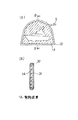
例えば、センタ役物22に用いられた電飾装置1を例として図1を参照して説明すると、この電飾装置1は、大まかには、A図に示す正面図ではセンタ役物22の上部前面とほぼ同じ外形を有する意匠パターン2、意匠パターン2中の表示部3、意匠パターン2中の表示部3以外の部分である遮光部4、および引き出し線5を備え、B図に示す断面図では表示プレート6、表示プレート6の裏面に付設されたエレクトロルミネッセンスプレート7、エレクトロルミネッセンスプレート7の裏面に付設された接着剤8および剥離紙9から構成される。
【0013】
表示プレート6は、光透過性樹脂板6aの裏面に光透過性を有する単色または複数色からなる例えば煙りを吐く船のようなデサイン化された意匠印刷6bを備え、この意匠印刷6bの表示部3以外の部分に遮光印刷6cを備え、意匠印刷6bの遮光印刷抜きされた部分が表示部3となり、遮光印刷6cが遮光部4となり、この遮光印刷6cは例えば宝くじにおいてコインなどで剥がす部分に使用されている銀色の光を遮る性質を有する素材にて構成される。
【0014】
エレクトロルミネッセンスプレート7は透明電極7aと背面電極7bとの間に発光層7cを有し、透明電極7aおよび背面電極7bは意匠パターン2および引き出し線5を含む正面形状を備え、発光層7cは意匠パターン2より少し小さなA図に点線で示す正面形状を有し、その発光層7cの外縁には透明電極7aと背面電極7bとの絶縁を保持する絶縁層7dを備え、発光層7cは樹脂バインダ中に80〜90ウエイトパーセントの比率で蛍光体を分散し、透明電極7aと背面電極7bとの間に電圧を加えることによって、発光層7c中の蛍光体が所定色に発光し、その発光が透明電極7aを透過して発光表示する(日経BP社;NIKKEI MATERIALS&TECHNOLOGY;94.1(no.137参照)。
【0015】
なお図1のA図中の符号10は引き出し線5を含む意匠パターン2を型抜き成形する前の原型(オリジナルパターン)を示す。
【0016】
上記絶縁層7dは引き出し線5の部分にも存在するが、この部分では透明電極7aおよび背面電極7bは絶縁層7d中に並列配置に敷設され、引き出し線5の端部において、絶縁層7dの一表面が剥ぎ取られて透明電極7aおよび背面電極7bが露出し、絶縁層7dの他表面が露出した透明電極7aおよび背面電極7bに裏打ちされた接続端子部を構成する(図6参照)。
【0017】
この電飾装置1の製造工程について図2を用いて説明すると、原型10の光透過性樹脂板6aを構成する透明フィルムの裏面に意匠印刷6bを行い、この意匠印刷6bの表示部3以外の部分に遮光印刷6cを行い、この透明フィルム6aの遮光印刷6bおよび意匠印刷6c側の裏面に原型10のエレクトロルミネッセンスプレート(ELプレート)7を熱圧着し、このエレクトロルミネッセンスプレート7の裏面に接着剤8および剥離紙9を含むのり付けを行い、これらの接着剤8と剥離紙9とエレクトロルミネッセンスプレート7と意匠印刷6bと遮光印刷6cおよび透明フィルム6aからなる原型10の積層体を引き出し線5を含む意匠パターン2に型抜き成形することによって、図1のA図に実線で示す外形を有する電飾装置1が完成する。
【0018】
この実施例では、エレクトロルミネッセンスプレートメーカ(製造業者)が図1のA図に点線で示す形状の発光層7a、つまり型抜きされる意匠パターン2よりも少し小さな形状の発光層7aを有する仮想線示の原型10のエレクトロルミネッセンスプレート7を製造して印刷メーカに納入する。
【0019】
印刷メーカは、原型10の透明フィルム6aに意匠印刷6bおよび遮光印刷6cを行い、その透明フィルム6aの裏面を上記購入したエレクトロルミネッセンスプレート7の透明電極7aに重ね合わせて熱圧着して、透明フィルム6aとエレクトロルミネッセンスプレート7とをその間に意匠印刷6bおよび遮光印刷6c介在した状態で一体に結合し、そのエレクトロルミネッセンスプレート7の背面電極7cの裏面に接着剤8を層状に形成し、その接着剤8の裏面に剥離紙9を付設した後に、プレス機械などで原型10から図1のA図に実線で示す引き出し線5を含む意匠パターン2の型抜きを行うことで、意匠パターン2の表示部3を構成する絵が意匠パターン2の遮光部4と位置ずれを発生することが無く、薄物の電飾装置1を完成して飾り物メーカに納入する。
【0020】
飾り物メーカは、電飾装置1から剥離紙9を剥がすとともに、電飾装置1の引き出し線5を図4に示す組み立ての完了したセンタ役物22のベース22aに形成された貫通孔22bに前面より挿入し、電飾装置1の裏面に露出した接着剤8をセンタ役物22の前面22cに重ね合わせて押圧し、薄物の電飾装置1をセンタ役物22の前面22cに取り付けた後に、パチンコ機メーカに納入する。
【0021】
この飾り物メーカで電飾装置1の付設されたセンタ役物22をパチンコ機メーカに出荷するのに先駆けて、貫通孔22bからベース22aの裏面に引き出された引き出し線5の中間部をセンタ役物22の遊技板20の裏側に突出配置される背部ユニット22dの側面に図外の接着テープにて添付しておけば、後述するパチンコ機メーカでのセンタ役物22の組み付け性が向上する。
【0022】
パチンコ機メーカでは、飾り物の遊技板20への組み付け工程にて、電飾装置1の付いたセンタ役物22を遊技板20に取り付ける場合、図4に示すように、センタ役物22の背部ユニット22dおよびベース22aの裏面より出ている引き出し線5を遊技板20に形成されたセンタ役物用開口20aに前面より挿入し、ベース22aの周縁をセンタ役物用開口20aまわりの遊技板20の前面に位置する図外のセル板に当接し、ベース22aの周縁に形成され図外のねじ挿入用の貫通孔より木ねじのようなねじ釘を遊技板20に形成された下穴を介して締結することにより、センタ役物22を遊技板20に取り付ける。
【0023】
そして、遊技板20の裏面にエレクトロルミネッセンスプレート7への電力供給用の図外の電気ユニットや遊技制御ユニットなどの各種の機能部品を取り付けた後に、電気ユニットから延びる電気ユニット側フラットケーブル11の接続端子部を上記遊技板20の裏側に突出した引き出し線5の接続端子部に、センタ役物22の背部ユニット22dに設けたクリップ12を用いて接続する。
【0024】
このクリップ12による接続は、図6に示すように、電気ユニット側フラットケーブル11の接続端子部に露出する導電体11aと引き出し線5の接続端子部に露出する導電体5aを互いにその極性を間違えないように矢印方向に重ね合わせたまま、図5に示すように、電気ユニット側フラットケーブル11の接続端子部と引き出し線5の接続端子部とをクリップ12の相対峙する二つの挟持片12a,12b間の隙間に上方より挿入することによって、その挿入過程において、図5の点線示から実線示のように、二つの挟持片12a,12bがその弾力に抗して電気ユニット側フラットケーブル11の接続端子部と引き出し線5の接続端子部とで互いに外側に押し開かれつつその復元弾力にて電気ユニット側フラットケーブル11の接続端子部と引き出し線5の接続端子部とを一体に保持し、以て、電気ユニット側フラットケーブル11の接続端子部の導電体11aと引き出し線5の接続端子部の導電体5aとが弾性押圧下で重ね合わせに接続される。
【0025】
したがって、この実施例構造によれば、図外の遊技制御ユニットが遊技情報に応じ電気ユニットを制御することにより、所定の電圧を持つ電力が電気ユニットからエレクトロルミネッセンスプレート7の透明電極7aと背面電極7bとに供給され、この電力供給の間、エレクトロルミネッセンスプレート7の発光層7cが所定色の光を発光し、この発光層7cにより発光された光が、意匠印刷6bおよび光透過性樹脂板6aを透過し、意匠パターン2の表示部3がその意匠印刷6aの持つ所定色を鮮明な色にて発光表示して視認でき、遮光部6cでは上記発光層7cからの光は遮光されて透過しないけれども、その遮光印刷6cの銀色系の色彩により、意匠パターン2の遮光部4の前面にある意匠印刷6aが光透過性樹脂板6aを通して鮮明な所定色にて浮き上がるように視認できる。
【0026】
上記実施例では電飾装置1は使用する素材を適切に選定することにより、剥離紙9を除く全体の厚さを、例えば0.5ミリメートル程度に作ることは容易であることから、遊技球の道筋に支障を招くことなく、図3に示すセンタ役物22以外のランプ風車23、電動チューリップ25、始動口26、賞球ランプ29およびストップランプ30などの飾り物の前面をも鮮明な色に発光表示することができる。
【0027】
上記接着剤8は両面粘着テープまたは不乾性薬剤の接着剤を使用しても同様の作用効果がある。
【0028】
上記意匠パターン2には遮光印刷6cによる遮光部4を有するが、この遮光部4を設けることなく、意匠パターン2の全域をエレクトロルミネッセンスプレート7の裏打ちされた意匠印刷6bに形成し、その意匠パターン7の全域を発光層7cにより発光表示する表示部3に形成し、発光表示の領域を広げ、その意匠パターン2の色彩の発光変化によって、遊技性を高めることができる。
【0029】
上記クリップ12は二つの挟持片12a,12bを有する縦型を例として図示して説明したが、図7に示すように、クリップ12Aを飾り物31の外面と、その外面より片持ち支持に突出する一つの挟持片12cとで構成し、一つの挟持片12cの点線示から実線示への弾性変形により、電気ユニット側フラットケーブル11の接続端子部の導電体11aと引き出し線5の接続端子部の導電体5aとを弾性押圧下で重ね合わせに接続することも可能である。
【0030】
上記実施例はのり付けにて接着剤8を設けた例を図示して説明したが、のり付けを行わずに、表示プレート6の裏面にエレクトロルミネッセンスプレート7を熱圧着したままで電飾装置1Aを構成することも可能である。
【0031】
この場合には、図8に示すように、電飾装置1Aを飾り物31の前面にフレーム32にて嵌め殺しに装着し、フレーム32による額縁効果による高級感を醸し出すことができる。
【0032】
上記実施例のエレクトロルミネッセンスプレート7として透明保護膜を有するものを使用し、発光層7cにて表示プレート6における意匠パターン2と同様の色彩と絵柄を構成し、表示プレート6を省略してエレクトロルミネッセンスプレート7をそのまま飾り物の前面に取り付ければ、電飾装置1または1Aの構造を一層薄い簡素なものにできる。
【0033】
図1において、原型10は一つの電飾装置1または1Aに合わせた大きさに図示したが、一つの原型10で複数の電飾装置1または1Aを型抜きすることも可能である。
【0034】
上記実施例ではエレクトロルミネッセンスプレートメーカ、印刷メーカ、役物メーカおよびパチンコ機メーカごとの分業でコスト的に有利に製造する過程を例として説明したが、単一企業内で製造することも可能である。
【0035】
さらに、上記実施例では表示プレート6の裏面にエレクトロルミネッセンスプレート7を一体に結合するのに熱圧着を用いる作業性の良い例を図示して説明したが、接着剤を用いて表示プレート6とエレクトロルミネッセンスプレート7とを一体に結合することも可能であり、この接着剤としては表示プレート6とエレクトロルミネッセンスプレート7を一体に結合する固相状態において例えば透明または半透明など光透過性を有するものを用いることは勿論である。
【0036】
【発明の効果】
以上説明したように、この発明によれば、次のような効果がある。
請求項1によれば、電飾装置が遊技板の前面に取り付けられる飾り物の遊技板の前面から前側に離れた前面に設けられているので、電飾装置が遊技板の前面を流れる遊技球の道筋に支障を招くことがないという利点がある。電飾装置における表示プレートが、光透過性樹脂板の裏面に、光透過性を有するデサイン化された意匠印刷、意匠印刷による表示部以外の部分に遮光部を構成する遮光印刷、意匠印刷の遮光印刷抜きされた部分で構成された表示部を備えた構成であるので、電飾装置が電気的に発光表示した場合、表示部を構成する意匠印刷による発光色とエレクトロルミネッセンスプレートにおける発光層による発光色とからなる合成色となる。よって、電飾装置が発光表示する色を変更する場合、表示プレートに比べ高価なエレクトロルミネッセンスプレートを作り変えることなく、表示プレートを異なるものに作り変え、この作り変えた新たな表示プレートの裏面に上記作り変えていないエレクトロルミネッセンスプレートを付設すればよい。つまり、電飾装置における表示プレートが、光透過性樹脂板の裏面に、光透過性を有するデサイン化された意匠印刷、意匠印刷による表示部以外の部分に遮光部を構成する遮光印刷、意匠印刷の遮光印刷抜きされた部分で構成された表示部を備えた構成であるので、表示プレートで描ける色彩や絵柄の幅が増加するうえエレクトロルミネッセンスプレートの発光層が発光表示した場合と非発光表示した場合の両方の場合において、鮮明な色彩の組み合わせによる表示が得られる。また、エレクトロルミネッセンスプレートが、透明電極、背面電極、透明電極と背面電極との間に設けられた発光層、透明電極と背面電極とから一体に延びて飾り物を経由して遊技板の裏面に引き出される引き出し線、透明電極と背面電極との絶縁を保持するとともに透明電極の引き出し線と背面電極からの引き出し線との絶縁を保持する絶縁層とを備えた正面形状に構成されているので、エレクトロルミネッセンスプレートへの電力供給用の電気ユニットとの接続のための配線を、エレクトロルミネッセンスプレートの透明電極と背面電極に接続しないで、引き出し線に接続すればよいので、配線作業が簡単となるという利点がある。しかも、透明電極の引き出し線と背面電極からの引き出し線とが絶縁層で互いに絶縁されているので、引き出し線どうしの電気的な短絡事故も未然に防止することができるという利点がある。請求項2によれば、電気ユニット側フラットケーブルにおける接続端子部の複数の導電体と透明電極からの引き出し線の接続端子部に露出する導電体と背面電極からの引き出し線の接続端子部に露出する導電体とが互いにその極性を間違えないように重ね合わせられたままクリップの相対峙する二つの挟持片の間の隙間に挿入されるクリップの相対峙する二つの挟持片の弾性押圧下で重ね合わせに接続されるので、電気ユニット側フラットケーブルと電飾装置における透明電極からの引き出し線と背面電極からの引き出し線との配線作業が簡単となるという利点がある。
【図面の簡単な説明】
【図1】 実施例の電飾装置を示すもので、A図は正面図、B図はA図のA−A線断面図。
【図2】 同実施例の電飾装置の製造方法を示すフローチャート。
【図3】 実施例のゲージ盤を示す正面図。
【図4】 実施例の電飾装置を飾り物に取り付けた断面図。
【図5】 実施例の電飾装置の引き出し線と電気ユニット側フラットケーブルとの接続を示す断面図。
【図6】 引き出し線および電気ユニット側フラットケーブルそれぞれの接続端子部を重ね合わせる状態を示す平面図。
【図7】 異なる実施例の電飾装置の引き出し線と電気ユニット側フラットケーブルとの接続を示す断面図。
【図8】 異なる実施例の電飾装置の飾り物への取り付けを示すもので、A図は正面図、B図はA図のB−B線断面図。
【符号の説明】
1,1A 電飾装置
2 意匠パターン
3 表示部
4 遮光部
5 引き出し線
6 表示プレート
6a 光透過性樹脂板
6b 意匠印刷
6c 遮光印刷
7 エレクトロルミネッセンスプレート
7a 透明電極
7b 背面電極
7c 発光層
7d 絶縁層
8 接着剤
9 剥離紙
10 原型[0001]
[Industrial application fields]
The present invention is used in gaming machines such as pachinko machines and slot machines, and particularly relates to an electric decoration device for thin objects such as plates and films.
[0002]
[Prior art]
In pachinko machines, there are many types of ornaments such as stop lamps, prize ball lamps, winning holes, windmills, lamp windmills, center objects, large winning holes, band decorations, side lamps, etc. Of these ornaments, if a light-emitting display effect is to be produced, a light source such as a light bulb or light-emitting diode (LED) is placed behind the design pattern located on the front of the ornament. By supplying electric power to the light source from an electric unit attached to the back of the game board, turning on the light source, and irradiating and transmitting the light emitted from the light source to the design pattern of the ornament, the design pattern of the ornament is predetermined. The color is lit.
[0003]
[Problems to be solved by the invention]
In general, a light source such as a light bulb or a light-emitting diode is configured as a single unit having a thin and wide area such as a thickness of 0.5 millimeters and an area of 20 square millimeters and having a design pattern such as animals and plants and vehicles. It is difficult.
[0004]
For this reason, a complicated structure in which a light source such as a light bulb is placed inside the ornament must be installed, and the bulb must be installed so as not to obstruct the path of the game ball. It was almost impossible to display the design pattern appropriately provided on the front surface of the panel in a bright color.
[0005]
Accordingly, the present invention provides an electrical decoration device that can display the front of a decorative object in a clear color without causing any obstacle to the path of the game ball, and a method for manufacturing the same.
[0006]
[Means for Solving the Problems]
The electrical decoration device of the present invention is an electrical decoration device for a gaming machine that is provided on the front surface separated from the front surface of the game board of the ornament to be attached to the front surface of the game board, and emits light by power supply from the back surface of the game board. A display plate having substantially the same outline as the front surface of the ornament, an electroluminescence plate attached to the back surface of the display plate, an adhesive attached to the back surface of the electroluminescence plate, and a release paper. blocky reduction has been design printed having optical transparency on the back surface of the transparent resin plate, a light-shielding printing constituting the optical unit shielding portion other than the display portion of the printed design, is composed of a light-shielding printed vent portion of the printed design display unit is configured to include a light emission electroluminescent plate, provided between the transparent electrode, the back electrode, the transparent electrode and a back electrode , The game board via the decoration extends integrally from a transparent electrode and a back electrode pull out is the lead wire on the back, from the back electrode and the lead wire of the transparent electrode holds the insulation between the transparent electrode and the back electrode It holds the insulation between the lead wire and the most characteristic and octopus and an insulating layer. In the decorative illumination device of the present invention, the end portion of the lead wire from the transparent electrode which is draw out the rear surface of the game board, the connection terminal portion exposed lead lines one surface is peeled by the insulating layer configured, the ends of the lead wire from the back electrodes draw out the rear surface of the game board, constitutes a connection terminal portion exposed lead lines one surface is peeled by the insulating layer, of a game board in decoration A clip is provided on the back unit protruding to the back side, an electric unit for supplying power to the electroluminescence plate is provided on the back surface of the game board, and a plurality of exposed electric unit side flat cables extending from the electric unit are exposed. A connection terminal portion having a conductor is provided, and the conductor exposed in the connection terminal portion of the lead wire from the plurality of conductors and the transparent electrode of the connection terminal portion in the electric unit side flat cable is provided. The conductor and the conductor exposed at the connecting terminal portion of the lead-out line from the back electrode are inserted from above into the gap between the two holding pieces facing each other with the clip being superimposed so that their polarities are not mistaken. In this way, the clips may be connected to each other under the elastic pressure of the two holding pieces facing each other.
[0007]
[Action]
According to the lighting device of the present invention, the peeling paper is peeled off and the adhesive is pressed against the front surface away from the front side of the ornament game board to the front side. It is attached. When the light-emitting layer of the electroluminescence plate emits light electrically, the light emission color of the light-emitting layer of the electroluminescence plate and the light emission color of the display part consisting of the designed design print having light transmittance of the display plate are mixed. If the light-emitting layer of the electroluminescence plate does not emit light electrically, the display unit displays the light-emitting color of the display design that is a design print with a light transmission property of the display plate. can get. In addition, the clips in the electric unit side flat cable are placed in a relative manner while the conductors in the lead wire from the transparent electrode and the conductor in the lead wire from the back electrode are overlapped so that their polarities are not mistaken. By inserting into the gap between the two holding pieces, the electric unit side flat cable and the lead wire of the electroluminescence plate are connected under the elastic action of the clip.
[0008]
【Example】
Hereinafter, an embodiment of the present invention will be described in detail with reference to the drawings.
[0009]
FIG. 1 is a diagram illustrating an electrical decoration device according to an embodiment, FIG. 2 is a flowchart illustrating a method for manufacturing the electrical illumination device, FIG. 3 is a front view illustrating the gauge board according to the embodiment, and FIG. FIG. 5 is a cross-sectional view showing the connection between the lead wire and the electric unit side flat cable of the electric decoration device of the embodiment, and FIG. 6 is a connection terminal portion of the lead wire and the electric unit side. It is a top view which shows the state which overlaps the connecting terminal part of a flat cable.
[0010]
In FIG. 3, a
[0011]
Decorative items other than the
[0012]
For example, the
[0013]
The
[0014]
The electroluminescence plate 7 has a
[0015]
Note that
[0016]
The insulating
[0017]
When the manufacturing process of this
[0018]
In this embodiment, the electroluminescence plate maker (manufacturer) has a
[0019]
The printing maker performs
[0020]
The ornament manufacturer peels off the
[0021]
Prior to shipping the
[0022]
In the pachinko machine maker, when attaching the
[0023]
Then, after attaching various functional parts such as an electric unit (not shown) for supplying power to the electroluminescence plate 7 and a game control unit to the back surface of the
[0024]
As shown in FIG. 6, the
[0025]
Therefore, according to the structure of this embodiment, the game control unit (not shown) controls the electric unit according to the game information, so that electric power having a predetermined voltage is transmitted from the electric unit to the
[0026]
In the above embodiment, it is easy to make the overall thickness excluding the
[0027]
Even if the adhesive 8 uses a double-sided pressure-sensitive adhesive tape or a non-drying adhesive, the same effect can be obtained.
[0028]
The
[0029]
Although the
[0030]
Although the said Example illustrated and demonstrated the example which provided the
[0031]
In this case, as shown in FIG. 8, the
[0032]
The electroluminescent plate 7 having the transparent protective film is used as the electroluminescent plate 7 of the above embodiment, and the
[0033]
In FIG. 1, the
[0034]
In the above-described embodiment, the process of manufacturing cost-effectively by the division of labor for each of the electroluminescence plate manufacturer, printing manufacturer, accessory manufacturer, and pachinko machine manufacturer has been described as an example. However, it is also possible to manufacture within a single company. .
[0035]
Furthermore, in the above embodiment, an example of good workability using thermocompression bonding for integrally bonding the electroluminescence plate 7 to the back surface of the
[0036]
【The invention's effect】
As described above, the present invention has the following effects.
According to the first aspect of the present invention, since the decoration device is provided on the front surface away from the front surface of the game board of the ornament that is attached to the front surface of the game board, the decoration device of the game ball flowing on the front surface of the game board There is an advantage that the route is not disturbed. Display plates in illumination device is, on the back surface of the light-transmitting resin plate, blocky reduction has been design printed has optical transparency, shading printing constituting the optical unit shielding portion other than the display unit by printed design, printed design The light emitting layer in the electroluminescence plate and the light emission color by the design printing that constitutes the display portion when the electrical decoration device performs the light emission display when the display device is configured to include the display portion that is light-shielded and printed. It becomes a composite color consisting of the light emission color by. Therefore, when changing the color of the display device to emit light, the display plate is changed to a different one without changing the expensive electroluminescence plate compared to the display plate. What is necessary is just to attach the electroluminescent plate which is not remade above. In other words, the light-shielding printing the display plate in the illumination device constitutes the back surface of the light-transmitting resin plate, blocky reduction has been design printed having optical transparency, a light portion shielding a portion other than the display unit by printed design, Since it has a display part composed of light-shielded printed parts of design printing, the color and pattern width that can be drawn on the display plate increase, and the light-emitting layer of the electroluminescent plate emits light and does not emit light In both cases of display, a clear combination of colors is obtained. In addition, the electroluminescence plate extends integrally from the transparent electrode, the back electrode, the light emitting layer provided between the transparent electrode and the back electrode, the transparent electrode and the back electrode, and is pulled to the back surface of the game board via the ornament. Because it is configured in a front shape including an outgoing layer, an insulating layer that holds insulation between the transparent electrode and the back electrode while holding insulation between the transparent electrode and the back electrode, Wiring for connecting the electrical unit for supplying power to the electroluminescence plate is not connected to the transparent electrode and the back electrode of the electroluminescence plate. There are advantages. In addition, since the lead wire of the transparent electrode and the lead wire from the back electrode are insulated from each other by the insulating layer, there is an advantage that an electrical short-circuit accident between the lead wires can be prevented beforehand. According to the second aspect, the conductor exposed in the connection terminal portion of the lead wire from the plurality of conductors and the transparent electrode of the connection terminal portion in the electric unit side flat cable and the connection terminal portion of the lead wire from the back electrode are exposed. The two conductors that are inserted into the gap between the two holding pieces facing each other while being superimposed so that their polarities are not mistaken with each other are overlapped with each other under the elastic pressure of the two holding pieces facing each other. Since they are connected together, there is an advantage that wiring work between the electric unit-side flat cable and the lead-out line from the transparent electrode and the lead-out line from the back electrode in the illumination device is simplified.
[Brief description of the drawings]
FIG. 1 shows an electrical decoration device according to an embodiment, in which FIG. A is a front view, and FIG. B is a cross-sectional view taken along line AA in FIG.
FIG. 2 is a flowchart showing a method for manufacturing the electrical decoration device of the embodiment.
FIG. 3 is a front view showing a gauge board according to an embodiment.
FIG. 4 is a cross-sectional view in which the electrical decoration device of the example is attached to an ornament.
FIG. 5 is a cross-sectional view illustrating a connection between a lead wire and an electric unit side flat cable of the electrical decoration device according to the embodiment.
FIG. 6 is a plan view showing a state in which the connection terminals of the lead wire and the electric unit side flat cable are overlapped.
FIG. 7 is a cross-sectional view showing a connection between a lead wire and an electric unit side flat cable of an electric decoration device according to another embodiment.
FIGS. 8A and 8B show attachment of an electric decoration device of a different embodiment to an ornament, in which FIG. A is a front view, and FIG. B is a cross-sectional view taken along line BB in FIG.
[Explanation of symbols]
DESCRIPTION OF
Claims (2)
Priority Applications (1)
| Application Number | Priority Date | Filing Date | Title |
|---|---|---|---|
| JP30926994A JP3638325B2 (en) | 1994-12-13 | 1994-12-13 | Amusement machine lighting equipment |
Applications Claiming Priority (1)
| Application Number | Priority Date | Filing Date | Title |
|---|---|---|---|
| JP30926994A JP3638325B2 (en) | 1994-12-13 | 1994-12-13 | Amusement machine lighting equipment |
Publications (2)
| Publication Number | Publication Date |
|---|---|
| JPH08164245A JPH08164245A (en) | 1996-06-25 |
| JP3638325B2 true JP3638325B2 (en) | 2005-04-13 |
Family
ID=17990964
Family Applications (1)
| Application Number | Title | Priority Date | Filing Date |
|---|---|---|---|
| JP30926994A Expired - Fee Related JP3638325B2 (en) | 1994-12-13 | 1994-12-13 | Amusement machine lighting equipment |
Country Status (1)
| Country | Link |
|---|---|
| JP (1) | JP3638325B2 (en) |
Cited By (1)
| Publication number | Priority date | Publication date | Assignee | Title |
|---|---|---|---|---|
| JP2018061585A (en) * | 2016-10-11 | 2018-04-19 | 株式会社三洋物産 | Game machine |
Families Citing this family (6)
| Publication number | Priority date | Publication date | Assignee | Title |
|---|---|---|---|---|
| US6120026A (en) * | 1998-01-13 | 2000-09-19 | 3M Innovative Properties Co. | Game with privacy material |
| US6053795A (en) * | 1998-01-13 | 2000-04-25 | 3M Innovative Properties Company | Toy having image mode and changed image mode |
| JP2002143485A (en) * | 2000-11-16 | 2002-05-21 | Aruze Corp | Gaming machine decorative panel |
| KR100664532B1 (en) * | 2004-03-09 | 2007-01-09 | 원명예 | Manufacturing method of image light emitting member for product attachment using planar light source |
| JP2008229146A (en) * | 2007-03-22 | 2008-10-02 | Samii Kk | Decorative device |
| JP2010094443A (en) * | 2008-10-20 | 2010-04-30 | Nippon Pachinko Buhin Kk | Performance displaying apparatus for game machine and game machine equipped with the same |
-
1994
- 1994-12-13 JP JP30926994A patent/JP3638325B2/en not_active Expired - Fee Related
Cited By (1)
| Publication number | Priority date | Publication date | Assignee | Title |
|---|---|---|---|---|
| JP2018061585A (en) * | 2016-10-11 | 2018-04-19 | 株式会社三洋物産 | Game machine |
Also Published As
| Publication number | Publication date |
|---|---|
| JPH08164245A (en) | 1996-06-25 |
Similar Documents
| Publication | Publication Date | Title |
|---|---|---|
| US8732866B2 (en) | Fabric constructions with sensory transducers | |
| US5572817A (en) | Multi-color electro-luminescent light strip and method of making same | |
| CN101858527B (en) | Ultrathin flexible lamp band | |
| JP2005108844A (en) | Electroluminescent lamp unit | |
| US4143931A (en) | Flexible conductor strips for miniaturized electrical systems | |
| JP2002504738A (en) | Electroluminescent lamp device and method of manufacturing the same | |
| US20230304657A1 (en) | Lighting systems incorporating connections for signal and power transmission | |
| JP3638325B2 (en) | Amusement machine lighting equipment | |
| US20090201680A1 (en) | LED and the promptly fabricating material structure and the connect method thereof | |
| WO2010013716A1 (en) | Illumination band, illumination device, and helmet | |
| US20210207791A1 (en) | Decoration device, method for using light emitting device, and vehicle | |
| CN201310778Y (en) | Light emitting module, ornament and warning device | |
| US20200075663A1 (en) | Light emitting device | |
| JP5914051B2 (en) | Light emitting element substrate, surface light source, and method of installing light emitting element substrate | |
| CN218392180U (en) | Structure of luminous card | |
| CN201672353U (en) | Ultrathin flexible lamp strip | |
| JPH11202814A (en) | Decoration unit body for el and el surface light emission body for decoration | |
| CN213299685U (en) | Neon lamp strip | |
| KR100649646B1 (en) | EL metal dome sheet and manufacturing method thereof | |
| JP3816123B2 (en) | Amusement machine lighting equipment | |
| JPH09140862A (en) | Illuminating device for game machine | |
| CN221483443U (en) | SMD patch type luminous lamp strip | |
| CN117485052A (en) | Decoration assembly and light-transmitting decoration string | |
| CN211000593U (en) | Electronic card with three-dimensional optical fiber | |
| JP2003024532A (en) | Pachinko machine |
Legal Events
| Date | Code | Title | Description |
|---|---|---|---|
| A977 | Report on retrieval |
Free format text: JAPANESE INTERMEDIATE CODE: A971007 Effective date: 20040422 |
|
| A131 | Notification of reasons for refusal |
Free format text: JAPANESE INTERMEDIATE CODE: A131 Effective date: 20040511 |
|
| A521 | Written amendment |
Free format text: JAPANESE INTERMEDIATE CODE: A523 Effective date: 20040705 |
|
| A131 | Notification of reasons for refusal |
Free format text: JAPANESE INTERMEDIATE CODE: A131 Effective date: 20041005 |
|
| A521 | Written amendment |
Free format text: JAPANESE INTERMEDIATE CODE: A523 Effective date: 20041115 |
|
| TRDD | Decision of grant or rejection written | ||
| A01 | Written decision to grant a patent or to grant a registration (utility model) |
Free format text: JAPANESE INTERMEDIATE CODE: A01 Effective date: 20050111 |
|
| A61 | First payment of annual fees (during grant procedure) |
Free format text: JAPANESE INTERMEDIATE CODE: A61 Effective date: 20050111 |
|
| R150 | Certificate of patent or registration of utility model |
Free format text: JAPANESE INTERMEDIATE CODE: R150 |
|
| FPAY | Renewal fee payment (event date is renewal date of database) |
Free format text: PAYMENT UNTIL: 20080121 Year of fee payment: 3 |
|
| FPAY | Renewal fee payment (event date is renewal date of database) |
Free format text: PAYMENT UNTIL: 20090121 Year of fee payment: 4 |
|
| FPAY | Renewal fee payment (event date is renewal date of database) |
Free format text: PAYMENT UNTIL: 20100121 Year of fee payment: 5 |
|
| FPAY | Renewal fee payment (event date is renewal date of database) |
Free format text: PAYMENT UNTIL: 20110121 Year of fee payment: 6 |
|
| FPAY | Renewal fee payment (event date is renewal date of database) |
Free format text: PAYMENT UNTIL: 20110121 Year of fee payment: 6 |
|
| FPAY | Renewal fee payment (event date is renewal date of database) |
Free format text: PAYMENT UNTIL: 20120121 Year of fee payment: 7 |
|
| FPAY | Renewal fee payment (event date is renewal date of database) |
Free format text: PAYMENT UNTIL: 20120121 Year of fee payment: 7 |
|
| FPAY | Renewal fee payment (event date is renewal date of database) |
Free format text: PAYMENT UNTIL: 20130121 Year of fee payment: 8 |
|
| FPAY | Renewal fee payment (event date is renewal date of database) |
Free format text: PAYMENT UNTIL: 20130121 Year of fee payment: 8 |
|
| FPAY | Renewal fee payment (event date is renewal date of database) |
Free format text: PAYMENT UNTIL: 20140121 Year of fee payment: 9 |
|
| LAPS | Cancellation because of no payment of annual fees |