JP3639617B2 - Seat device - Google Patents
Seat device Download PDFInfo
- Publication number
- JP3639617B2 JP3639617B2 JP19537594A JP19537594A JP3639617B2 JP 3639617 B2 JP3639617 B2 JP 3639617B2 JP 19537594 A JP19537594 A JP 19537594A JP 19537594 A JP19537594 A JP 19537594A JP 3639617 B2 JP3639617 B2 JP 3639617B2
- Authority
- JP
- Japan
- Prior art keywords
- switch
- pad
- bracket
- pan frame
- hole
- Prior art date
- Legal status (The legal status is an assumption and is not a legal conclusion. Google has not performed a legal analysis and makes no representation as to the accuracy of the status listed.)
- Expired - Fee Related
Links
- JOYRKODLDBILNP-UHFFFAOYSA-N Ethyl urethane Chemical compound CCOC(N)=O JOYRKODLDBILNP-UHFFFAOYSA-N 0.000 claims description 6
- 239000006260 foam Substances 0.000 claims description 4
- 230000000149 penetrating effect Effects 0.000 claims description 4
- 239000000463 material Substances 0.000 description 5
- 238000005452 bending Methods 0.000 description 4
- 239000002184 metal Substances 0.000 description 4
- 235000008429 bread Nutrition 0.000 description 2
- 238000001514 detection method Methods 0.000 description 2
- 238000003780 insertion Methods 0.000 description 2
- 230000037431 insertion Effects 0.000 description 2
- 238000000034 method Methods 0.000 description 2
- 230000002093 peripheral effect Effects 0.000 description 2
- 230000035945 sensitivity Effects 0.000 description 2
- 230000002159 abnormal effect Effects 0.000 description 1
- 230000002411 adverse Effects 0.000 description 1
- 230000000694 effects Effects 0.000 description 1
- 238000005187 foaming Methods 0.000 description 1
- WABPQHHGFIMREM-UHFFFAOYSA-N lead(0) Chemical compound [Pb] WABPQHHGFIMREM-UHFFFAOYSA-N 0.000 description 1
- 238000012423 maintenance Methods 0.000 description 1
- 230000007257 malfunction Effects 0.000 description 1
- 238000000465 moulding Methods 0.000 description 1
- 230000004043 responsiveness Effects 0.000 description 1
- 125000006850 spacer group Chemical group 0.000 description 1
- 229920003002 synthetic resin Polymers 0.000 description 1
- 239000000057 synthetic resin Substances 0.000 description 1
- 238000003466 welding Methods 0.000 description 1
Images


Classifications
-
- B—PERFORMING OPERATIONS; TRANSPORTING
- B60—VEHICLES IN GENERAL
- B60N—SEATS SPECIALLY ADAPTED FOR VEHICLES; VEHICLE PASSENGER ACCOMMODATION NOT OTHERWISE PROVIDED FOR
- B60N2/00—Seats specially adapted for vehicles; Arrangement or mounting of seats in vehicles
- B60N2/002—Seats provided with an occupancy detection means mounted therein or thereon
- B60N2/0021—Seats provided with an occupancy detection means mounted therein or thereon characterised by the type of sensor or measurement
- B60N2/003—Seats provided with an occupancy detection means mounted therein or thereon characterised by the type of sensor or measurement characterised by the sensor mounting location in or on the seat
- B60N2/0031—Seats provided with an occupancy detection means mounted therein or thereon characterised by the type of sensor or measurement characterised by the sensor mounting location in or on the seat mounted on the frame
Landscapes
- Engineering & Computer Science (AREA)
- Aviation & Aerospace Engineering (AREA)
- Transportation (AREA)
- Mechanical Engineering (AREA)
- Chair Legs, Seat Parts, And Backrests (AREA)
- Seats For Vehicles (AREA)
Description
【0001】
【産業上の利用分野】
本発明は、自動車等の乗り物用シートに好適な離着席検出機能を有する座席装置に関する。
【0002】
【従来の技術】
自動車用シートにおいて、乗員の着席と離席を電気的に検出するための手段として、例えば実公平4−34109号公報に記載されているようなテープスイッチを用いた自動車用シートが提案されている。この公知技術は、シートフレームとパッド材との間に、中央部がシートフレームから浮くようにパッド材の裏面に沿って湾曲する細長の板ばねを設けるとともに、シートフレームと板ばねとの間にテープスイッチを設けている。
【0003】
この公知技術は、着座時の荷重によって上記板ばねが下方に大きく撓み、シートフレームと板ばねとの間で上記テープスイッチが挟まれることによって、スイッチがオン(通電状態)となるように構成されている。上記テープスイッチは、帯状弾性体の内部に上下方向に対向する少なくとも一対の接点部を埋設したものであり、帯状弾性体の厚み方向に圧力が加わった時に上記接点部が閉じて、閉回路が形成されるようになっている。
【0004】
【発明が解決しようとする課題】
上記のテープスイッチを用いたシート装置は、着座荷重や上記板ばねのばね定数などによって、スイッチの作動信頼性や耐久性が大きく影響を受ける。すなわち、スイッチの感度を高めるために板ばねのばね定数を低くすると、大きな着座荷重に対しては過大な荷重がテープスイッチに入り続けることにより、テープスイッチが塑性変形を生じたり接点部が摩耗するなどして早期に作動不良に陥ることがある。
【0005】
逆に、大きな荷重に耐えることができるように上記板ばねのばね定数を大きくすると、テープスイッチの感度が悪くなり、小さな着座荷重に対して反応しなくなる。また上記先行技術では、テープスイッチや板ばねに不具合が生じた時に、フレームの内側にテープスイッチや板ばねが配置されているため、パンフレームのような皿状のフレームが使われていると、テープスイッチや板ばね等を容易に交換することができない。
【0006】
また、テープスイッチを用いる代りに、パッドの下面側に荷重支持用のばねを設けた座席装置において、ばねの撓みに連動するレバーを有するマイクロスイッチを設け、荷重が負荷された時に、ばねが一定量以上撓んだことを上記スイッチによって検出するようにした離着席検出手段も提案された。しかしながらこのものは、パンフレームとパッドによって荷重を直接支持する形態の座席装置には適用できない。
【0007】
従って本発明の目的は、パンフレーム上にパッドが設けられた座席装置において、離着席信号を確実に取出すことができ、耐久性に優れ、しかもスイッチ等の交換を容易に行えるようにすることにある。
【0008】
【課題を解決するための手段】
上記の目的を果たすために開発された本発明の座席装置は、皿状に成形されかつ底部に上下方向に貫通する孔が設けられた座部用のパンフレームと、上記パンフレームの上面側に設けられかつこのパンフレームの底部との間に隙間を有するパッドと、上記パンフレームの底部の上記孔の近傍に固定されるブラケットと、上端側が開放された側板部を有しかつ上記パンフレームの下面側において上記ブラケットに対し上下方向に移動可能に設けられたスイッチホルダと、上記スイッチホルダをブラケットに対し所望高さに固定する固定手段と、上記スイッチホルダに固定されかつ上記フレームの孔の内側の空間に臨んで上記側板部の間から上方に突出して上記パッドの下面と対向する作動部を有するスイッチとを具備している。
【0009】
【作用】
パッドの上方から荷重が負荷されると、パッドが下方に撓むことにより、パッドの下面がスイッチの作動部に向って降下する。このためパッドの下面によって作動部が押され、スイッチが動作する。上記荷重が除かれるとパッドが元の高さに戻り、パッドの下面がスイッチの作動部から離れる方向に動くことにより、スイッチが元の状態に復帰する。このスイッチによって検出される離着席信号は、車両に設けられたマイクロコンピュータ等の制御装置に入力され、離席あるいは着席に応じた各種制御動作がなされる。
【0010】
上記スイッチの作動部はスイッチホルダの側板部から上方に突出し、パッドの下面と向き合っているから、大きな着座荷重が負荷された時などにパッドの位置が予想以上に下がっても、パッドの下面がフレームの孔の周縁部と上記側板部の上端によって支持される。このため、着座荷重が大きくても、スイッチが過剰な力で押され続けることが回避され、スイッチの耐久性等に悪影響が及ぶことがない。
【0011】
本発明では、ブラケットに上下方向の長孔を設け、この長孔に沿ってスイッチホルダの高さを調整可能としているため、無負荷時におけるパンフレームからパッド下面までの距離に応じてスイッチの取付高さを調整でき、スイッチが確実に作動できるような高さにセッティングすることができる。
【0012】
また請求項2のようにパッドの一部(パンフレームの孔に対応した位置)に含浸硬化層を設けた場合には、スイッチの作動部と接する部位に適度な硬さをもたせることができる。また、このような含浸硬化層を設けたことにより、パッドの底面がパンフレームの孔から下面側に出過ぎることがなくなり、当該部位をスイッチホルダの側板部の上端面によって受け止めやすくなる。
【0013】
【実施例】
以下に本発明の一実施例について図面を参照して説明する。
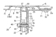
図4に概略的に示した自動車の運転席用の座席装置10は、座部11と、背もたれ部12とを備えている。座部11は、浅い皿状に成形された板金製のパンフレーム15と、パンフレーム15の上面側に設けられたパッド16などを備えて構成されている。パッド16の外側は図示しないカバー材によって覆われる。パッド16の材質は問わないが、例えばウレタンフォームのような合成樹脂の発泡体が適している。図5に示すように、フレーム15の底部15aとパッド16の下面との間に隙間17が確保されている。
【0014】
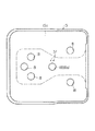
図6に示すように、パンフレーム15は板金をプレス等によって所定形状に成形したものであり、底部15aの適宜箇所に板厚方向に貫通する空気抜き用の孔18が打抜かれている。これらの孔18は、着座時にフレーム15とパッド16との間の隙間17の空気を逃がすためのものであり、異音の発生を防止する上で有効であるが、これらの孔18は、フレーム15を軽量化する上でも役立っている。
【0015】
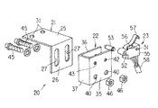
フレーム15の下面側には、着座者の荷重中心となるヒップポイントP(図4に示す)よりもやや前方の位置に、離着席検出用のスイッチユニット20が設けられている。図2等に示すようにスイッチユニット20は、ブラケット21と、スイッチホルダ22と、マイクロスイッチ23などを備えて構成されている。
【0016】
上記ブラケット21は、パンフレーム15の上記孔18のうち、ヒップポイントPに近い位置にある中央部の孔18aの周縁部近傍に固定される。ブラケット21は金属板をL形に折曲したものであり、水平方向の基部25と、基部25の端から下方に延びる縦壁26からなる。縦壁26には上下方向に沿う一対の長孔27が形成されている。
【0017】
図1に示されるように上記ブラケット21は、ねじあるいはリベット等の固定用部品30によってパンフレーム15の下面に固定され、縦壁26を孔18aの下方に臨ませている。図示例の場合には、基部25に設けられた小孔31と、フレーム15に設けられた小孔32に固定用部品30を挿通することにより、基部25をフレーム15に固定している。なお、スポット溶接等によって基部25をパンフレーム15に固定するようにしてもよい。
【0018】
ブラケット21にスイッチホルダ22が固定される。図2等に示されるようにスイッチホルダ22は金属板を上面側から見てコ字状となるように折曲したものであり、互いに離間する左右一対の側板部35,36と、側板部35,36をつなぐ連結壁37を有している。従ってこのスイッチホルダ22は上下両端と一側面が開口し、上端側が開放端となっている。
【0019】
一方の側板部35の下部に、水平方向に貫通するボルト貫通孔40が形成されている。他方の側板部36の下部にも水平方向のボルト挿通孔41が形成されている。側板部35,36の上部に、水平方向に貫通する小孔42,43が形成されている。
【0020】
スイッチホルダ22は、固定手段の一例としてのボルト45とナット46によって、ブラケット21に固定される。上記ボルト45は、ブラケット21の長孔27とスイッチホルダ22のボルト挿通孔40,41に挿入され、ナット46が螺合される。このためナット46を弛めれば、スイッチホルダ22を上下方向に移動させることができる。なお、側板部35,36の間にスペーサ47を設けてもよい。
【0021】
上記側板部35,36の間に、マイクロスイッチ23が挟まれた状態で固定されるようになっている。図示例の場合、マイクロスイッチ23の両側面に水平方向に突出する凸部51が設けられている。この凸部51は、スイッチホルダ22の孔42に嵌合させられる。マイクロスイッチ23に設けられた水平方向の貫通孔52にピン53が挿入される。ピン53の両端部は、スイッチホルダ22の小孔43に嵌合させられ、スイッチホルダ22に対するマイクロスイッチ23の位置決めと固定をなす。
【0022】
マイクロスイッチ23の本体55の上部に、突子56と、板ばね状に成形された作動部57が設けられている。本体55の内部には図示しない固定接点と可動接点が設けられており、突子56が本体55側に押込まれた時に、周知のスナップ機構を介して可動接点が固定接点に接することによって、このスイッチ23が閉路するようになっている。
【0023】
作動部57の先端部はスイッチホルダ22の側板部35,36の間から上方に突出しており、フレーム15の孔18aの内側の空間領域においてパッド16の下面と対向している。マイクロスイッチ23のリード線58は、図示しないコネクタとワイヤハーネスを介して、車両に搭載されたマイクロコンピュータ等の制御装置(図示せず)に接続される。
【0024】
パッド16の下面の一部、すなわちフレーム15の孔18aと対応した位置に含浸硬化層60が設けられている。含浸硬化層60は、パッド16のウレタンフォーム成形時に、成形用金型の内部の所定位置にフェルト材60aをインサートしておくことにより、ウレタンの発泡時にフェルト材60aにウレタンの一部を含浸させて一体に硬化させ、ウレタンのみの他の部位に比べて硬さを局部的に高めている。
【0025】
上記構成のスイッチユニット20をフレーム15に固定するには、予めマイクロスイッチ23をスイッチホルダ22に取付けておき、スイッチホルダ22とブラケット21をボルト45とナット46によって結合する。その場合に、ボルト45とナット46を弛めておき、仮止め状態にしておけば、ブラケット21に対してスイッチホルダ22を上下方向(図1中の矢印A方向)に移動させることができる。
【0026】
上記ブラケット21を固定用部品30によってフレーム15に固定したのち、パッド16の下面からパンフレーム15までの距離H(図1に示す)を治具によって測定し、距離Hに応じてスイッチホルダ22の高さを調整したのち、ボルト45とナット46を締付けることによってスイッチホルダ22をブラケット21に固定する。
【0027】
こうしてスイッチ23が規定高さにセッティングされるため、パッド16の上方から荷重が負荷されてパッド16が下がった時に、含浸硬化層60がスイッチ23の作動部57を確実に押すことができる。なお、長孔27を設ける代りに、縦壁26に複数の孔を段階的に高さを変えて設け、所望高さの孔にボルト45を通すようにしてもよい。
【0028】
次に上記構成のスイッチユニット20を備えた座席装置10の作用について説明する。
パッド16に荷重が負荷されていない時には、パッド16の下面とフレーム15との間に隙間17が存在している。その場合、含浸硬化層60とスイッチ23の作動部57との間が離れているため、スイッチ23は開路している。
【0029】
パッド16の上方から荷重が負荷されると、図3に示されるようにパッド16が下方に撓むことにより、含浸硬化層60がスイッチ23の作動部57に向って降下する。このため作動部57が押されてスイッチ23がオン状態に切換わる。そしてパッド16から荷重が除かれると、パッド16が元の高さに戻ることによってスイッチ23の作動部57からパッド16が離れるため、スイッチ23が再び開路する。こうして検出された離着席信号は、車載コンピュータ等の制御装置に入力され、離席あるいは着席に応じた各種制御動作がなされる。
【0030】
本実施例の座席装置10は、パッド16の一部(フレームの孔18aと対応した位置)に含浸硬化層60が設けられているため、パッド16に大きな荷重が加わっても、孔18aからパッド16が出過ぎることがない。しかも、含浸硬化層60にスイッチ23の作動部57が接触するため、着席時あるいは離席時における作動部57の応答性が良く、スイッチ23のオン・オフ動作が確実になされるものである。
【0031】
しかも作動部57がスイッチホルダ22の側板部35,36の間から上方に突出しており、側板部35,36の上方に含浸硬化層60が設けられているから、着座荷重が大きい時などに、図3中に2点鎖線Bで示すようにパッド16の下面が大きく下がっても、側板部35,36の上端によって含浸硬化層60が支持されることにより、作動部57が過剰に押されることを回避できる。
【0032】
【発明の効果】
本発明によれば、パンフレームとパッドを用いた座席装置において、パンフレームの下面側に設けたスイッチによって離着席信号を確実に取出すことができ、スイッチ等に不具合が生じた時にはスイッチの交換やメンテナンスを容易に行うことができる。また、パッドの上方から加わる荷重によってパッドの下面が下方に変位した時に、パッドの下面をスイッチホルダの側板部の上端によって支持でき、スイッチの作動部が押され過ぎることを回避できるため、着座荷重が大きくてもスイッチに過剰な負荷がかからず、耐久性が向上する。しかもブラケットに上下方向の長孔を設け、この長孔に沿ってスイッチホルダの高さを調整可能としているため、無負荷時におけるパンフレームからパッド下面までの距離に応じてスイッチの取付高さを調整でき、スイッチが確実に作動できるような高さにセッティングすることができる。このためスイッチの作動ストローク等に応じた位置にスイッチを保持でき、スイッチのオン・オフ動作を確実に行わせることができる。
【図面の簡単な説明】
【図1】本発明の一実施例を示す座席装置の一部の断面図。
【図2】図1に示された座席装置に使われるスイッチユニットの分解斜視図。
【図3】図1に示された座席装置に荷重が負荷された時の断面図。
【図4】図1に示された座席装置の全体の側面図。
【図5】図1に示された座席装置の一部の縦断側面図
【図6】図1に示された座席装置に使われるパンフレームの平面図。
【符号の説明】
10…座席装置 11…座部
15…フレーム 15a…底部
16…パッド 17…隙間
18a…孔 20…スイッチユニット
21…ブラケット 22…スイッチホルダ
23…スイッチ 27…長孔
35,36…側板部 45…ボルト(固定手段)
57…作動部 60…含浸硬化層[0001]
[Industrial application fields]
The present invention relates to a seat device having a seating detection function suitable for a vehicle seat such as an automobile.
[0002]
[Prior art]
As a means for electrically detecting the seating and leaving of an occupant in an automobile seat, for example, an automobile seat using a tape switch as described in Japanese Utility Model Publication No. 4-34109 has been proposed. . In this known technique, an elongated leaf spring that is curved along the back surface of the pad material is provided between the seat frame and the pad spring so that the center part floats from the seat frame. A tape switch is provided.
[0003]
This known technique is configured such that the leaf spring is largely bent downward by a load at the time of sitting, and the switch is turned on (energized state) when the tape switch is sandwiched between the seat frame and the leaf spring. ing. In the tape switch, at least a pair of contact portions that are vertically opposed to each other are embedded inside the belt-like elastic body, and when the pressure is applied in the thickness direction of the belt-like elastic body, the contact portion is closed and a closed circuit is formed. It is supposed to be formed.
[0004]
[Problems to be solved by the invention]
In the seat device using the tape switch, the operation reliability and durability of the switch are greatly affected by the seating load, the spring constant of the leaf spring, and the like. That is, if the spring constant of the leaf spring is lowered in order to increase the sensitivity of the switch, an excessive load continues to enter the tape switch for a large seating load, causing the tape switch to be plastically deformed or the contact portion to be worn. For example, malfunction may occur at an early stage.
[0005]
On the other hand, if the spring constant of the leaf spring is increased so as to withstand a large load, the sensitivity of the tape switch deteriorates and does not respond to a small seating load. Moreover, in the above prior art, when a trouble occurs in the tape switch or the leaf spring, the tape switch or the leaf spring is arranged inside the frame, so when a dish-like frame such as a pan frame is used, Tape switches and leaf springs cannot be easily replaced.
[0006]
In addition, instead of using a tape switch, in a seat device in which a load supporting spring is provided on the lower surface side of the pad, a micro switch having a lever that interlocks with the bending of the spring is provided so that the spring is constant when a load is applied. There has also been proposed a seat-seating detection means for detecting that the switch is bent more than the amount by the switch. However, this cannot be applied to a seat device in which a load is directly supported by a pan frame and a pad.
[0007]
Accordingly, an object of the present invention is to make it possible to reliably take out a seating / seating seat signal in a seat device provided with a pad on a pan frame, to be excellent in durability, and to easily exchange a switch or the like. is there.
[0008]
[Means for Solving the Problems]
The seat device of the present invention, which has been developed to achieve the above object, is a pan frame for a seat part that is formed in a dish shape and has a hole that penetrates in the vertical direction in the bottom part, and on the upper surface side of the pan frame. A pad that is provided and has a gap between the bottom of the pan frame, a bracket that is fixed in the vicinity of the hole in the bottom of the pan frame, a side plate that is open at the upper end side, and A switch holder provided on the lower surface side so as to be movable in the vertical direction with respect to the bracket, a fixing means for fixing the switch holder to a desired height with respect to the bracket, and an inner side of the hole of the frame fixed to the switch holder And a switch having an operating portion that protrudes upward from between the side plate portions and faces the lower surface of the pad.
[0009]
[Action]
When a load is applied from above the pad, the pad bends downward, so that the lower surface of the pad descends toward the operating portion of the switch. For this reason, an operation part is pushed by the lower surface of a pad, and a switch operates. When the load is removed, the pad returns to its original height, and the lower surface of the pad moves away from the operating portion of the switch, whereby the switch returns to its original state. The seating / separating seat signal detected by this switch is input to a control device such as a microcomputer provided in the vehicle, and various control operations are performed according to the seating or seating.
[0010]
Since the switch operating part protrudes upward from the side plate of the switch holder and faces the lower surface of the pad, the lower surface of the pad does not move even if the pad position drops more than expected when a large seating load is applied. It is supported by the peripheral edge of the hole in the frame and the upper end of the side plate. For this reason, even if the seating load is large, the switch is prevented from being pushed with an excessive force, and the durability of the switch is not adversely affected.
[0011]
In the present invention, the bracket is provided with an elongated hole in the vertical direction, and the height of the switch holder can be adjusted along the elongated hole, so that the switch can be switched according to the distance from the pan frame to the lower surface of the pad when there is no load. The mounting height can be adjusted, and the height can be set so that the switch can operate reliably.
[0012]
Further, when the impregnated hardened layer is provided on a part of the pad (position corresponding to the hole of the pan frame ) as in the second aspect , an appropriate hardness can be given to the portion in contact with the switch operating portion. Further, by providing such an impregnated hardened layer, the bottom surface of the pad does not protrude from the hole of the pan frame to the lower surface side, and the portion is easily received by the upper end surface of the side plate portion of the switch holder.
[0013]
【Example】
An embodiment of the present invention will be described below with reference to the drawings.
A
[0014]
As shown in FIG. 6, the
[0015]
On the lower surface side of the
[0016]
The
[0017]
As shown in FIG. 1, the
[0018]
A
[0019]
A bolt through
[0020]
The
[0021]
The
[0022]
At the upper part of the
[0023]
The distal end portion of the operating
[0024]
An impregnated
[0025]
In order to fix the
[0026]
After the
[0027]
Since the
[0028]
Next, the operation of the
When no load is applied to the
[0029]
When a load is applied from above the
[0030]
In the
[0031]
Moreover, since the operating
[0032]
【The invention's effect】
According to the present invention, in a seat device using a pan frame and a pad, a take-off / seating signal can be surely taken out by a switch provided on the lower surface side of the pan frame, and when a trouble occurs in the switch or the like, Maintenance can be performed easily. In addition, when the lower surface of the pad is displaced downward by a load applied from above the pad, the lower surface of the pad can be supported by the upper end of the side plate portion of the switch holder, and it is possible to prevent the switch operating portion from being pushed too much. Even if is large, an excessive load is not applied to the switch, and durability is improved. In addition, the bracket has a long hole in the vertical direction, and the height of the switch holder can be adjusted along this long hole, so the switch mounting height can be adjusted according to the distance from the pan frame to the bottom of the pad when there is no load. It can be adjusted and set to a height that ensures the switch can be operated. For this reason, the switch can be held at a position corresponding to the operation stroke of the switch, and the on / off operation of the switch can be surely performed.
[Brief description of the drawings]
FIG. 1 is a partial cross-sectional view of a seat device showing an embodiment of the present invention.
FIG. 2 is an exploded perspective view of a switch unit used in the seat device shown in FIG.
FIG. 3 is a cross-sectional view when a load is applied to the seat device shown in FIG. 1;
4 is a side view of the entire seat device shown in FIG. 1. FIG.
FIG. 5 is a vertical side view of a part of the seat apparatus shown in FIG. 1. FIG. 6 is a plan view of a pan frame used in the seat apparatus shown in FIG.
[Explanation of symbols]
DESCRIPTION OF
57 ...
Claims (2)
上記パンフレームの上面側に設けられかつこのパンフレームの底部との間に隙間を有するパッドと、
上記パンフレームの底部の上記孔の近傍に固定されるブラケットと、
上端側が開放された側板部を有しかつ上記パンフレームの下面側において上記ブラケットに対し上下方向に移動可能に設けられたスイッチホルダと、
上記スイッチホルダを上記ブラケットに対し所望高さに固定する固定手段と、
上記スイッチホルダに固定されかつ上記パンフレームの孔の内側の空間に臨んで上記側板部の間から上方に突出して上記パッドの下面と対向する作動部を有するスイッチとを具備し、
上記ブラケットは上記パンフレームに固定される基部と、この基部から下方に延びる縦壁とを有しており、この縦壁に上下方向に沿う長孔が設けられており、この長孔に上記スイッチホルダを固定するためのボルトを水平方向に挿通し、かつ上記スイッチホルダを上記ブラケットに対して所望高さに位置させたところで上記ボルトによって上記スイッチホルダをブラケットに固定するようにしたことを特徴とする座席装置。A pan frame for a seat part formed in a dish shape and provided with a hole penetrating vertically in the bottom part;
A pad provided on the upper surface side of the pan frame and having a gap with the bottom of the pan frame;
A bracket fixed near the hole at the bottom of the pan frame;
A switch holder provided with a side plate portion whose upper end side is open and movably in the vertical direction with respect to the bracket on the lower surface side of the pan frame;
Fixing means for fixing the switch holder to the bracket at a desired height;
A switch fixed to the switch holder and facing the space inside the hole of the pan frame and having an operating portion that protrudes upward from between the side plate portions and faces the lower surface of the pad ;
The bracket has a base fixed to the pan frame and a vertical wall extending downward from the base, and a long hole extending in the vertical direction is provided in the vertical wall, and the switch is provided in the long hole. A bolt for fixing the holder is inserted in a horizontal direction, and the switch holder is fixed to the bracket by the bolt when the switch holder is positioned at a desired height with respect to the bracket. Seat equipment to play.
Priority Applications (1)
| Application Number | Priority Date | Filing Date | Title |
|---|---|---|---|
| JP19537594A JP3639617B2 (en) | 1994-08-19 | 1994-08-19 | Seat device |
Applications Claiming Priority (1)
| Application Number | Priority Date | Filing Date | Title |
|---|---|---|---|
| JP19537594A JP3639617B2 (en) | 1994-08-19 | 1994-08-19 | Seat device |
Publications (2)
| Publication Number | Publication Date |
|---|---|
| JPH0864056A JPH0864056A (en) | 1996-03-08 |
| JP3639617B2 true JP3639617B2 (en) | 2005-04-20 |
Family
ID=16340127
Family Applications (1)
| Application Number | Title | Priority Date | Filing Date |
|---|---|---|---|
| JP19537594A Expired - Fee Related JP3639617B2 (en) | 1994-08-19 | 1994-08-19 | Seat device |
Country Status (1)
| Country | Link |
|---|---|
| JP (1) | JP3639617B2 (en) |
Families Citing this family (1)
| Publication number | Priority date | Publication date | Assignee | Title |
|---|---|---|---|---|
| LU92671B1 (en) | 2015-02-27 | 2016-08-29 | Iee Int Electronics & Eng Sa | Weight-responsive vehicle seat occupant detection and classification method and system |
-
1994
- 1994-08-19 JP JP19537594A patent/JP3639617B2/en not_active Expired - Fee Related
Also Published As
| Publication number | Publication date |
|---|---|
| JPH0864056A (en) | 1996-03-08 |
Similar Documents
| Publication | Publication Date | Title |
|---|---|---|
| US9533603B2 (en) | Seat occupancy sensor unit at a lower B-surface side of a seat cushion | |
| US5085462A (en) | Airbag and vehicle horn switch assembly | |
| US5597067A (en) | Pushbutton switch | |
| US9776530B2 (en) | Vehicle seat suspension mat | |
| US4678058A (en) | Vehicle seat switch | |
| JP2014084069A (en) | Occupant detection device | |
| JP2001070091A (en) | Mounting structure of vehicle occupant detection sensor | |
| US6546822B1 (en) | Seat occupant sensor device | |
| US4436970A (en) | Switch assemblies | |
| CN100417542C (en) | Seat unit with operator presence switch | |
| JP3639617B2 (en) | Seat device | |
| US6327917B1 (en) | Device for detecting a pressure exerted upon the seat of a motor vehicle | |
| US20030177847A1 (en) | Load detection structure in a sliding seat | |
| JP2000037256A (en) | Mounting structure of seat switch on seat | |
| JP3812905B2 (en) | Occupant detection device | |
| CN110920491A (en) | Foam structure for automobile seat and automobile seat | |
| US6640653B1 (en) | Load detection structure for vehicle seat | |
| JP7401807B2 (en) | Sensor arrangement structure on the seat | |
| JP4072042B2 (en) | Interlock device for vehicle seat | |
| JPH11507759A (en) | Power seat position adjustment device | |
| EP3381740B1 (en) | Seating sensor | |
| KR20190001267A (en) | Device for operating horn of vehicle | |
| US20250256629A1 (en) | Seat cushion | |
| CN208291163U (en) | The component that air bag device and steering wheel are formed | |
| JP7060817B2 (en) | Vehicle seat |
Legal Events
| Date | Code | Title | Description |
|---|---|---|---|
| A977 | Report on retrieval |
Free format text: JAPANESE INTERMEDIATE CODE: A971007 Effective date: 20040611 |
|
| A131 | Notification of reasons for refusal |
Free format text: JAPANESE INTERMEDIATE CODE: A131 Effective date: 20040706 |
|
| A521 | Request for written amendment filed |
Free format text: JAPANESE INTERMEDIATE CODE: A523 Effective date: 20040906 |
|
| TRDD | Decision of grant or rejection written | ||
| A01 | Written decision to grant a patent or to grant a registration (utility model) |
Free format text: JAPANESE INTERMEDIATE CODE: A01 Effective date: 20050111 |
|
| A61 | First payment of annual fees (during grant procedure) |
Free format text: JAPANESE INTERMEDIATE CODE: A61 Effective date: 20050117 |
|
| R150 | Certificate of patent or registration of utility model |
Free format text: JAPANESE INTERMEDIATE CODE: R150 |
|
| FPAY | Renewal fee payment (event date is renewal date of database) |
Free format text: PAYMENT UNTIL: 20090121 Year of fee payment: 4 |
|
| LAPS | Cancellation because of no payment of annual fees |