JP3642995B2 - Processing apparatus, processing method, and method for producing detoxified object to be processed - Google Patents
Processing apparatus, processing method, and method for producing detoxified object to be processed Download PDFInfo
- Publication number
- JP3642995B2 JP3642995B2 JP32599899A JP32599899A JP3642995B2 JP 3642995 B2 JP3642995 B2 JP 3642995B2 JP 32599899 A JP32599899 A JP 32599899A JP 32599899 A JP32599899 A JP 32599899A JP 3642995 B2 JP3642995 B2 JP 3642995B2
- Authority
- JP
- Japan
- Prior art keywords
- treated
- gas
- treatment
- heat
- alkali
- Prior art date
- Legal status (The legal status is an assumption and is not a legal conclusion. Google has not performed a legal analysis and makes no representation as to the accuracy of the status listed.)
- Expired - Fee Related
Links
Images


Classifications
-
- Y—GENERAL TAGGING OF NEW TECHNOLOGICAL DEVELOPMENTS; GENERAL TAGGING OF CROSS-SECTIONAL TECHNOLOGIES SPANNING OVER SEVERAL SECTIONS OF THE IPC; TECHNICAL SUBJECTS COVERED BY FORMER USPC CROSS-REFERENCE ART COLLECTIONS [XRACs] AND DIGESTS
- Y02—TECHNOLOGIES OR APPLICATIONS FOR MITIGATION OR ADAPTATION AGAINST CLIMATE CHANGE
- Y02E—REDUCTION OF GREENHOUSE GAS [GHG] EMISSIONS, RELATED TO ENERGY GENERATION, TRANSMISSION OR DISTRIBUTION
- Y02E50/00—Technologies for the production of fuel of non-fossil origin
- Y02E50/30—Fuel from waste, e.g. synthetic alcohol or diesel
Landscapes
- Processing Of Solid Wastes (AREA)
Description
【0001】
【発明の属する技術分野】
本発明は、例えば焼却灰等を無害化して再利用を図ることができる処理装置、処理方法及び無害化した処理対象物体の生産方法に関する。
【0002】
【従来の技術】
近年、ダイオキシン、PCB、コプラナPCB等の有機ハロゲン化物やPb等の重金属の環境への拡散とその影響が大きな社会問題となっている。例えば廃棄物を燃焼処理、熱分解処理した残渣や焼却灰、土壌、汚泥等には、ダイオキシン、PCB、コプラナPCB等の有害な有機ハロゲン化物やPb等の重金属が残留している。
【0003】
例えば有機ハロゲン化物を含む有害物質を除去する方法としては、有機ハロゲン化物を含有する加熱残渣を高温加熱したり、約1500°C前後の高温で溶融処理することにより有機ハロゲン化物濃度を低減する手法が提案されている。
【0004】
【発明が解決しようとする課題】
しかしながら、このような方法では、Pb等の重金属については十分に除去できない、という問題がある。
【0005】
また、本発明者等の考察によれば、上記のように処理された後の焼却灰にはアルカリ成分が含有されていることから、たとえ有機ハロゲン化物を発生させずに重金属を除去してもそのような焼却灰を再利用するには問題があることが判明した。例えば、アルカリ成分の多い焼却灰をセメントや煉瓦に再利用した場合にこれらセメントや煉瓦がアルカリ反応を起こして膨張し、破壊することがある。
【0006】
本発明の主たる目的は、有機ハロゲン化物が発生することもなく、重金属を含有する処理対象物体を無害化し、更には処理後の処理対象物体を有効に再利用することがきる処理装置、処理方法及び無害化した処理対象物体の生産方法を提供することにある。
【0007】
【課題を解決するための手段】
かかる課題を解決するため、本発明の処理装置は、処理対象物体を加熱処理する加熱手段と、前記加熱処理された処理対象物体を塩素成分の除去された空気を使って酸化させ、冷却処理する手段と、前記冷却処理された処理対象物体からアルカリ成分を抽出する抽出手段とを具備することを特徴とする。又は、本発明は、処理対象物体からアルカリ成分を抽出する抽出手段と、前記アルカリ成分の抽出された処理対象物体を加熱処理する加熱手段と、前記加熱処理された処理対象物体を塩素成分の除去された空気を使って酸化させ、冷却処理する手段とを具備することを特徴とする。
ここで、処理対象物体には、例えば焼却灰、土壌、汚泥等がある。
【0008】
本発明では、加熱処理された処理対象物体を空気を使って酸化させているので、重金属が酸化されて無害化される。また、その空気は塩素成分が除去されているので、該空気を使って処理対象物体を冷却処理する際に処理対象物体に含有するカーボン等と反応して、有機ハロゲン化物が発生することは少ない。更に、上記冷却処理された処理対象物体からアルカリ成分を抽出しているので、処理対象物体及びアルカリ抽出液を有効に再利用することができる。
【0009】
本発明の処理装置では、前記加熱手段は、前記処理対象物体を減圧下で加熱処理することを特徴とする。処理対象物体を減圧下で加熱処理することにより処理対象物体からアルカリ成分及び重金属を抽出することができる。また、処理対象物体を常圧付近で加熱溶融することも考えられるが、融点が高いことから、高価で大規模な設備が必要となり、ランニングコストも高い等の問題がある。これにに対して、処理対象物体を減圧下で加熱処理することで沸点が下がり有害金属、有害ガスを除去できるので、上記問題が解消する。
【0010】
本発明の処理装置は、第1の処理対象物体を熱分解する熱分解手段と、前記熱分解の際に発生する分解ガスを抽出する分解ガス抽出手段と、前記熱分解された第1の処理対象物体(例えばカーボンを含んでいる)及び第2の処理対象物体を加熱処理する加熱手段と、前記加熱処理された第1及び第2の処理対象物体を塩素成分の除去された空気を使って酸化させ、冷却処理する手段と、前記冷却処理された第1及び第2の処理対象物体からアルカリ成分を抽出するアルカリ成分抽出手段と、前記抽出されたアルカリ成分により前記分解ガス抽出手段で抽出された分解ガスを中和する中和手段ととを具備することを特徴とする。なお、加熱残渣中に空気による冷却後も有害重金属を残留する危険性がある場合には減圧処理後直ちに酸化処理を行った後に冷却処理するようにしてもよい。
【0011】
ここで、第1の処理対象物体には、カーシュレッダーダスト、廃家電、廃プラスチック、廃材、紙、油等がある。また、第2の処理対象物体には、例えば焼却灰、土壌、汚泥等がある。
【0012】
本発明では、上記と同様に、加熱処理された第1及び第2の処理対象物体中の重金属等を例えば真空蒸発回収後に更に空気を使って酸化させているので、重金属が酸化されて無害化される。また、その空気は塩素成分が除去されているので、該空気を使って第1及び第2の処理対象物体を冷却処理する際に処理対象物体に含有するカーボンと反応し、有機ハロゲン化物が発生することはない。更に、上記冷却処理された第1及び第2の処理対象物体からアルカリ成分を抽出しているので、第1及び第2の処理対象物体を有効に再利用することができる。これに加えて本発明によれば、アルカリ成分抽出手段により抽出されたアルカリ成分により分解ガス抽出手段で抽出された分解ガスを中和しているので、分解ガスをクリーンガスとして有効に再利用することができる。また、このアルカリ抽出液で処理対象物体のアルカリ溶解金属等を溶解除去できる。
【0013】
本発明の処理装置では、前記熱分解手段は、爆発限界以下の減圧下で前記第1の処理対象物体を熱分解する。これにより、効率よく且つ安全に第1の処理対象物体を熱分解することができる。
【0014】
本発明の処理装置では、前記加熱手段は、前記第1及び第2の処理対象物体を減圧下で加熱処理することを特徴とする。これにより、残渣や廃ガス中にダイオキシン、コプラナP.C.B等に含有することはなく、上記と同様に、第1及び第2の処理対象物体からアルカリ成分を抽出することができ、このアルカリ成分を使用し、またアルカリ蒸発物により本装置で発生する有毒酸化ガス等を中和することができ、更に安価で小規模な設備でよく、ランニングコストも低減する。
【0015】
本発明の処理装置では、前記加熱手段は、前記分解ガス抽出手段により抽出されて前記中和手段により中和された分解ガスを用いて加熱処理することを特徴とする。これにより、エネルギーを有効に再利用することができる。
【0016】
本発明の処理装置では、前記熱分解手段は、前記分解ガス抽出手段により抽出されて前記中和手段により中和された分解ガスを用いて加熱処理することを特徴とする。これにより、エネルギーを有効に再利用することができる
【0017】
本発明の処理装置は、処理対象物体に対して加熱処理を行う処理炉と、前記減圧加熱処理された後に前記処理炉内に塩素成分の除去された空気を供給する手段とを具備することを特徴とする。
【0018】
本発明では、加熱処理された後の処理対象物体に塩素成分の除去された空気を供給しているので、例えば燃焼により重金属が酸化されて無害化され、該空気による冷却の際に有機ハロゲン化物が発生することはな少ない。また、冷却に酸化処理が必要ない場合にはN2ガス等の不活性ガスでもよい。
【0019】
本発明の処理装置は、処理対象物体に対して加熱処理を行う手段と、前記加熱処理された処理対象物体からアルカリ成分を除去する手段とを具備することを特徴とする。
【0020】
本発明では、上記冷却処理された処理対象物体からアルカリ成分を抽出しているので、処理対象物体(金属溶解とガスの中和等)を有効に再利用することができる。
【0021】
本発明の加熱処理装置は、処理対象物体に対して減圧下で加熱処理を行う手段と、前記加熱処理の際に、前記処理対象物体から蒸発するアルカリ成分と有機ハロゲン化物や他のガスとを中和させ、その生成物を回収する手段とを具備することを特徴とする。
【0022】
本発明の処理方法は、処理対象物体を加熱処理する工程と、前記加熱処理された処理対象物体を塩素成分の除去された空気(純酸素や純酸素に近い状態も含む)で酸化する工程と、前記酸化された処理対象物体を冷却処理する工程と、前記冷却処理された処理対象物体からアルカリ成分を抽出する工程とを具備することを特徴とする。
【0023】
本発明の処理方法は、第1の処理対象物体を熱分解する工程と、前記熱分解の際に発生する分解ガスを抽出する工程と、前記熱分解された第1の処理対象物体及び第2の処理対象物体を加熱処理する工程と、前記加熱処理された第1及び第2の処理対象物体を塩素成分の除去された空気で酸化する工程と、前記酸化された第1及び第2の処理対象物体を冷却処理する工程と、前記冷却処理された第1及び第2の処理対象物体からアルカリ成分を抽出する工程と、前記抽出されたアルカリ成分により前記抽出された分解ガスを中和する工程とを具備することを特徴とする。
【0024】
本発明の処理方法は、処理対象物体を加熱処理する工程と、前記加熱処理された処理対象物体を塩素成分の除去された空気で酸化する工程と、前記酸化された処理対象物体を冷却処理する工程とを具備することを特徴とする。
【0025】
本発明の処理方法は、処理対象物体を加熱処理する工程と、前記加熱処理された処理対象物体からアルカリ成分を抽出する工程とを具備することを特徴とする。
【0026】
本発明は、無害化した処理対象物体を生産する方法において、処理対象物体を加熱処理する工程と、前記加熱処理された処理対象物体を塩素成分の除去された空気で酸化する工程と、前記酸化された処理対象物体を冷却処理する工程と、前記冷却処理された処理対象物体からアルカリ成分を抽出する工程とを具備することを特徴とする。
【0027】
本発明は、無害化した処理対象物体を生産する方法において、第1の処理対象物体を熱分解する工程と、前記熱分解の際に発生する分解ガスを抽出する工程と、前記熱分解された第1の処理対象物体及び第2の処理対象物体を加熱処理する工程と、前記加熱処理された第1及び第2の処理対象物体を塩素成分の除去された空気で酸化する工程と、前記酸化された第1及び第2の処理対象物体を冷却処理する工程と、前記冷却処理された第1及び第2の処理対象物体からアルカリ成分を抽出する工程と、前記抽出されたアルカリ成分により前記抽出された分解ガスを中和する工程とを具備することを特徴とする。
【0028】
本発明は、無害化した処理対象物体を生産する方法において、処理対象物体を加熱処理する工程と、前記加熱処理された処理対象物体を塩素成分の除去された空気で酸化する工程と、前記酸化された処理対象物体を冷却処理する工程とを具備することを特徴とする。但し、真空蒸発処理のみで無害化できる場合は酸化処理、酸化冷却は不要となる。
【0029】
本発明は、無害化した処理対象物体を生産する方法において、処理対象物体を加熱処理する工程と、前記加熱処理された処理対象物体からアルカリ成分を抽出する工程とを具備することを特徴とする。
【0030】
本発明は、処理対象物体に対して減圧下で加熱処理を行う手段と、前記加熱処理の際に、前記処理対象物体から蒸発するアルカリ成分と有機ハロゲン化物、NOx、SOx等の酸性ガスとを中和させ、その生成物を回収する手段とを具備することを特徴とする。
【0031】
以上の方法発明についても上記装置発明と同様の作用効果を奏するものである。
【0032】
【発明の実施の形態】
以下、本発明の実施の形態を図面に基づき説明する。
この実施形態は、本発明をシュレッダーダストのエネルギーを利用して焼却灰を無害化する処理システムに適用したものである。
【0033】
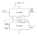
図1はこの処理システムの概略構成を示す図である。
この処理システム11は、シュレッダーダストを熱分解する第1の処理系12と、前記熱分解されたシュレッダーダストの焼却灰及び焼却灰を加熱処理する第2の処理系13とを備える。
【0034】
第1の処理系12では、シュレッダーダストを熱分解するときに発生する分解ガスを用いて発電が行われ、その電力、分解ガス(クリーンガス)及び加熱残渣のカーボンの燃焼ガスが第2の処理系13で焼却灰を加熱処理するときのエネルギーとして又分解ガスのエネルギーとしても利用されるようになっている。第1の処理系12により熱分解されたシュレッダーダストからは、金属、ガラス、酸化物等が回収される。
【0035】
第2の処理系13では、加熱処理後の焼却灰からアルカリ成分が抽出され、そのアルカリ水溶液が第1の処理系12に供給され、上記の第1の処理系12における発生した分解ガス中のハロゲン化物、NOx、SOx等の酸化物質を中和する中和液として利用されるようになっている。また、アルカリ性溶解金属はこのときアルカリ成分と同時に溶解して除去される。
【0036】
第1の処理系12で熱分解されたシュレッダーダストの焼却灰は、第2の処理系13で、直接投入された焼却灰とともに加熱処理されるようになっている。そして、第2の処理系13により加熱処理されてアルカリ成分が抽出された焼却灰は無公害無機物としてセメントや煉瓦等の建築資材、田畑、土木資材等に再利用されるようになっている。なお、アルカリ成分の必要とする焼却灰はアルカリ抽出しない場合もある。
【0037】
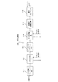
図2は上述した第1の処理系12の構成を示す図である。
受け入れ設備21は、外部からシュレッダーダストを受け入れ、受け入れたシュレッダーダストを後段の減圧熱分解炉22へ移送する、例えばベルトコンベアにより構成される。
【0038】
減圧熱分解炉22は、受け入れ設備21から移送されたシュレッダーダストを減圧下で加熱処理する。これにより、シュレッダーダストは熱分解され、分解ガスが発生すると共に、金属、ガラス、酸化物、焼却灰等からなる分解残渣とされる。発生した分解ガスはガス処理系24により回収され、分解残渣は分別機23に搬送される。
【0039】
ガス処理系24では、分解ガスが第2の処理系13側から供給される中和液としてのアルカリ水溶液により中和等されて蓄積されるようになっている。この蓄積された分解ガスはガスエンジン25に供給されて発電機26の発電用のエネルギーとして用いられるようになっている。また、この蓄積されたガスは減圧熱分解炉22及び第2の処理系13の真空炉(後述する)、熱風炉27に供給され、炉を外側から加熱するためのエネルギーとして用いられるようになっている。
【0040】
ガスエンジン25は発電機26を駆動するために用いられる。発電機26で発電された電力は第2の処理系13の真空炉(後述する)のエネルギーとして用いられる。また、発電機26で発電された電力は第1の処理系2内で用いることもできるし、システム外で用いることも可能である。
【0041】
分別機23は、例えば強力な電磁石を用いて金属を分別回収し、更に送風機を用いて分解残渣(カーボン)を分別回収する。分別回収された金属やガラス、酸化物は例えばベルトコンベアを介してシステム外に回収される。また、分別回収されたカーボンは熱風炉27に搬送される。
【0042】
熱風炉27は、搬入されたカーボンを燃料として例えば500〜800℃の範囲の温度の熱風を作り、この熱風を各部に加熱エネルギーとして供給する。これにより省エネルギー化を図ることができる。
【0043】
熱風炉27には、熱風用の空気として例えば設備付近の空気を、活性炭等を用いて空気から塩素成分等を除去するフィルタ28を介して供給される。熱風炉27から排出された熱風はガス処理系24及び第2の処理系13の真空炉(後述する)における加熱用のガスとして用いられるようになっている。
【0044】
上述したフィルタ28を介して塩素成分が除去された空気は減圧熱分解炉22にも供給されて燃焼用及び冷却用の空気として用いられる。このように、空気から塩素成分を除去して用いることで、ダイオキシン等の有機ハロゲン化物の発生を抑制することができる。
【0045】
熱風炉27で熱風にて生成された焼却灰は第2の処理系13に搬送される。
図3は上述した第2の処理系13の構成を示す図である。
受け入れ設備31は、外部から焼却灰を受け入れ、受け入れた焼却灰を後段の灰サイロ32へ移送する、例えばベルトコンベアにより構成される。灰サイロ32では、受け入れ設備31及び第1の処理系12から移送された焼却灰を蓄積する。
【0046】
真空炉33は、灰サイロ32から焼却灰を供給され、供給された焼却灰を減圧下で加熱処理することにより有害重金属及びアルカリ成分を回収する。また、この真空炉33には、燃焼及び冷却用の空気として例えば設備付近の空気を、活性炭等を用いて空気から塩素成分等を除去するフィルタ34を介して供給される。そして、この真空炉33では、加熱処理された後の焼却灰を上記の塩素成分の除去された空気で燃焼し、その後冷却する。
【0047】
アルカリ成分抽出部35は、真空炉33で加熱処理された焼却灰からアルカリ成分を抽出する。そして、アルカリ成分が抽出された焼却灰はシステム外に搬出され、上述したように再利用される。アルカリ成分抽出部35では、中性の水が供給され、この水を用いて焼却灰からアルカリ成分を抽出している。アルカリ成分を抽出してアルカリ化してアルカリ水溶液はアルカリ性水処理装置37に送水される。また、アルカリ成分抽出部35及びアルカリ性水処理装置37から溢れたアルカリ水溶液は浸透膜やイオン交換樹脂等のイオン交換体を有するフィイル38を介してアルカリ成分が回収されるようになっている。なお、アルカリ成分抽出部35に供給される中性の水は、真空炉33における冷却用の水として使われた後にアルカリ成分抽出部35に供給されるようになっている。これにより、後述するようにアルカリ成分抽出部35に供給される水を高温にして供給する必要がある場合があるが、そのような場合にエネルギーを有効利用することによりアルカリ抽出の効率を高めることができる。
【0048】
アルカリ性水処理装置37では、送水されたアルカリ水溶液を蓄積すると共に、必要に応じて苛性ソーダ(水酸化ナトリウム)や消石等が供給され、アルカリ水溶液のアルカリ性が維持されるようになっている。また、アルカリ性水処理装置37からガス洗浄装置39及び第1の処理系12のガス処理系24のガス洗浄装置(後述する)、その他のガス処理装置にアルカリ水溶液が送水されるようになっている。
【0049】
ガス洗浄装置39は、真空炉33から排出される排気ガスをアルカリ性水処理装置37から供給されるアルカリ水溶液で例えばシャワーリングする。これにより、真空炉33から排出されるNOx、SOx、ダイオキシン等の有機ハロゲン化物及び分解物を含んだ排気ガスがアルカリ水溶液によって中和されて無害化される。
【0050】
図4は上述した減圧熱分解炉22の構成を示す図である。
減圧熱分解炉22は、パージ室41、気密室42、冷却室43から構成されている。
【0051】
これら各室は開閉可能な隔壁である扉44によって隔てられている。すなわち、装置外部とパージ室41、パージ室41と気密室42、気密室42と冷却室43、冷却室43と装置外部とは扉44によりそれぞれ隔てられている。そして、減圧熱分解を行うシュレッダーダストは、外部からパージ室41、気密室42、冷却室43、外部の順番で例えば炉内の搬送装置により搬送されるようになっている。また、これら各室を隔てる扉44は気密保持性と断熱性とを備えており、各室を熱的、圧力的に隔てている。加熱室が高温の場合、気密扉と断熱扉の二重構造としてもよい。
【0052】
パージ室41及び冷却室43には排気系45が接続されている。また、気密室42で発生するシュレッダーダストを熱分解するときに発生する分解ガスはポンプ46を介して外部(ガス処理系24)に排出されるようによっている。シュレッダーダストを熱分解するときに発生する分解ガスには、クラッキン装置を介することで生じる、メタンガス、エタンガス、水素ガス、一酸化炭素等があるが、これらの分解ガスには一般的にNOx、SOx、ダイオキシン等の有機ハロゲン化物等の有害物質が含まれている。
【0053】
気密室42内はポンプ46による排気により1〜50torr、より好ましくは20torr(260パスカル)程度に減圧されるようになっている。このように爆発限界以内の圧力で処理することで安全性を高めることができる。
【0054】
気密室42はガスバーナー等の加熱手段47によって600〜1200℃、より好ましくは800℃で加熱されるようになっている。加熱手段47には燃焼用のエネルギーとしてガス処理系24からクリーンガスが供給されるようになっている。これによりエネルギーを有効利用することができる。
【0055】
冷却室43では、気密室42で減圧熱分解された分解残渣の冷却が行われる。この冷却室43には上述した例えば設備付近から供給される空気を、活性炭等を用いて空気から塩素成分を除去するフィルタ28を介して供給され、この空気が酸化剤、加熱用空気及び冷却用の媒体として用いられる。このように冷却用の媒体としての空気は塩素成分が除去されているので、有機ハロゲン化物が発生することはない。処理物の酸化処理が必要ない場合にはN2ガスでもよい。
【0056】
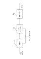
図5は上述したガス処理系24の構成を示す図である。
ガス高温クラッキング部51では、減圧熱分解炉22から送出される分解ガスを例えば1000℃程度にてクラッキングする。
【0057】
ガス急冷部52ではクラッキングされた分解ガスを例えば10秒以内に1000℃から100℃程度に急冷する。このように急冷することでダイオキシンなどの有機ハロゲン化物の発生を抑制することができる。この場合、抽出アルカリ水溶液で中和処理を同時にすることも合理的な方法である。
【0058】
アルカリ式バグフィルター53では、上記急冷された分解ガスを苛性ソーダや消石灰を通過させることで酸性化されている分解ガスを中和する。
【0059】
ガス洗浄装置54では、上記フィルター53を通解した分解ガスを第2の処理系13のアルカリ性水処理装置37から供給されるアルカリ水溶液で例えばシャワーリングする。これにより、NOx、SOx、ダイオキシン等の有機ハロゲン化物を含んだ分解ガスがアルカリ水溶液によって中和されて無害化される。また、アルカリ性水処理装置37から供給されるアルカリ水溶液を用いることで構成を簡単化でき、更に省資源化することにもなり、ランニングコストの低減を図ることができる。
【0060】
そして、分解ガスは触媒式脱硫装置55でSOx等が除去され高圧ガスタンク56に蓄積される。高圧ガスタンク56より、ガスエンジン25、減圧熱分解炉22、真空炉33に対してクリーンガスが燃焼用のエネルギーとして供給される。これにより、エネルギーを効率的に利用することができる。
【0061】
図6は上述した真空炉33の構成を示す図である。
真空炉33は、パージ室61、気密室62、冷却室63から構成されている。
これら各室は開閉可能な隔壁である扉64によって隔てられている。すなわち、装置外部とパージ室61、パージ室61と気密室62、気密室62と冷却室63、冷却室63と装置外部とは扉64によりそれぞれ隔てられている。そして、減圧加熱処理を行う焼却灰は、灰サイロ32からパージ室61、気密室62、冷却室63、アルカリ成分抽出部35の順番で例えば炉内の搬送装置により搬送されるようになっている。また、これら各室を隔てる扉64は気密保持性と断熱性とを備えており、各室を熱的、圧力的に隔てている。なお、気密扉と断熱扉を一対にしてもよい。
【0062】
パージ室61、気密室62及び冷却室63には排気系65が接続されている。排気系65からの排気は上述したガス洗浄装置39に送出される。
【0063】
気密室62内は上記の排気により1×10⁻¹〜50torr、より好ましくは7×10⁻¹torr程度に減圧されるようになっている。蒸発物及び反応物は真空ポンプと気密室との間に介挿された回収装置69により回収される。回収される迄にアルカリは酸性ガス等と反応して中和される。即ち、ダイオキシン、コプラナP.C.B、トリクロールエチレン等の熱分解により生じた酸性ガスがアルカリと反応し、回収装置69によりNaCl等の中性物質として回収され、排気ガスは無公害ガスとなる。
【0064】
気密室62はそれぞれガスバーナー等の加熱手段66、67によって800〜1200℃、より好ましくは1000℃で加熱されるようになっている。加熱手段66、67には燃焼用のエネルギーとしてガス処理系24からクリーンガスが供給されるようになっている。これによりエネルギーを有効利用することができる。
【0065】
冷却室63では、重金属が多く減圧加熱蒸発で除去できない場合には気密室62で減圧加熱処理された焼却灰をまず600〜900℃、より好ましくは800℃程度で燃焼(酸化)し、無公害残渣としてその後常温に冷却するようになっている。この冷却室43にはN2クリーン空気又は水を冷却媒体とする冷却手段68が隣接している。冷却手段68で使用され高温となった水は後段のアルカリ成分抽出部35に供給され、アルカリ成分の抽出用の媒体として用いられるようになっている。また、この冷却室43には上述した例えば設備付近から供給される空気が、活性炭等の吸着剤を用いて空気から塩素成分を除去するフィルタ34を介して供給され、この空気が燃焼用及び冷却用の媒体として用いられる。このように焼却灰を空気を使って燃焼させているので、重金属が酸化されて無害化される。また、その空気は塩素成分が除去されているので、該空気を使って焼却灰を冷却処理する際に焼却灰に含有するカーボンが燃焼し、有機ハロゲン化物が発生することはない。
【0066】
図7は上記したフィルタ28、34の構成を示す図である。
筒状のフィルター本体71の一端に例えば設備付近から供給される空気が供給される入力孔72が設けられ、他端には出力孔73が設けられている。そして、フィルター本体71内には吸着剤、例えば活性炭74が挿入され、入力孔72から入った空気が活性炭74を通過して塩素成分が除去され、出力孔73から出力されるようになっている。
【0067】
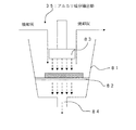
図8は上記したアルカリ成分抽出部35の構成を示す図である。
容器81内には焼却灰が載置されるメッシュ状の載置部82が設けられている。載置部82の上部には載置部82に載置された焼却灰に向けて高圧で高温の水蒸気(装置内又はボイラーから供給)を噴出するノズル83が配置されている。そして、ノズル83から噴出された水蒸気が焼却灰からアルカリ成分を抽出し、載置部82を通過して容器81の下に落ちる。容器81の底面には排出孔84が設けられていて、これらのアルカリ性の水溶液は排出孔84から排出され、アルカリ性水処理装置37に送られる。なお、真空炉33とアルカリ成分抽出部35との間をベルトコンベアを介して焼却灰を搬送し、更に載置部82自体を容器81から搬送する構成とすることで、人手を介することなく一連の処理を行うことができる。
【0068】
焼却灰からアルカリ成分を抽出する手段としては、例えば焼却灰を煮沸するような構成としてもよい。
【0069】
図9は本システム1における排出処理系の構成を示す図である。
このシステム1においては、減圧熱分解炉22、ガスエンジン25、ガス洗浄装置39から排気される排気ガス及びアルカリ成分抽出部35、アルカリ性水処理装置37から排出されるアルカリ水溶液を、乾燥炉91及びバグフィルタ92を介し、排気ファン93により外部に排出している。乾燥炉91及びバグフィルタ92を介することで排気ガス及びアルカリ水溶液からアルカリ成分を回収している。
【0070】
次に、本発明の効果を確認するために行った実験結果を以下に示す。
図10は焼却灰を減圧下で加熱処理するとアルカリ成分が減少することを確認するために行った実験結果である。未処理品のP.H.値が13.2等であるのに対して減圧下(5×10⁻¹〜10torr)1000℃で5時間加熱処理した焼却灰のP.H.値が9.1となり、かなり低下しているのが分かる。
【0071】
また、同実験で同時に行った残渣及び廃ガス等の残留ダイオキシンの分析結果は同図における減圧800℃処理と800℃N2ガス常圧処理では残渣中にダイオキシンは検出されず、廃ガス中には800℃N2ガス常圧処理ではアルカリ処理してもダイオキシンが残留していたのに対して減圧800℃処理更に減圧1000℃処理では残渣中にも廃ガス中にもダイオキシンは検出されなかった。
【0072】
これは減圧では還元性があり、塩素などの分解が早くなること、及びアルカリ蒸発成分が常圧よりも多いため蒸発ガス中で中和反応が起きる確率が高いためである。
【0073】
また、処理前の焼却灰には、鉛及び鉛の化合物が2.4mg/l、銅及び銅の化合物が0.04mg/l、亜鉛及びその化合物0.05mg/l含まれていた。これに対して、減圧下(5×10−1〜10torr)1000℃で加熱処理した焼却灰には、銅及び銅の化合物が0.01mg/lが含まれるだけとなった。また、減圧下(5×10−1〜10torr)800℃で加熱処理し、塩素成分が除去されていない空気で800℃で燃焼し、その後該空気で冷却した焼却灰には、銅及び銅の化合物が0.01mg/l、六価クロムが0.53mg/lが含まれるだけとなった。更に、減圧下(5〜10torr)1000℃で加熱処理し、塩素成分が除去された空気で800℃で燃焼し、その後該空気で冷却した焼却灰には、これらの金属が含まれていなかった。
【0074】
また、焼却灰に代えて土壌について同様の処理を行ったところ、未処理の土壌には0.008mg/lの鉛及びその化合物が含まれており、1000℃で真空蒸発処理した土壌には0.012mg/lの鉛及びその化合物、0.001mg/lのカドミウム及びその化合物が含まれており、1000℃で真空蒸発処理して1000℃で酸化処理した土壌には鉛及びその化合物もカドミウム及びその化合物も含まれていなかった。
【0075】
本発明は上述した実施の形態に限定されるものではない。
例えば、上述した実施の形態は、本発明をシュレッダーダストのエネルギーを利用して焼却灰を無害化する処理システムに適用したものであったが、シュレッダーダストの他に廃家電、廃プラスチック、廃材、紙、油等に適用することができ、焼却灰の他に焼却灰、土壌、汚泥等に適用できる。
【0076】
また、上記実施の形態では焼却灰に対して加熱処理後にアルカリ成分を抽出するものであったが、アルカリ成分を抽出した後に加熱処理するようにしても構わない。このようにすると、10%前後の処理量が減量され、処理設備コストが安く、エネルギーコストも低減できる。しかも、中和アルカリ剤として、NaOHやCa(OH)2等のアルカリ剤を使用しなくてすむ。
【0077】
更に、上記実施形態では、アルカリ成分の抽出を常圧状態で行うものであったが、減圧中でアルカリ成分を抽出するように構成しても構わない。減圧中で処理すると沸点が低下するためにエネルギーコストを低減することができる。
【0078】
また、真空炉33は、図11に示すように、気密室62と冷却室63との間に酸化処理室70を設け、燃焼による酸化処理を冷却室63と別の室で行うように構成してもよい。これにより、これにより効率よく酸化処理及び冷却処理が行える。減圧分解炉22についても同様の構成とすることができる。
【0079】
更に、上記実施形態では、加熱処理を減圧下で行っていたが、常圧で加熱処理するものであっても本発明を適用できる。
【0080】
【発明の効果】
以上説明したように、本発明によれば、有機ハロゲン化物が発生することもなく、重金属を含有する処理対象物体を無害化し、更には処理後の処理対象物体を有効に再利用することがきる。
【図面の簡単な説明】
【図1】本発明の一実施形態に係る処理システムの概略構成を示す図である。
【図2】図1に示した第1の処理系の構成を示す図である。
【図3】図1に示した第2の処理系の構成を示す図である。
【図4】図2に示した減圧熱分解炉の構成を示す図である。
【図5】図2に示したガス処理系の構成を示す図である。
【図6】図3に示した真空炉の構成を示す図である。
【図7】図2及び図3に示したフィルタの構成を示す図である。
【図8】図3に示したアルカリ成分抽出部の構成を示す図である。
【図9】本システムにおける排出処理系の構成を示す図である。
【図10】本発明の効果を確認するために行った実験結果である。
【図11】本発明の他の実施形態に係る真空炉の構成を示す図である。
【符号の説明】
11 処理システム
12 第1の処理系
13 第2の処理系
22 減圧熱分解炉
24 ガス処理系
28、34 フィルタ
33 真空炉
35 アルカリ成分抽出部
37 アルカリ性水処理装置
54 ガス洗浄装置[0001]
BACKGROUND OF THE INVENTION
The present invention relates to a processing apparatus, a processing method, and a method for producing a detoxified object to be treated, which can detoxify, for example, incineration ash.
[0002]
[Prior art]
In recent years, the diffusion and influence of organic halides such as dioxin, PCB, coplana PCB, and heavy metals such as Pb into the environment have become a major social problem. For example, harmful organic halides such as dioxin, PCB, and coplanar PCB, and heavy metals such as Pb remain in residues obtained by burning and pyrolyzing waste, incineration ash, soil, sludge, and the like.
[0003]
For example, as a method of removing harmful substances including organic halides, a method of reducing the concentration of organic halides by heating high-temperature heating residues containing organic halides or by melting them at a high temperature of about 1500 ° C. Has been proposed.
[0004]
[Problems to be solved by the invention]
However, such a method has a problem that heavy metals such as Pb cannot be sufficiently removed.
[0005]
Further, according to the considerations of the present inventors, since the incinerated ash after the treatment as described above contains an alkali component, even if heavy metals are removed without generating organic halides. It has been found that there is a problem in reusing such incineration ash. For example, when incinerated ash containing a large amount of alkali components is reused for cement or brick, the cement or brick may cause an alkali reaction to expand and break.
[0006]
The main object of the present invention is to provide a processing apparatus and a processing method capable of detoxifying an object to be treated containing heavy metal without generating an organic halide, and further effectively reusing the object to be treated after treatment. Another object of the present invention is to provide a method for producing a detoxified object to be treated.
[0007]
[Means for Solving the Problems]
In order to solve such a problem, the processing apparatus of the present invention heats the object to be processed, and oxidizes the heat-treated object to be processed using air from which the chlorine component has been removed, and performs a cooling process. Means, and extraction means for extracting an alkali component from the cooled object to be treated. Alternatively, the present invention provides an extraction means for extracting an alkali component from the object to be treated, a heating means for heat-treating the object to be treated from which the alkali component has been extracted, and removing a chlorine component from the heat-treated object to be treated. And a means for performing a cooling treatment using oxidized air.
Here, the object to be treated includes, for example, incineration ash, soil, sludge and the like.
[0008]
In the present invention, since the heat-treated object to be treated is oxidized using air, the heavy metal is oxidized and rendered harmless. Further, since the chlorine component is removed from the air, when the object to be treated is cooled using the air, it hardly reacts with carbon or the like contained in the object to be treated to generate an organic halide. . Furthermore, since the alkali component is extracted from the object to be treated that has been cooled, the object to be treated and the alkali extract can be effectively reused.
[0009]
In the treatment apparatus of the present invention, the heating means heat-treats the object to be treated under reduced pressure. By subjecting the object to be treated to heat treatment under reduced pressure, alkali components and heavy metals can be extracted from the object to be treated. Further, although it is conceivable to heat and melt the object to be treated near normal pressure, since the melting point is high, there is a problem that expensive and large-scale equipment is required and the running cost is high. On the other hand, since the boiling point decreases and harmful metals and gases can be removed by heat-treating the object to be treated under reduced pressure, the above problem is solved.
[0010]
The processing apparatus of the present invention includes a thermal decomposition means for thermally decomposing a first object to be processed, a decomposition gas extraction means for extracting a decomposition gas generated during the thermal decomposition, and the first process subjected to the thermal decomposition. Heating means for heat-treating the target object (for example, containing carbon) and the second process target object, and the heat-treated first and second process target objects using the air from which chlorine components have been removed Means for oxidizing and cooling, alkali component extracting means for extracting alkali components from the cooled first and second objects to be treated, and extracted by the cracked gas extracting means by the extracted alkali components And neutralizing means for neutralizing the cracked gas. If there is a risk that harmful heavy metals remain in the heated residue even after cooling with air, the oxidation treatment may be performed immediately after the decompression treatment and then the cooling treatment.
[0011]
Here, the first object to be processed includes car shredder dust, waste home appliances, waste plastic, waste materials, paper, oil, and the like. In addition, examples of the second processing target object include incineration ash, soil, and sludge.
[0012]
In the present invention, as described above, the heavy metals and the like in the first and second objects to be processed that have been heat-treated are oxidized using air after vacuum evaporation recovery, for example, so that the heavy metals are oxidized and rendered harmless. Is done. In addition, since the chlorine component is removed from the air, when the first and second objects to be treated are cooled using the air, they react with the carbon contained in the object to be treated, and organic halides are generated. Never do. Furthermore, since the alkali component is extracted from the first and second processing target objects that have been subjected to the cooling process, the first and second processing target objects can be effectively reused. In addition, according to the present invention, the cracked gas extracted by the cracked gas extracting means is neutralized by the alkali component extracted by the alkali component extracting means, so that the cracked gas is effectively reused as a clean gas. be able to. Moreover, the alkali-dissolved metal or the like of the object to be treated can be dissolved and removed with this alkaline extract.
[0013]
In the processing apparatus of the present invention, the thermal decomposition means thermally decomposes the first object to be processed under a reduced pressure that is not more than an explosion limit. Thereby, a 1st process target object can be thermally decomposed efficiently and safely.
[0014]
In the treatment apparatus of the present invention, the heating means heat-treats the first and second object to be treated under reduced pressure. As a result, dioxins and coplanar P.I. C. In the same manner as described above, an alkali component can be extracted from the first and second objects to be treated, and the alkali component is used and generated in the apparatus by an alkali evaporant. It can neutralize toxic oxidant gas, etc., and can be cheap and small-scale equipment, and the running cost can be reduced.
[0015]
In the treatment apparatus of the present invention, the heating means heat-treats using the cracked gas extracted by the cracked gas extracting means and neutralized by the neutralizing means. Thereby, energy can be reused effectively.
[0016]
In the treatment apparatus of the present invention, the thermal decomposition means heat-treats using the decomposition gas extracted by the decomposition gas extraction means and neutralized by the neutralization means. Thereby, energy can be reused effectively.
[0017]
The processing apparatus of the present invention comprises a processing furnace for performing heat treatment on an object to be processed, and means for supplying air from which chlorine components have been removed into the processing furnace after being subjected to the heat treatment under reduced pressure. Features.
[0018]
In the present invention, the air from which the chlorine component has been removed is supplied to the object to be treated after the heat treatment, so that, for example, heavy metal is oxidized and rendered harmless by combustion, and the organic halide is cooled during cooling with the air. Is unlikely to occur. Further, when an oxidation treatment is not required for cooling, an inert gas such as
[0019]
The treatment apparatus of the present invention comprises means for performing a heat treatment on the object to be treated and means for removing an alkali component from the heat-treated object to be treated.
[0020]
In the present invention, since the alkali component is extracted from the object to be treated that has been cooled, the object to be treated (such as metal dissolution and gas neutralization) can be effectively reused.
[0021]
The heat treatment apparatus of the present invention comprises a means for performing a heat treatment on the object to be treated under reduced pressure, an alkali component evaporated from the object to be treated, an organic halide, and other gas during the heat treatment. And a means for recovering the product after neutralization.
[0022]
The treatment method of the present invention includes a step of heat-treating the object to be treated, and a step of oxidizing the heat-treated object to be treated with air from which chlorine components have been removed (including pure oxygen and a state close to pure oxygen). And a step of cooling the oxidized object to be treated, and a step of extracting an alkali component from the object to be treated that has been cooled.
[0023]
The processing method of the present invention includes a step of thermally decomposing a first object to be processed, a step of extracting a decomposition gas generated during the heat decomposition, the first object to be decomposed and the second object to be decomposed. A step of heat-treating the object to be treated, a step of oxidizing the heat-treated first and second object to be treated with air from which chlorine components have been removed, and the oxidized first and second treatments. A step of cooling the target object, a step of extracting an alkali component from the cooled first and second target objects, and a step of neutralizing the extracted decomposition gas by the extracted alkali component It is characterized by comprising.
[0024]
The treatment method of the present invention includes a step of heat-treating a treatment target object, a step of oxidizing the heat-treated treatment target object with air from which a chlorine component has been removed, and a cooling treatment of the oxidized treatment target object. And a process.
[0025]
The treatment method of the present invention comprises a step of heat-treating a treatment target object and a step of extracting an alkali component from the heat-treated treatment target object.
[0026]
The present invention provides a method for producing a detoxified object to be treated, the step of heat-treating the object to be treated, the step of oxidizing the heat-treated object to be treated with air from which chlorine components have been removed, and the oxidation And a step of cooling the treated object to be treated, and a step of extracting an alkali component from the treated object to be cooled.
[0027]
The present invention provides a method for producing a detoxified object to be treated, the step of thermally decomposing the first object to be treated, the step of extracting cracked gas generated during the pyrolysis, and the pyrolyzed A step of heat-treating the first processing target object and the second processing target object; a step of oxidizing the heat-treated first and second processing target objects with air from which chlorine components have been removed; and the oxidation Cooling the first and second treated objects, extracting the alkali components from the cooled first and second treated objects, and extracting the extracted alkali components And a step of neutralizing the cracked cracked gas.
[0028]
The present invention provides a method for producing a detoxified object to be treated, the step of heat-treating the object to be treated, the step of oxidizing the heat-treated object to be treated with air from which chlorine components have been removed, and the oxidation And a step of cooling the processed object. However, if it can be rendered harmless only by vacuum evaporation, oxidation treatment and oxidation cooling are not required.
[0029]
The present invention provides a method for producing a detoxified object to be treated, comprising the steps of heat-treating the object to be treated and extracting an alkali component from the heat-treated object to be treated. .
[0030]
The present invention comprises a means for performing a heat treatment on the object to be treated under reduced pressure, an alkali component evaporated from the object to be treated and an acidic gas such as organic halide, NOx, SOx during the heat treatment. And a means for recovering the product after neutralization.
[0031]
The above-described method invention also has the same effects as the apparatus invention.
[0032]
DETAILED DESCRIPTION OF THE INVENTION
Hereinafter, embodiments of the present invention will be described with reference to the drawings.
In this embodiment, the present invention is applied to a processing system for detoxifying incinerated ash using the energy of shredder dust.
[0033]
FIG. 1 is a diagram showing a schematic configuration of this processing system.
The treatment system 11 includes a first treatment system 12 that thermally decomposes shredder dust, and a second treatment system 13 that heat-treats the thermally decomposed shredder dust and incineration ash.
[0034]
In the first processing system 12, power generation is performed using the cracked gas generated when the shredder dust is thermally decomposed, and the electric power, the cracked gas (clean gas), and the combustion gas of carbon as a heating residue are second processed. It is used as energy when heat treating incineration ash in the system 13 and also as energy of cracked gas. From the shredder dust thermally decomposed by the first treatment system 12, metal, glass, oxide, and the like are recovered.
[0035]
In the second treatment system 13, the alkali component is extracted from the incinerated ash after the heat treatment, and the aqueous alkali solution is supplied to the first treatment system 12, and the decomposition gas generated in the first treatment system 12 It is used as a neutralizing solution for neutralizing oxidizing substances such as halides, NOx, and SOx. Further, at this time, the alkaline dissolved metal is dissolved and removed simultaneously with the alkaline component.
[0036]
The shredder dust incineration ash thermally decomposed in the first treatment system 12 is heat-treated in the second treatment system 13 together with the directly incinerated ash. The incinerated ash that has been heat-treated by the second processing system 13 and from which alkali components have been extracted is reused as non-polluting inorganic materials for building materials such as cement and bricks, fields, and civil engineering materials. Note that the incineration ash required by the alkali component may not be alkali extracted.
[0037]
FIG. 2 is a diagram showing the configuration of the first processing system 12 described above.
The receiving
[0038]
The reduced
[0039]
In the
[0040]
The
[0041]
The
[0042]
The
[0043]
For example, air near the facility is supplied to the
[0044]
The air from which the chlorine component has been removed through the
[0045]
Incinerated ash generated with hot air in the
FIG. 3 is a diagram showing the configuration of the second processing system 13 described above.
The receiving facility 31 is configured by, for example, a belt conveyor that receives incinerated ash from the outside and transfers the received incinerated ash to the ash silo 32 at the subsequent stage. In the ash silo 32, the incinerated ash transferred from the receiving facility 31 and the first processing system 12 is accumulated.
[0046]
The vacuum furnace 33 is supplied with incineration ash from the ash silo 32 and recovers harmful heavy metals and alkali components by heat-treating the supplied incineration ash under reduced pressure. The vacuum furnace 33 is supplied with, for example, air in the vicinity of equipment as combustion and cooling air through a
[0047]
The alkali component extraction unit 35 extracts an alkali component from the incinerated ash heat-treated in the vacuum furnace 33. The incinerated ash from which the alkali component has been extracted is carried out of the system and reused as described above. In the alkali component extraction part 35, neutral water is supplied and the alkali component is extracted from the incinerated ash using this water. The alkali component is extracted and alkalized, and the aqueous alkali solution is sent to the alkaline
[0048]
The alkaline
[0049]
The
[0050]
FIG. 4 is a diagram showing the configuration of the above-described reduced
The reduced
[0051]
These chambers are separated by a
[0052]
An exhaust system 45 is connected to the purge chamber 41 and the cooling
[0053]
The inside of the hermetic chamber 42 is depressurized to about 1 to 50 torr, more preferably about 20 torr (260 Pascals) by exhausting with the pump 46. Thus, safety can be enhanced by processing at a pressure within the explosion limit.
[0054]
The hermetic chamber 42 is heated by a heating means 47 such as a gas burner at 600 to 1200 ° C., more preferably 800 ° C. The heating means 47 is supplied with clean gas from the
[0055]
In the cooling
[0056]
FIG. 5 is a diagram showing the configuration of the
In the gas high-temperature cracking unit 51, cracking of the cracked gas sent from the reduced
[0057]
In the gas quenching section 52, the cracked cracked gas is rapidly cooled, for example, from about 1000 ° C. to about 100 ° C. within 10 seconds. Such rapid cooling can suppress the generation of organic halides such as dioxins. In this case, it is also a rational method to simultaneously perform the neutralization treatment with the extracted alkaline aqueous solution.
[0058]
The alkaline bag filter 53 neutralizes the acidified decomposition gas by passing the rapidly cooled decomposition gas through caustic soda or slaked lime.
[0059]
In the
[0060]
The cracked gas is stored in the high-pressure gas tank 56 after SOx and the like are removed by the catalytic desulfurization device 55. Clean gas is supplied as energy for combustion from the high-pressure gas tank 56 to the
[0061]
FIG. 6 is a diagram showing the configuration of the vacuum furnace 33 described above.
The vacuum furnace 33 includes a purge chamber 61, an
These chambers are separated by a
[0062]
An exhaust system 65 is connected to the purge chamber 61, the
[0063]
The inside of the
[0064]
The
[0065]
In the cooling chamber 63, when there are a lot of heavy metals and cannot be removed by evaporation under reduced pressure, the incinerated ash that has been heated under reduced pressure in the
[0066]
FIG. 7 is a diagram showing the configuration of the
An input hole 72 for supplying air supplied from, for example, the vicinity of the facility is provided at one end of the cylindrical filter main body 71, and an
[0067]
FIG. 8 is a diagram showing the configuration of the alkali component extraction unit 35 described above.
In the container 81, a mesh-like placement portion 82 on which the incineration ash is placed is provided. A
[0068]
As a means for extracting the alkali component from the incinerated ash, for example, the incinerated ash may be boiled.
[0069]
FIG. 9 is a diagram showing the configuration of the discharge processing system in the
In this
[0070]
Next, the results of experiments conducted to confirm the effects of the present invention are shown below.
FIG. 10 shows the results of an experiment conducted to confirm that the alkaline component decreases when the incinerated ash is heat-treated under reduced pressure. P. of untreated product H. While the value is 13.2 mag, under reduced pressure (5 × 10 -1 P. of incinerated ash heat-treated at 1000 ° C. for 5 hours. H. It can be seen that the value is 9.1, which is considerably lower.
[0071]
In addition, the analysis results of residual dioxins such as residue and waste gas simultaneously performed in the same experiment show that dioxins are not detected in the residue in the reduced pressure 800 ° C. treatment and 800 °
[0072]
This is because it is reducible at reduced pressure, the decomposition of chlorine and the like is accelerated, and there is a high probability that a neutralization reaction will occur in the evaporated gas because there are more alkali evaporation components than normal pressure.
[0073]
The incinerated ash before treatment contained 2.4 mg / l of lead and lead compounds, 0.04 mg / l of copper and copper compounds, and 0.05 mg / l of zinc and its compounds. In contrast, under reduced pressure (5 × 10 -1 10 torr) The incinerated ash heat-treated at 1000 ° C. contained only 0.01 mg / l of copper and a copper compound. Also, under reduced pressure (5 × 10 -1 10 torr) Heat treatment at 800 ° C., burning at 800 ° C. with air from which chlorine components have not been removed, and then cooling with the air contains 0.01 mg / l of copper and a compound of copper, hexavalent Only 0.53 mg / l of chromium was included. Furthermore, incineration ash that was heat-treated at 1000 ° C. under reduced pressure (5 to 10 torr), burned at 800 ° C. with air from which chlorine components had been removed, and then cooled with the air did not contain these metals. .
[0074]
Further, when the same treatment was performed on the soil instead of the incinerated ash, the untreated soil contained 0.008 mg / l of lead and its compound, and the soil subjected to vacuum evaporation at 1000 ° C. was 0. .012 mg / l of lead and its compound, 0.001 mg / l of cadmium and its compound, and the soil subjected to vacuum evaporation at 1000 ° C. and oxidized at 1000 ° C. also contains lead and its compound as cadmium and The compound was not included either.
[0075]
The present invention is not limited to the embodiment described above.
For example, in the embodiment described above, the present invention is applied to a treatment system that detoxifies incineration ash using the energy of shredder dust, but in addition to shredder dust, waste home appliances, waste plastic, waste materials, It can be applied to paper, oil, etc., and can be applied to incineration ash, soil, sludge, etc. in addition to incineration ash.
[0076]
Moreover, in the said embodiment, although the alkali component was extracted after heat processing with respect to incineration ash, you may make it heat-process after extracting an alkali component. In this way, the processing amount of about 10% is reduced, the processing equipment cost is low, and the energy cost can be reduced. Moreover, as neutralizing alkali agents, NaOH and Ca (OH) 2 It is not necessary to use alkaline agents such as.
[0077]
Furthermore, in the said embodiment, although extraction of the alkali component was performed in a normal pressure state, you may comprise so that an alkali component may be extracted in pressure_reduction | reduced_pressure. When the treatment is performed under reduced pressure, the energy cost can be reduced since the boiling point is lowered.
[0078]
Further, as shown in FIG. 11, the vacuum furnace 33 is configured such that an
[0079]
Furthermore, in the said embodiment, although heat processing was performed under pressure reduction, this invention is applicable even if it heat-processes by a normal pressure.
[0080]
【The invention's effect】
As described above, according to the present invention, organic halides are not generated, the object to be treated containing heavy metal can be rendered harmless, and further, the object to be treated after treatment can be effectively reused. .
[Brief description of the drawings]
FIG. 1 is a diagram showing a schematic configuration of a processing system according to an embodiment of the present invention.
2 is a diagram showing a configuration of a first processing system shown in FIG. 1. FIG.
FIG. 3 is a diagram showing a configuration of a second processing system shown in FIG. 1;
4 is a diagram showing a configuration of the reduced pressure pyrolysis furnace shown in FIG. 2. FIG.
FIG. 5 is a diagram showing a configuration of a gas processing system shown in FIG. 2;
6 is a diagram showing a configuration of the vacuum furnace shown in FIG. 3. FIG.
7 is a diagram showing a configuration of the filter shown in FIGS. 2 and 3. FIG.
8 is a diagram illustrating a configuration of an alkali component extraction unit illustrated in FIG. 3. FIG.
FIG. 9 is a diagram showing a configuration of a discharge processing system in the present system.
FIG. 10 shows the results of experiments conducted to confirm the effects of the present invention.
FIG. 11 is a diagram showing a configuration of a vacuum furnace according to another embodiment of the present invention.
[Explanation of symbols]
11 Processing system
12 First treatment system
13 Second processing system
22 Vacuum pyrolysis furnace
24 Gas processing system
28, 34 Filter
33 vacuum furnace
35 Alkali component extraction unit
37 Alkaline water treatment equipment
54 Gas cleaning equipment
Claims (4)
前記第1の処理対象物体の熱分解により生じた酸性ガスを土壌、焼却灰又は汚泥の熱分解により生じたアルカリで中和する手段と
を具備することを特徴とする処理装置。Pyrolysis means for pyrolyzing the first object to be treated containing an organic halide;
And a means for neutralizing the acid gas generated by thermal decomposition of the first object to be processed with alkali generated by thermal decomposition of soil, incinerated ash, or sludge.
前記処理対象物体の熱分解により生じた酸性ガスを土壌、焼却灰又は汚泥の熱分解により生じたアルカリで中和する
ことを特徴とする処理方法。Thermally decompose the object to be treated, including organic halides,
A treatment method comprising neutralizing acid gas generated by thermal decomposition of the object to be processed with alkali generated by thermal decomposition of soil, incinerated ash, or sludge.
有機ハロゲン化物を含む処理対象物体を熱分解する工程と、
前記処理対象物体の熱分解により生じた酸性ガスを土壌、焼却灰又は汚泥の熱分解により生じたアルカリで中和する工程と
を含むことを特徴とする無害化した処理対象物体の生産方法。In a method for producing a detoxified object to be treated,
A process of thermally decomposing an object to be treated containing an organic halide;
Neutralizing acid gas generated by thermal decomposition of the object to be treated with alkali generated by thermal decomposition of soil, incinerated ash or sludge.
Priority Applications (1)
| Application Number | Priority Date | Filing Date | Title |
|---|---|---|---|
| JP32599899A JP3642995B2 (en) | 1999-11-16 | 1999-11-16 | Processing apparatus, processing method, and method for producing detoxified object to be processed |
Applications Claiming Priority (1)
| Application Number | Priority Date | Filing Date | Title |
|---|---|---|---|
| JP32599899A JP3642995B2 (en) | 1999-11-16 | 1999-11-16 | Processing apparatus, processing method, and method for producing detoxified object to be processed |
Publications (2)
| Publication Number | Publication Date |
|---|---|
| JP2001137824A JP2001137824A (en) | 2001-05-22 |
| JP3642995B2 true JP3642995B2 (en) | 2005-04-27 |
Family
ID=18182967
Family Applications (1)
| Application Number | Title | Priority Date | Filing Date |
|---|---|---|---|
| JP32599899A Expired - Fee Related JP3642995B2 (en) | 1999-11-16 | 1999-11-16 | Processing apparatus, processing method, and method for producing detoxified object to be processed |
Country Status (1)
| Country | Link |
|---|---|
| JP (1) | JP3642995B2 (en) |
Families Citing this family (4)
| Publication number | Priority date | Publication date | Assignee | Title |
|---|---|---|---|---|
| GB0604907D0 (en) | 2006-03-10 | 2006-04-19 | Morgan Everett Ltd | Pyrolysis apparatus and method |
| JP2011173075A (en) * | 2010-02-25 | 2011-09-08 | Nichiyo Engineering Kk | Heat treatment apparatus and heat treatment method |
| JP2014117675A (en) * | 2012-12-18 | 2014-06-30 | Sumitomo Osaka Cement Co Ltd | Method and apparatus for treating exhaust gas |
| CN103350104B (en) * | 2013-07-17 | 2014-09-17 | 中国科学院地理科学与资源研究所 | In-polluted-site heat-intensifying vapor extracting and repairing integrated device and application method |
-
1999
- 1999-11-16 JP JP32599899A patent/JP3642995B2/en not_active Expired - Fee Related
Also Published As
| Publication number | Publication date |
|---|---|
| JP2001137824A (en) | 2001-05-22 |
Similar Documents
| Publication | Publication Date | Title |
|---|---|---|
| JP3395148B2 (en) | Soil production method, soil treatment device, treatment method and treatment device | |
| CN111006221A (en) | System and method for hazardous waste incineration | |
| JPWO1999051366A1 (en) | Soil production method, soil treatment device, treatment method and treatment device | |
| JP3642995B2 (en) | Processing apparatus, processing method, and method for producing detoxified object to be processed | |
| JP2002205049A (en) | Purification methods and facilities for contaminated soil | |
| JPH08229533A (en) | Waste volume reduction processing method | |
| JP3886970B2 (en) | Recycling method of wood | |
| JP4507468B2 (en) | Powder plasma processing method and processing apparatus therefor | |
| CN214791158U (en) | Useless processing system of fluorine-containing danger | |
| JP3926290B2 (en) | Processing apparatus and processing method | |
| RU2147713C1 (en) | Method of thermal reworking of solid wastes | |
| JP2000167514A (en) | Exhaust gas treatment method to reduce dioxin emission | |
| JPWO2002038252A1 (en) | Processing device and processing method | |
| JP3248319B2 (en) | Fly ash treatment method and device for refuse incinerator | |
| JP3310245B2 (en) | Processing device and processing method | |
| JP3818936B2 (en) | Processing equipment | |
| JP3727908B2 (en) | Soil treatment method | |
| CN216513678U (en) | Paint slag harmless treatment device | |
| JP3951587B2 (en) | Pyrolysis treatment facility and operation method | |
| JPH0979531A (en) | Detoxification treatment method of PCB adhesion transformer | |
| JP2000271440A (en) | Method and apparatus for decomposing and removing harmful substances in exhaust gas | |
| JP2002273396A (en) | Composite aluminum sash recycling method and equipment | |
| JP3949662B2 (en) | PCB processing method and PCB processing apparatus | |
| JP2005058979A (en) | Hazardous substance detoxification equipment | |
| JP2006101979A (en) | Detoxification treatment method for polychlorinated biphenyls |
Legal Events
| Date | Code | Title | Description |
|---|---|---|---|
| TRDD | Decision of grant or rejection written | ||
| A01 | Written decision to grant a patent or to grant a registration (utility model) |
Free format text: JAPANESE INTERMEDIATE CODE: A01 Effective date: 20050125 |
|
| A61 | First payment of annual fees (during grant procedure) |
Free format text: JAPANESE INTERMEDIATE CODE: A61 Effective date: 20050126 |
|
| R150 | Certificate of patent or registration of utility model |
Free format text: JAPANESE INTERMEDIATE CODE: R150 |
|
| FPAY | Renewal fee payment (event date is renewal date of database) |
Free format text: PAYMENT UNTIL: 20090204 Year of fee payment: 4 |
|
| FPAY | Renewal fee payment (event date is renewal date of database) |
Free format text: PAYMENT UNTIL: 20100204 Year of fee payment: 5 |
|
| FPAY | Renewal fee payment (event date is renewal date of database) |
Free format text: PAYMENT UNTIL: 20110204 Year of fee payment: 6 |
|
| FPAY | Renewal fee payment (event date is renewal date of database) |
Free format text: PAYMENT UNTIL: 20110204 Year of fee payment: 6 |
|
| FPAY | Renewal fee payment (event date is renewal date of database) |
Free format text: PAYMENT UNTIL: 20120204 Year of fee payment: 7 |
|
| FPAY | Renewal fee payment (event date is renewal date of database) |
Free format text: PAYMENT UNTIL: 20120204 Year of fee payment: 7 |
|
| FPAY | Renewal fee payment (event date is renewal date of database) |
Free format text: PAYMENT UNTIL: 20130204 Year of fee payment: 8 |
|
| FPAY | Renewal fee payment (event date is renewal date of database) |
Free format text: PAYMENT UNTIL: 20130204 Year of fee payment: 8 |
|
| FPAY | Renewal fee payment (event date is renewal date of database) |
Free format text: PAYMENT UNTIL: 20140204 Year of fee payment: 9 |
|
| R250 | Receipt of annual fees |
Free format text: JAPANESE INTERMEDIATE CODE: R250 |
|
| R250 | Receipt of annual fees |
Free format text: JAPANESE INTERMEDIATE CODE: R250 |
|
| R250 | Receipt of annual fees |
Free format text: JAPANESE INTERMEDIATE CODE: R250 |
|
| LAPS | Cancellation because of no payment of annual fees |