JP3655155B2 - Manifold valve structure - Google Patents
Manifold valve structure Download PDFInfo
- Publication number
- JP3655155B2 JP3655155B2 JP36539599A JP36539599A JP3655155B2 JP 3655155 B2 JP3655155 B2 JP 3655155B2 JP 36539599 A JP36539599 A JP 36539599A JP 36539599 A JP36539599 A JP 36539599A JP 3655155 B2 JP3655155 B2 JP 3655155B2
- Authority
- JP
- Japan
- Prior art keywords
- valve
- block
- opening
- fluid chamber
- fluid
- Prior art date
- Legal status (The legal status is an assumption and is not a legal conclusion. Google has not performed a legal analysis and makes no representation as to the accuracy of the status listed.)
- Expired - Lifetime
Links
Images




Landscapes
- Valve Housings (AREA)
- Multiple-Way Valves (AREA)
Description
【0001】
【発明の属する技術分野】
この発明は、マニホールド弁構造体に関する。
【0002】
【従来の技術】
例えば、工場等で、配管に純水等の流体を流し、所定の作業場所へ供給する場合がある。その際、目的とする作業や製品に応じて、前記純水等の流体に必要となる薬品等を所定流量で混入して主流体として供給するため、あるいは前記主流体等の一の流体を複数の場所へ分配して供給するため、配管の途中に図13及び図14に示すようなマニホールド弁構造体50を接続することがある。
【0003】
前記マニホールド弁構造体50は、略直方体の本体ブロック51と弁機構60を備える副ブロック55よりなる。
前記本体ブロック51には、その長手方向に所定間隔でもって複数の本体側連通開口52が本体ブロック51の上面から本体ブロック51内に下向きに形成されている。該本体側連通開口52の下端位置には本体ブロック51の長手方向に沿う水平方向の主流体流路53が形成されており、該主流体流路53と本体側連通開口52とが通じている。なお、前記主流体流路53の両端の少なくとも一方(図示の例では片方)には配管等との接続口となる主流体流出入口54が設けられ、該主流体流出入口54は弁構造体50外に開口している。
【0004】
一方、副ブロック55は、前記本体ブロック51の上面に複数個(図示の例では3個)並設されている。それぞれの副ブロック55の下部には、前記本体側連通開口52の上端と一連に通じる副ブロック側連通開口56が上下方向に形成されると共に、該副ブロック側連通開口56の上端と弁機構60の下部を介して通じる副流体(純水や薬品等)のための副流体流出入口57が副ブロック55の正面または背面から水平方向に形成されている。また、前記弁機構60はエアーにより上昇しスプリング65により下降する弁部61を備える公知のもので、前記弁部61が副ブロック側連通開口56を開閉するように設けられている。符号62はダイアフラムである。
【0005】
前記構造のマニホールド弁構造体50は、前記副流体流出入口57に薬品等の供給装置が接続される。そして、必要に応じて副ブロック55の弁機構60を適宜作動させて前記副ブロック側連通開口56を開放すれば、所定量の副流体を副ブロック側連通開口56及び本体ブロック側連通開口52を通して主流体流路53内に供給できる。また、複数の副流体を切り替えて供給する場合には、該当する他の副ブロック側連通流路の上端をそれと対応する弁機構60の作動によって開ければよい。
【0006】
しかしながら、前記従来のマニホールド弁構造体50にあっては、ユーザーのニーズに合わせて、供給する副流体の数等に対応できるように、言い換えれば、組み合わせる副ブロック55(副流体流出入口57)の数に合致するするように、その都度本体ブロック51を設計しなければならず、汎用性に劣っていた。また、工場等へのマニホールド弁構造体の設置後、供給する副流体の数を増減させる必要が生じたときには、本体ブロック51を新たに設計変更して取り替える必要が生じるので、手間がかかるとともにコスト的に不利であった。
【0007】
加えて、前記従来構造では、配管等との接続口となる主流体流出入口54と副流体流出入口57は、図示の如く互いに直交する方向に形成されるのが一般的である。その結果、マニホールド弁構造体50外における主流体の流れ方向と副流体の流れ方向とが平行になるようにマニホールド弁構造体50を設置する場合には、当該マニホールド弁構造体50の設置スペースを広くとる必要が生じる等、制約を受けることがあった。詳しくは、当該マニホールド弁構造体50の主流体流出入口57を、図12の(B)のように、該弁構造体外の副流体の流れ方向に平行な、つまり前記主流体流路53に直交する配管Pに接続する場合には、図示の如く継ぎ手R等により流体の流れを変換する必要が生じ、その継ぎ手R分無駄なスペースができてしまう。
【0008】
【発明が解決しようとする課題】
本発明は前記の点に鑑みて提案されたものであって、汎用性に優れるとともに、設置後において供給する副流体の数等を変更する場合にも簡単かつ迅速に対応でき、コスト的にも有利なマニホールド弁構造体を提供しようとするものである。
【0009】
【課題を解決するための手段】
すなわち、請求項1の発明は、ブロック背面(20b)に形成された第1流体のための第1流出入口(22)と第1弁開口(23)とを有する第1流体チャンバ(21)と、前記第1弁開口(23)を介して連通されブロック側面のいずれか(20d)に形成された主流体のための第1連通開口(26)を有する第1主流体チャンバ(25)と、前記第1弁開口(23)を開閉する第1弁機構(V1)を備える第1弁ブロック(20)と、ブロック背面(30b)に形成された第2流体のための第2流出入口(32)と第2弁開口(33)とを有する第2流体チャンバ(31)と、前記第2弁開口(33)を介して連通されブロック側面のいずれか(30c)に形成された主流体のための第2連通開口(36)を有する第2主流体チャンバ(35)と、前記第2弁開口(33)を開閉する第2弁機構(V2)を備える第2弁ブロック(30)とからなり、前記第1弁ブロックの第1主流体チャンバ(25)または前記第2弁ブロックの第2主流体チャンバ(35)の少なくとも一方の弁ブロック(20,30)の正面(20a,30a)に主流体流出入口(27)が形成されるとともに、前記第1弁ブロックの第1連通開口(26)と前記第2弁ブロックの第2連通開口(36)とが互いに連通して連結配置されていることを特徴とするマニホールド弁構造体(10)に係る。
【0010】
また、請求項2の発明は、ブロック背面(20b)に形成された第1流体のための第1流出入口(22)と第1弁開口(23)とを有する第1流体チャンバ(21)と、前記第1弁開口(23)を介して連通されブロック側面のいずれか(20d)に形成された主流体のための第1連通開口(26)を有する第1主流体チャンバ(25)と、前記第1弁開口(23)を開閉する第1弁機構(V1)を備える第1弁ブロック(20)と、ブロック背面(30b)に形成された第2流体のための第2流出入口(32)と第2弁開口(33)とを有する第2流体チャンバ(31)と、前記第2弁開口(33)を介して連通されブロック側面のいずれか(30c)に形成された主流体のための第2連通開口(36)を有する第2主流体チャンバ(35)と、前記第2弁開口(33)を開閉する第2弁機構(V2)を備える第2弁ブロック(30)と、ブロック背面(40b)に形成された第3流体のための第3流出入口(42)と第3弁開口(43)とを有する第3流体チャンバ(41)と、前記第3弁開口(43)を介して連通されブロック側面の両側(40c,40d)に形成された主流体のための第3連通開口(46)及び第4連通開口(47)を有する第3主流体チャンバ(45)と、前記第3弁開口(43)を開閉する第3弁機構(V3)を備える第3弁ブロック(40)とからなり、前記第1弁ブロックの第1主流体チャンバ(25)、前記第2弁ブロックの第2主流体チャンバ(35)、前記第3弁ブロックの第3主流体チャンバ(45)の少なくとも一つの弁ブロック(20,30,40)の正面(20a,30a,40a)に主流体流出入口(27)が形成されるとともに、前記第1弁ブロックの第1連通開口(26)と前記第3弁ブロックの第3連通開口(46)と、及び前記第2弁ブロックの第2連通開口(36)と前記第3弁ブロックの第4連通開口(47)とがそれぞれ連通して連結配置されていることを特徴とするマニホールド弁構造体(10B)に係る。
【0011】
さらに、請求項3の発明は、請求項2において、前記第3弁ブロック(40)を複数備え、隣接する第3弁ブロック(40)の第3連通開口(46)と第4連通開口(47)とが連通して連結配置されているマニホールド弁構造体(10C)に係る。
【0012】
【発明の実施の形態】
以下添付の図面に従ってこの発明を詳細に説明する。
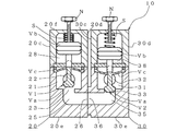
図1は請求項1の発明の一実施例に係るマニホールド弁構造体を示す正面図、図2は図1の2−2断面図、図3は図1の3−3断面図、図4は同マニホールド弁構造体のブロック並設方向に沿って切断した断面図、図5は同マニホールド弁構造体におけるブロック連結部分の連通開口周辺を拡大して示す断面図、図6は請求項1に記載した発明の他の実施例に係るマニホールド弁構造体を示す正面図、図7は同マニホールド弁構造体のブロック並設方向に沿って切断した断面図、図8は請求項2の発明の一実施例に係るマニホールド弁構造体を示す正面図、図9は同マニホールド弁構造体のブロック並設方向に沿って切断した断面図、図10は請求項3の発明の一実施例に係るマニホールド弁構造体を示す正面図、図11は同マニホールド弁構造体のブロック並設方向に沿って切断した断面図、図12は図8のマニホールド弁構造体の配管等との接続例を従来構造と比較して示した概略図である。
【0013】
〔請求項1の発明〕
図1ないし図4に示すマニホールド弁構造体10は、請求項1の発明の一実施例に係るものであり、第1弁ブロック20と第2弁ブロック30とからなる。このマニホールド弁構造体10は、工場等で、純水等の流体を所定の作業場所へ供給する配管の途中等に接続され、前記純水等に薬品等を所定流量で混合して主流体として供給したり、あるいは所定流体を複数の場所へ分配して供給したりするのに使用される。なお、図2及び図3は図1の2−2線、3−3線でそれぞれ切断した断面図であるが、理解を容易にするために、各弁ブロック20,30を後述する作動流体流通口28a,28b,38a,38bを通って切断している。
【0014】
第1弁ブロック20は、図のような略直方体に形成され、第1流体チャンバ21と第1主流体チャンバ25と第1弁機構V1を備えている。なお、この実施例では、図示から理解されるように、前記第1流体チャンバ21は第1弁ブロック20の略中央に位置し、該第1流体チャンバ21の下方に前記第1主流体チャンバ25が位置している。
【0015】
前記第1流体チャンバ21は、第1流体(純水や薬品等)のための第1流出入口22と第1弁開口23を有している。前記第1流出入口22は、当該第1弁ブロック20における第1流体が流出入する部分であり、第1弁ブロック20の正面20a,背面20b,第2弁ブロック30の反対側の側面20c,下面20eの何れか(図示の例では背面20b)から略水平方向に形成されている。また、前記第1弁開口23は、第1主流体チャンバ25に連通するように、前記第1流出入口22と直交する略鉛直方向(上下方向)に形成されている。なお、この実施例では、前記第1流体チャンバ21内には、後述するように第1弁機構V1の弁部Vaが配され、当該第1流体チャンバ21は弁室を構成している。
【0016】
第1主流体チャンバ25は、前記第1弁開口23を介して第1流体チャンバ21と連通するように形成され、主流体のための第1連通開口26と主流体流出入口27を有している。前記第1連通開口26は、後述する第2弁ブロック30の第2連通開口36と連通する部分であり、第1弁ブロック20の第2弁ブロックに対向する側面(図の右側面)20dから略水平方向に形成されている。また、前記主流体流出入口27は、当該弁構造体10における主流体が流出入する部分であり、第1弁ブロック20の正面20a,背面20b,第2弁ブロックの反対側の側面(図の左側面)20c,下面20eの何れか(図示の例では前記第1流出入口22とは反対側となる正面20a)から略水平方向に形成されている。
【0017】
また、前記第1流体チャンバ21または第1主流体チャンバ25の何れか、実施例では第1流体チャンバ21には、前記第1弁開口23を開閉する第1弁機構V1が配設されている。この第1弁機構V1としては、前記第1流体チャンバ21内を適宜手段により上下動する弁部を備えたものが用いられる。
【0018】
実施例では、前記第1弁機構V1は、第1流体チャンバ21内を上下動する弁部Vaと、該弁部Vaの上部に固着され前記第1流体チャンバ21上方の第1調圧室28内を上下動するピストン部Vbとを有し、そのピストン部Vb上面と第1調圧室28の内壁間にはスプリングSが介在され、当該ピストン部Vbは下方向へ付勢されている。そして、前記第1調圧室28のピストン部Vbより下方の空間にエアー等の作動流体を流入させることにより前記ピストン部Vb及び弁部Vaが上昇し、反対に前記空間から作動流体を流出させると前記スプリングSの弾性力により前記ピストン部Vb及び弁部Vaが下降する。また、実施例の第1弁機構V1においては、前記弁部Vaの上部にダイヤフラム部Vcが設けられている。さらに、実施例では、第1弁ブロック20の上面20fに調節ネジ部材Nが螺着され、該調節ネジ部材Nの回動によりピストン部Vb上面と第1調圧室28の内壁間の距離(ピストン部Vbが上死点に位置する場合における距離)を変え、それにより前記弁部Vaと第1弁開口23間の開度を微調整できるようになっている。なお、図中の符号28a,28bは前記第1弁機構V1を上下動させるエアー等の作動流体を第1調圧室28内に流通させるための作動流体流通口である。
【0019】
前記第1弁機構V1は、適当な制御装置(図示せず)と接続されており、第1流体あるいは主流体の所要供給量に合わせて前記弁部Vaが上下動することによって、前記第1弁開口23を開閉し、第1流体チャンバ21の第1流出入口22から流入する第1流体を第1主流体チャンバ25内へ供給しまたは供給を停止し、あるいは第1主流体チャンバ25の主流体流出入口27から流入する流体を第1流体チャンバ21内へ供給しまたは供給を停止する。
【0020】
第2弁ブロック30は、前記第1弁ブロック20と同様に、図のような略直方体に形成され、第2流体チャンバ31と第2主流体チャンバ35と第2弁機構V2を備えている。なお、この実施例では、図示から理解されるように、前記第2流体チャンバ31は第2弁ブロック30の略中央に位置し、該第2流体チャンバ31の下方に前記第2主流体チャンバ35が位置している。
【0021】
前記第2流体チャンバ31は、第2流体のための第2流出入口32と第2弁開口33を有している。前記第2流出入口32は、当該第2弁ブロック30における第2流体が流出入する部分であり、第2弁ブロック30の正面30a,背面30b,第1弁ブロックの反対側の側面(図の右側面)30d,下面30eの何れか(図示の例では背面30b)から略水平方向に形成されている。また、前記第2弁開口33は、第2主流体チャンバ35に連通するように、前記第2流出入口32と直交する略鉛直方向に形成されている。なお、この実施例では、前記第2流体チャンバ31内には、後述する第2弁機構V2の弁部Vaが配され、当該第2流体チャンバ31は弁室を構成している。
【0022】
第2主流体チャンバ35は、前記第2弁開口33を介して第2流体チャンバ31と連通するように形成され、主流体のための第2連通開口36を有している。前記第2連通開口36は、前記第1弁ブロック20の第1連通開口26と連通する部分であり、第2弁ブロック30の第1弁ブロック20に対向する側面(図の左側面)30cから略水平方向に形成されている。
【0023】
また、前記第2流体チャンバ31または第2主流体チャンバ35の何れか、実施例では第2流体チャンバ31には、前記第2弁開口33を開閉する第2弁機構V2が設けられている。この第2弁機構V2は前記第1弁機構V1と同じ構成のものが用いられるので、図示において前記第1弁機構V1の部材と同一部材については同一符号を付し、その説明を省略する。なお、図中の符号38は第2弁ブロック30の第2流体チャンバ31上方に形成される第2調圧室、38a,38bは第2弁機構V2を上下動させるエアー等の作動流体を第2調圧室38内に流通させるための作動流体流通口である。
【0024】
ここで、前記第1弁機構V1と第2弁機構V2は、各流体毎に供給及び供給停止の切り替えや供給量の増減の調整を行えるよう互いに独立して作動できるようにしたり、あるいは各流体の同時供給や交互供給の場合等に対応できるよう各弁機構同士を関連させて作動できるようにしてもよい。このように各弁機構を関連させて作動させる一方法としては、図示しないコンピュータ制御装置等を介して作動流体供給装置を前記作動流体流通口28a,28b,38a,38bと接続する方法がある。
【0025】
前記各弁ブロック20,30及び弁機構V1,V2の弁部VaやダイヤフラムVc等流体と接触する部分の材質は、主流体及び副流体の種類によって適宜選択されるが、酸やアルカリ等に対する耐性を有するPTFE(ポリテトラフルオロエチレン)等が好適である。
【0026】
このマニホールド弁構造体10においては、前記第1弁ブロック20及び第2弁ブロック30を、それらの連通開口26,36を有する側面20d,30cが連結面となるように連結される。これにより、前記第1弁ブロック20の第1連通開口26と第2弁ブロック30の第2連通開口36とが互いに連通して連結配置され、第1弁ブロック20の第1主流体チャンバ25と第2弁ブロック30の第2主流体チャンバ35が一体になる。
【0027】
前記各ブロック20,30の連結は、各ブロック側面から螺着されるボルト等の緊締部材(図示せず)を用いて行われるが、マニホールド弁構造体10の使用に際して漏れのないよう当該連結を密に行う必要がある。この実施例では、図5の(A)に示すように、前記第1弁ブロック20の第2弁ブロック側側面20dの第1連通開口26外周には該第1連通開口26を取り囲むように環状凹溝部29aが形成され、これに対して、前記第2弁ブロック30の第1弁ブロック側側面30cの第2連通開口36周縁には環状突起39aが突設され、さらに環状突起39aの外周には前記環状凹溝部29に収容される頭部39cと前記環状凹溝部29aの内周縁部29bに当接するテーパ面39dとを有する環状突部39bが形成されていて、当該両弁ブロック20,30の連結時、すなわち前記緊締部材の緊締時には、図5の(B)に示すように、前記第2弁ブロック30の環状突起39aが前記第1弁ブロック20の第1連通開口26周縁に圧着されるとともに、前記第弁2ブロック30の環状突部39bが前記環状凹溝部29aに収容されかつ前記環状突部39bのテーパ面39dが前記環状凹溝部29aの内周縁部29bに圧着されるようになっている。このようにすれば実に密に両弁ブロック20,30を連結できる。勿論、これに限らず、当該弁ブロックの連結に際して両弁ブロック間にシールパッキン等を介設する等してシール性を高めるシール構造を適用してもよい。
【0028】
次に、かかる構造のマニホールド弁構造体10の作動について説明する。なお、各流体供給時の異なる時点の作動を一度に視覚的に確認できるようにするため、図4ではマニホールド弁構造体10の2つの弁機構V1,V2が第1流体あるいは第2流体供給時の異なった時点の位置を同時に示している。
【0029】
まず、当該マニホールド弁構造体10を、純水や薬品等の副流体(実施例では第1流体と第2流体に相当する。)を所定流量で混合して主流体として供給するために用いる場合における作動について述べる。最初に、前記第1流出入口22または第2流出入口32からマニホールド弁構造体10内に入った第1流体または第2流体は、前記第1流体チャンバ21または第2流体チャンバ31を満たす。次いで、弁機構V1,V2の弁部Vaが上昇し、前記第1弁開口23または第2弁開口33が開くと所定流量の各流体が前記第1主流体チャンバ25または第2主流体チャンバ35内に供給される。ここで、前記第2主流体チャンバ35内に供給された第2流体は前記第2連通開口36,第1連通開口26を介して第1主流体チャンバ25内に流入し、該第1主流体チャンバ25内で第1流体と第2流体とが混合される。そして、その混合流体が主流体として前記第1主流体チャンバ25の第1主流体流出入口27から排出される。これに対して、前記エアー等の作動流体の切換により第1弁機構V1または第2弁機構V2の両方または何れか一方の弁部VaがスプリングSのバネ弾性によって下降すると、該弁部Vaに対応する第1弁開口23または第2弁開口33が閉じられ、第1流体または第2流体の第1主流体チャンバ25または第2主流体チャンバ35への供給が停止する。
【0030】
次に、所定流体を複数の場所へ分配して供給するために、当該マニホールド弁構造体10を用いる場合における作動について述べる。最初に、前記第1主流体流出入口27からマニホールド弁構造体10内に入った流体は、前記第1主流体チャンバ25を満たすとともに、その流体は前記第1連通開口26,第2連通開口36を介して第2主流体チャンバ35内に流入する。次いで、前記弁機構V1,V2の弁部Vaが上昇し、前記第1弁開口23及び第2弁開口33が開くと所定流量の流体が前記第1流体チャンバ21及び第2流体チャンバ31内に流入し、その後前記第1流出入口22及び第2流出入口32から弁構造体10外へ流出される。一方、前記エアー等の作動流体の切換により第1弁機構V1または第2弁機構V2の両方または何れか一方の弁部VaがスプリングSのバネ弾性によって下降すると、該弁部Vaに対応する第1弁開口23または第2弁開口33が閉じられ、流体の第1流体チャンバ21または第2流体チャンバ31への流入(供給)が停止する。
【0031】
なお、上記実施例においては、各弁ブロック20,30の第1流体チャンバ21及び第2流体チャンバ31は各主流体チャンバ25,35の上方に位置し、該第1流体チャンバ21及び第2流体チャンバ31内に弁機構V1,V2の弁部Vaが配されているが、これに限らず、図6及び図7に示す他の実施例に係るマニホールド弁構造体10Aの如く、第1流体チャンバ21A及び第2流体チャンバ31Aを第1主流体チャンバ25A及び第2主流体チャンバ35Aの下方に形成し、前記第1主流体チャンバ25A内に第1流体チャンバ21Aの第1弁開口23Aを開閉する第1弁機構V1の弁部Vaを、第2主流体チャンバ35A内に第2流体チャンバ31Aの第2弁開口33Aを開閉する第2弁機構V2の弁部Vaをそれぞれ配してもよい。図示の符号20Aは第1弁ブロック、22Aは第1流体チャンバ21Aの第1流出入口、26Aは第1主流体チャンバ25Aの第1連通開口、27Aは第1主流体チャンバ25Aの主流体流出入口、30Aは第2弁ブロック、32Aは第2流体チャンバ31Aの第2流出入口、36Aは第2主流体チャンバ35Aの第2連通開口である。
【0032】
〔請求項2の発明〕
次に、請求項2の発明について図8及び図9を用いて説明する。図示するマニホールド弁構造体10Bは、請求項2の発明の一実施例に係るものであり、第1弁ブロック20と第2弁ブロック30と該両弁ブロック20,30間に挟まれる第3弁ブロック40からなる。なお、このマニホールド弁構造体10Bの第1弁ブロック20及び第2弁ブロック30の構成は、前記図1ないし図4に示したマニホールド弁構造体10のものと同一であるため、図において同一符号を付し、それらの説明は便宜上省略するものとする。以下、第3弁ブロック40について詳述する。図8中の符号40aは、第3弁ブロック40の正面である。
【0033】
第3弁ブロック40は、前記第1弁ブロック20及び第2弁ブロック30と同様に、図のような略直方体に形成され、第3流体チャンバ41と第3主流体チャンバ45と第3弁機構V3を備えている。なお、この実施例では、図示から理解されるように、前記第3流体チャンバ41は第3弁ブロック40の略中央に位置し、該第3流体チャンバ41の下方に前記第3主流体チャンバ45が位置しているが、前述したマニホールド弁構造体10Aの各弁ブロック20A,30Aの如く、第3主流体チャンバが第3流体チャンバの上方に位置するように両チャンバを形成してもよい。
【0034】
前記第3流体チャンバ41は、第3流体のための第3流出入口42と第3弁開口43を有している。前記第3流出入口42は、第3弁ブロック40における第3流体が流出入する部分であり、第3弁ブロック40の正面,背面,下面の何れか(図示の例では背面40b)から略水平方向に形成されている。前記第3弁開口43は、第3主流体チャンバ45に連通するように、前記第3流出入口42と直交する略鉛直方向に形成されている。
【0035】
第3主流体チャンバ45は、前記第3弁開口43を介して第3流体チャンバ41と連通するように形成され、主流体のための第3連通開口46及び第4連通開口47を有している。前記第3連通開口46は、第1弁ブロック20の第1連通開口26と連通する部分であり、第3弁ブロック40の第1弁ブロック20に対向する側面(図の左側面40c)から略水平方向に形成されている。一方、前記第4連通開口47は、第2弁ブロック30の第2連通開口36と連通する部分であり、第3弁ブロック40の第2弁ブロック30に対向する側面(図の右側面40d)から略水平方向に形成されている。
【0036】
また、前記第3流体チャンバ41または第3主流体チャンバ45の何れか、実施例では第3流体チャンバ41には、前記第3弁開口43を開閉する第3弁機構V3が配設されている。なお、前記したように第3主流体チャンバが第3流体チャンバの上方に位置する場合には、第3主流体チャンバに第3弁機構V3が配設されることになる。前記第3弁機構V3としては、前記第1弁機構V1と同じ構成のものが用いられるので、図示において前記第1弁機構V1の部材と同一部材については同一符号を付し、その説明を省略する。図中の符号48は第3弁ブロック40の第3流体チャンバ41上方に形成される第3調圧室、48a,48bは第3弁機構V3を上下動させるエアー等の作動流体を第3調圧室48内に流通させるための作動流体流通口である。
【0037】
そして、このマニホールド弁構造体10Bにおいては、第1弁ブロック20及び第2弁ブロック30とで第3弁ブロック40を挟むようにボルト等の緊締部材により密に連結されることによって、前記第1弁ブロック20の第1連通開口26と前記第3弁ブロック40の第3連通開口46と、及び前記第2弁ブロック30の第2連通開口36と前記第3弁ブロック40の第4連通開口47とがそれぞれ連通して連結配置され、前記第1主流体チャンバ25,第2主流体チャンバ35,第3主流体チャンバ45が一体となる。なお、この各ブロックを連結する際には、上記したマニホールド弁構造体10のシール構造を適用するのが好ましい。また、このマニホールド弁構造体10Bの作動については上記マニホールド弁構造体10の作動と概ね同じであるので説明は省略する。
【0038】
〔請求項3の発明〕
図10及び図11には、請求項3の発明の一実施例に係るマニホールド弁構造体10Cが示されている。このマニホールド弁構造体10Cは、前記第1弁ブロック20と第2弁ブロック30と複数(図示の例では2つ)の第3弁ブロック40,40からなる。なお、各弁ブロック20,30,40の構成は、前記マニホールド弁構造体10あるいは10Bの構成と同一であるため、図において同一符号を付し、それらの説明は省略する。
【0039】
そして、このマニホールド弁構造体10Cにおいては、第1弁ブロック20及び第2弁ブロック30とで複数の第3弁ブロック40,40を挟むようにボルト等の緊締部材により連結される。これによって、第1弁ブロック20の第1連通開口26と最も第1弁ブロック寄りの第3弁ブロック40の第3連通開口46と、及び前記第2弁ブロック30の第2連通開口36と最も第2弁ブロック寄りの第3弁ブロック40の第4連通開口47と、並びに隣接する第3弁ブロック40の第3連通開口46と第4連通開口47とがそれぞれ連通して連結配置され、前記第1主流体チャンバ25,第2主流体チャンバ35,第2主流体チャンバ45,45が一体となる。なお、このマニホールド弁構造体10Cの作動については上記マニホールド弁構造体10の作動と概ね同じであるので説明は省略する。
【0040】
上で述べてきたように前記各弁ブロック20,30,40をモジュール化すれば、前記第3弁ブロック40の数を適宜選択することにより、様々なユーザーのニーズ、つまり多種多様な副流体の数(あるいは流体を分配供給する作業場所の数)に対応でき、汎用性に優れる。また、工場等におけるマニホールド弁構造体の設置後、前記副流体の数(あるいは流体を分配供給する作業場所の数)を変更する必要が生じても、それに簡単かつ迅速にしかも低コストで対応することができる。
【0041】
図12には、上で説明した実施例のマニホールド弁構造体を、該弁構造体外における主流体の流れ方向と副流体の流れ方向が平行となるように、配管等と接続する一例が従来構造の場合と対比して示されている。同図の(A)では、上記請求項2の発明の一実施例に係るマニホールド弁構造体10Bが該弁構造体10B外における副流体(第1流体,第2流体,第3流体)の流れ方向に平行な主流体用配管Pに接続され、同図(B)では、先の従来技術の欄で説明したマニホールド弁構造体50が該弁構造体50外における副流体の流れ方向に平行な主流体用配管Pに接続されている。図からも理解されるように、従来のマニホールド弁構造体50の場合には、主流体流出入口54と副流体流出入口57,57,57は互いに直交するように形成されるので、前記配管Pと主流体流出入口54との接続に際して継ぎ手Rが必要となり無駄なスペースができてしまう。これに対して、前記マニホールド弁構造体10Bの場合には、主流体流出入口27と副流体流出入口22,32,42は互いに平行に形成されているので、前記主流体流出入口27に直接配管Pを接続でき、無駄なスペースが生じるのを避けることができる。
【0042】
なお、本発明は上述した各実施例に限定されるものではなく、発明の趣旨を逸脱しない範囲において構成の一部を適宜変更して実施することができる。例えば上記実施例のマニホールド弁構造体10,10A,10B,10Cにおいては、主流体流出入口は第1弁ブロックに1つ設けられているが、該主流体流出入口を第1弁ブロック,第2弁ブロック,第3弁ブロック中の適宜ブロックに適宜数設けることができる。このように、本発明のマニホールド弁構造体においては、ユーザーのニーズに応じて主流体流出入口の位置(主流体の流れ方向)および数を自由に設定することができる。
【0043】
【発明の効果】
以上図示し説明したように、本発明に係るマニホールド弁構造体においては、副流体のためのチャンバと主流体のためのチャンバをそれぞれ有する各弁ブロックは互いに独立したモジュールとして構成されているので、該弁ブロックを様々な組合せで組み合わせることにより、ユーザーの多種多様なニーズ、つまり副流体の数(あるいは流体を分配供給する作業場所の数)に合致するマニホールド弁構造体を提供でき、極めて汎用性に優れる。また、当該マニホールド弁構造体は、工場等への設置後に副流体の数(あるいは流体を分配供給する作業場所の数)を変更する必要が生じても、それに簡単かつ迅速にしかも低コストで対応することができる。
【図面の簡単な説明】
【図1】 請求項1の発明の一実施例に係るマニホールド弁構造体を示す正面図である。
【図2】 図1の2−2断面図である。
【図3】 図1の3−3断面図である。
【図4】 同マニホールド弁構造体のブロック並設方向に沿って切断した断面図である。
【図5】 同マニホールド弁構造体におけるブロック連結部分の連通開口周辺を拡大して示す断面図である。
【図6】 請求項1に記載した発明の他の実施例に係るマニホールド弁構造体を示す正面図である。
【図7】 同マニホールド弁構造体のブロック並設方向に沿って切断した断面図である。
【図8】 請求項2の発明の一実施例に係るマニホールド弁構造体を示す正面図である。
【図9】 同マニホールド弁構造体のブロック並設方向に沿って切断した断面図である。
【図10】 請求項3の発明の一実施例に係るマニホールド弁構造体を示す正面図である。
【図11】 同マニホールド弁構造体のブロック並設方向に沿って切断した断面図である。
【図12】 図8のマニホールド弁構造体の配管等との接続例を従来構造と比較して示した概略図である。
【図13】 従来のマニホールド弁構造体を示す正面図である。
【図14】 同マニホールド弁構造体の断面図である。
【符号の説明】
10,10A,10B,10C:マニホールド弁構造体
20:第1弁ブロック
21:第1流体チャンバ
22:第1流出入口
23:第1弁開口
25:第1主流体チャンバ
26:第1連通開口
27:主流体流出入口
30:第2弁ブロック
31:第2流体チャンバ
32:第2流出入口
33:第2弁開口
35:第2主流体チャンバ
36:第2連通開口
40:第3弁ブロック
41:第3流体チャンバ
42:第3流出入口
43:第3弁開口
45:第3主流体チャンバ
46:第3連通開口
47:第4連通開口
V1,V2,V3:弁機構[0001]
BACKGROUND OF THE INVENTION
The present invention relates to a manifold valve structure.
[0002]
[Prior art]
For example, in a factory or the like, a fluid such as pure water may flow through a pipe and be supplied to a predetermined work place. At that time, depending on the intended work or product, chemicals required for the fluid such as pure water are mixed at a predetermined flow rate and supplied as a main fluid, or a plurality of one fluid such as the main fluid is supplied. In some cases, a manifold valve structure 50 as shown in FIGS. 13 and 14 is connected in the middle of the piping.
[0003]
The manifold valve structure 50 includes a substantially rectangular parallelepiped
In the
[0004]
On the other hand, a plurality of (three in the illustrated example)
[0005]
In the manifold valve structure 50 having the above-described structure, a supply device for chemicals or the like is connected to the sub-fluid outflow /
[0006]
However, in the conventional manifold valve structure 50, the number of sub-fluids to be supplied can be accommodated according to the user's needs, in other words, the sub-block 55 (sub-fluid outflow inlet 57) to be combined. The
[0007]
In addition, in the conventional structure, the main
[0008]
[Problems to be solved by the invention]
The present invention has been proposed in view of the above points, and is excellent in versatility, and can easily and quickly cope with changing the number of secondary fluids to be supplied after installation, etc. It is an object to provide an advantageous manifold valve structure.
[0009]
[Means for Solving the Problems]
That is, the invention of claim 1Formed on the back of the block (20b)A first fluid chamber (21) having a first outlet (22) for the first fluid and a first valve opening (23) is communicated via the first valve opening (23).Formed on either side of the block (20d)A first main fluid chamber (25) having a first communication opening (26) for the main fluid, and a first valve mechanism (V1) for opening and closing the first valve opening (23)TheA first valve block (20) comprising:Formed on the back of the block (30b)A second fluid chamber (31) having a second outlet (32) for the second fluid and a second valve opening (33) is communicated via the second valve opening (33).Formed on either side of block (30c)A second main fluid chamber (35) having a second communication opening (36) for the main fluid, and a second valve mechanism (V2) for opening and closing the second valve opening (33)TheA second valve block (30) comprising a first main fluid chamber (25) of the first valve block orSaidAt least one of the second main fluid chambers (35) of the second valve blockFront (20a, 30a) of the valve block (20, 30)The main fluid outflow inlet (27) is formed at the same time, and the first communication opening (26) of the first valve block and the second communication opening (36) of the second valve block are connected to each other. The present invention relates to a manifold valve structure (10).
[0010]
The invention of claim 2Formed on the back of the block (20b)A first fluid chamber (21) having a first outlet (22) for the first fluid and a first valve opening (23) is communicated via the first valve opening (23).Formed on either side of the block (20d)A first main fluid chamber (25) having a first communication opening (26) for the main fluid, and a first valve mechanism (V1) for opening and closing the first valve opening (23)TheA first valve block (20) comprising:Formed on the back of the block (30b)A second fluid chamber (31) having a second outlet (32) for the second fluid and a second valve opening (33) is communicated via the second valve opening (33).Formed on either side of block (30c)A second main fluid chamber (35) having a second communication opening (36) for the main fluid, and a second valve mechanism (V2) for opening and closing the second valve opening (33)TheA second valve block (30) comprising:Formed on the back of the block (40b)A third fluid chamber (41) having a third outlet (42) for the third fluid and a third valve opening (43) is communicated via the third valve opening (43).Formed on both sides (40c, 40d) of block sideA third main fluid chamber (45) having a third communication opening (46) and a fourth communication opening (47) for the main fluid, and a third valve mechanism (V3) for opening and closing the third valve opening (43)TheA third valve block (40) comprising a first main fluid chamber (25) of the first valve block,SaidA second main fluid chamber (35) of the second valve block;SaidAt least one of the third main fluid chambers (45) of the third valve block;Front face (20a, 30a, 40a) of valve block (20, 30, 40)A main fluid outflow inlet (27) is formed in the first valve block, the first communication opening (26) of the first valve block, the third communication opening (46) of the third valve block, and the second valve block The manifold valve structure (10B) is characterized in that the second communication opening (36) and the fourth communication opening (47) of the third valve block are connected and connected to each other.
[0011]
Further, the invention of
[0012]
DETAILED DESCRIPTION OF THE INVENTION
Hereinafter, the present invention will be described in detail with reference to the accompanying drawings.
1 is a front view showing a manifold valve structure according to an embodiment of the invention of
[0013]
[Invention of Claim 1]
A
[0014]
The
[0015]
The
[0016]
The first
[0017]
Further, in either the
[0018]
In the embodiment, the first valve mechanism V1 includes a valve portion Va that moves up and down in the
[0019]
The first valve mechanism V1 is connected to an appropriate control device (not shown), and the valve portion Va moves up and down in accordance with a required supply amount of the first fluid or the main fluid, whereby the first valve mechanism V1 moves to the first valve mechanism V1. The
[0020]
Similar to the
[0021]
The
[0022]
The second
[0023]
Further, in either the
[0024]
Here, the first valve mechanism V1 and the second valve mechanism V2 can be operated independently of each other so that supply and stop of supply and adjustment of increase and decrease of supply amount can be performed for each fluid, or each fluid The valve mechanisms may be operated in association with each other so as to be able to cope with simultaneous supply or alternate supply. As a method of operating the valve mechanisms in association with each other in this way, there is a method of connecting a working fluid supply device to the working fluid circulation ports 28a, 28b, 38a, 38b via a computer control device or the like (not shown).
[0025]
The material of the parts contacting the fluid such as the valve blocks 20 and 30 and the valve portions Va and diaphragms Vc of the valve mechanisms V1 and V2 is appropriately selected depending on the types of the main fluid and the subfluid, but is resistant to acids and alkalis. PTFE (polytetrafluoroethylene) or the like having is preferable.
[0026]
In the
[0027]
The
[0028]
Next, the operation of the
[0029]
First, when the
[0030]
Next, the operation when the
[0031]
In the above embodiment, the
[0032]
[Invention of Claim 2]
Next, the invention of
[0033]
Similar to the
[0034]
The third
[0035]
The third
[0036]
A third valve mechanism V3 for opening and closing the third valve opening 43 is disposed in either the third
[0037]
In the manifold valve structure 10B, the
[0038]
[Invention of claim 3]
10 and 11 show a manifold valve structure 10C according to an embodiment of the invention of
[0039]
In the manifold valve structure 10C, the
[0040]
As described above, if each of the valve blocks 20, 30, and 40 is modularized, various user needs, that is, various sub-fluids can be selected by appropriately selecting the number of the third valve blocks 40. The number of working places (or the number of working places that distribute and supply fluid) can be accommodated, and the versatility is excellent. Moreover, even if it becomes necessary to change the number of sub-fluids (or the number of working places for distributing and supplying fluid) after installation of a manifold valve structure in a factory or the like, it is possible to cope with this easily, quickly and at low cost. be able to.
[0041]
FIG. 12 shows an example in which the manifold valve structure of the embodiment described above is connected to a pipe or the like so that the flow direction of the main fluid and the flow direction of the sub-fluid outside the valve structure are parallel to each other. It is shown in contrast to the case of. In (A) of the figure, the manifold valve structure 10B according to one embodiment of the invention of
[0042]
In addition, this invention is not limited to each Example mentioned above, A part of structure can be changed suitably and implemented in the range which does not deviate from the meaning of invention. For example, in the
[0043]
【The invention's effect】
As shown and described above, in the manifold valve structure according to the present invention, each valve block having a chamber for a secondary fluid and a chamber for a main fluid is configured as a module independent from each other. By combining the valve blocks in various combinations, it is possible to provide a manifold valve structure that meets the various needs of users, that is, the number of sub-fluids (or the number of work places that distribute and supply fluid), and is extremely versatile. Excellent. In addition, the manifold valve structure can easily and quickly cope with the need to change the number of sub-fluids (or the number of working places for distributing and supplying fluids) after installation in a factory. can do.
[Brief description of the drawings]
1 is a front view showing a manifold valve structure according to one embodiment of the invention of
2 is a cross-sectional view taken along the line 2-2 in FIG.
3 is a cross-sectional view taken along the line 3-3 in FIG.
FIG. 4 is a cross-sectional view taken along the block juxtaposition direction of the manifold valve structure.
FIG. 5 is an enlarged cross-sectional view showing the vicinity of a communication opening of a block connecting portion in the manifold valve structure.
FIG. 6 is a front view showing a manifold valve structure according to another embodiment of the invention described in
FIG. 7 is a cross-sectional view taken along the block juxtaposition direction of the manifold valve structure.
FIG. 8 is a front view showing a manifold valve structure according to one embodiment of the invention of
FIG. 9 is a cross-sectional view taken along the block juxtaposition direction of the manifold valve structure.
10 is a front view showing a manifold valve structure according to one embodiment of the invention of
FIG. 11 is a cross-sectional view taken along the block juxtaposition direction of the manifold valve structure.
12 is a schematic view showing a connection example of the manifold valve structure of FIG. 8 with piping or the like in comparison with a conventional structure.
FIG. 13 is a front view showing a conventional manifold valve structure.
FIG. 14 is a sectional view of the manifold valve structure.
[Explanation of symbols]
10, 10A, 10B, 10C: Manifold valve structure
20: First valve block
21: First fluid chamber
22: 1st outlet
23: 1st valve opening
25: First main fluid chamber
26: 1st communication opening
27: Main fluid outlet
30: Second valve block
31: Second fluid chamber
32: Second outlet
33: Second valve opening
35: Second main fluid chamber
36: Second communication opening
40: Third valve block
41: Third fluid chamber
42: Third outlet
43: 3rd valve opening
45: Third main fluid chamber
46: Third communication opening
47: Fourth communication opening
V1, V2, V3: Valve mechanism
Claims (3)
ブロック背面(30b)に形成された第2流体のための第2流出入口(32)と第2弁開口(33)とを有する第2流体チャンバ(31)と、前記第2弁開口(33)を介して連通されブロック側面のいずれか(30c)に形成された主流体のための第2連通開口(36)を有する第2主流体チャンバ(35)と、前記第2弁開口(33)を開閉する第2弁機構(V2)を備える第2弁ブロック(30)とからなり、
前記第1弁ブロックの第1主流体チャンバ(25)または前記第2弁ブロックの第2主流体チャンバ(35)の少なくとも一方の弁ブロック(20,30)の正面(20a,30a)に主流体流出入口(27)が形成されるとともに、
前記第1弁ブロックの第1連通開口(26)と前記第2弁ブロックの第2連通開口(36)とが互いに連通して連結配置されている
ことを特徴とするマニホールド弁構造体(10)。 A first fluid chamber (21) having a first outlet (22) and a first valve opening (23) for the first fluid formed in the block back surface (20b); and the first valve opening (23). A first main fluid chamber (25) having a first communication opening (26) for the main fluid, which is communicated through the block and formed on one of the side surfaces (20d) of the block , and the first valve opening (23). A first valve block (20) comprising a first valve mechanism (V1) for opening and closing;
A second fluid chamber (31) having a second outlet (32) and a second valve opening (33) for the second fluid formed in the block back surface (30b); and the second valve opening (33). A second main fluid chamber (35) having a second communication opening (36) for the main fluid, which is communicated via the block and formed in one of the side surfaces (30c) of the block , and the second valve opening (33). A second valve block (30) having a second valve mechanism (V2) for opening and closing;
Main body in front (20a, 30a) of said first main fluid chamber (25) of the first valve block or at least one of the valve block of the second main fluid chamber of the second valve block (35) (20, 30) An outflow inlet (27) is formed,
The manifold valve structure (10), wherein the first communication opening (26) of the first valve block and the second communication opening (36) of the second valve block are connected to each other and connected to each other. .
ブロック背面(30b)に形成された第2流体のための第2流出入口(32)と第2弁開口(33)とを有する第2流体チャンバ(31)と、前記第2弁開口(33)を介して連通されブロック側面のいずれか(30c)に形成された主流体のための第2連通開口(36)を有する第2主流体チャンバ(35)と、前記第2弁開口(33)を開閉する第2弁機構(V2)を備える第2弁ブロック(30)と、
ブロック背面(40b)に形成された第3流体のための第3流出入口(42)と第3弁開口(43)とを有する第3流体チャンバ(41)と、前記第3弁開口(43)を介して連通されブロック側面の両側(40c,40d)に形成された主流体のための第3連通開口(46)及び第4連通開口(47)を有する第3主流体チャンバ(45)と、前記第3弁開口(43)を開閉する第3弁機構(V3)を備える第3弁ブロック(40)とからなり、
前記第1弁ブロックの第1主流体チャンバ(25)、前記第2弁ブロックの第2主流体チャンバ(35)、前記第3弁ブロックの第3主流体チャンバ(45)の少なくとも一つの弁ブロック(20,30,40)の正面(20a,30a,40a)に主流体流出入口(27)が形成されるとともに、
前記第1弁ブロックの第1連通開口(26)と前記第3弁ブロックの第3連通開口(46)と、及び前記第2弁ブロックの第2連通開口(36)と前記第3弁ブロックの第4連通開口(47)とがそれぞれ連通して連結配置されている
ことを特徴とするマニホールド弁構造体(10B)。 A first fluid chamber (21) having a first outlet (22) and a first valve opening (23) for the first fluid formed in the block back surface (20b); and the first valve opening (23). A first main fluid chamber (25) having a first communication opening (26) for the main fluid, which is communicated through the block and formed on one of the side surfaces (20d) of the block , and the first valve opening (23). A first valve block (20) comprising a first valve mechanism (V1) for opening and closing;
A second fluid chamber (31) having a second outlet (32) and a second valve opening (33) for the second fluid formed in the block back surface (30b); and the second valve opening (33). A second main fluid chamber (35) having a second communication opening (36) for the main fluid, which is communicated via the block and formed in one of the side surfaces (30c) of the block , and the second valve opening (33). A second valve block (30) comprising a second valve mechanism (V2) for opening and closing;
A third fluid chamber (41) having a third outlet (42) and a third valve opening (43) for a third fluid formed in the block back surface (40b); and the third valve opening (43). A third main fluid chamber (45) having a third communication opening (46) and a fourth communication opening (47) for the main fluid that are communicated with each other and formed on both sides (40c, 40d) of the block side surface ; A third valve block (40) comprising a third valve mechanism (V3) for opening and closing the third valve opening (43),
Said first main fluid chamber of the first valve block (25), said second main fluid chamber of the second valve block (35), at least one valve of the third main fluid chamber of the third valve block (45) A main fluid outflow inlet (27) is formed in the front surface (20a, 30a, 40a) of the block (20, 30, 40) , and
The first communication opening (26) of the first valve block and the third communication opening (46) of the third valve block, and the second communication opening (36) of the second valve block and the third valve block The manifold valve structure (10B), wherein the fourth communication opening (47) is connected to and connected to each other.
Priority Applications (1)
| Application Number | Priority Date | Filing Date | Title |
|---|---|---|---|
| JP36539599A JP3655155B2 (en) | 1999-12-22 | 1999-12-22 | Manifold valve structure |
Applications Claiming Priority (1)
| Application Number | Priority Date | Filing Date | Title |
|---|---|---|---|
| JP36539599A JP3655155B2 (en) | 1999-12-22 | 1999-12-22 | Manifold valve structure |
Publications (2)
| Publication Number | Publication Date |
|---|---|
| JP2001182849A JP2001182849A (en) | 2001-07-06 |
| JP3655155B2 true JP3655155B2 (en) | 2005-06-02 |
Family
ID=18484154
Family Applications (1)
| Application Number | Title | Priority Date | Filing Date |
|---|---|---|---|
| JP36539599A Expired - Lifetime JP3655155B2 (en) | 1999-12-22 | 1999-12-22 | Manifold valve structure |
Country Status (1)
| Country | Link |
|---|---|
| JP (1) | JP3655155B2 (en) |
Families Citing this family (11)
| Publication number | Priority date | Publication date | Assignee | Title |
|---|---|---|---|---|
| CN100351565C (en) * | 2001-12-06 | 2007-11-28 | 旭有机材工业株式会社 | Manifold valve |
| EP1555471A4 (en) * | 2002-10-21 | 2005-12-14 | Ckd Corp | INTEGRATED GAS VALVE |
| EP1608902B1 (en) * | 2003-04-03 | 2006-08-16 | Alois Schwarz | Device for controlling the flow of liquid or gaseous media |
| JP4854329B2 (en) * | 2005-12-02 | 2012-01-18 | 旭有機材工業株式会社 | Fluid mixing device |
| JP4854331B2 (en) * | 2005-12-02 | 2012-01-18 | 旭有機材工業株式会社 | Fluid mixing device |
| JP4854330B2 (en) * | 2005-12-02 | 2012-01-18 | 旭有機材工業株式会社 | Fluid mixing device |
| JP4854349B2 (en) * | 2006-03-22 | 2012-01-18 | 旭有機材工業株式会社 | Fluid mixing device |
| JP4854350B2 (en) * | 2006-03-22 | 2012-01-18 | 旭有機材工業株式会社 | Fluid mixing device |
| JP4854348B2 (en) * | 2006-03-22 | 2012-01-18 | 旭有機材工業株式会社 | Fluid mixing device |
| JP5096864B2 (en) | 2007-10-11 | 2012-12-12 | サーパス工業株式会社 | Fluid equipment unit structure |
| CN104482245B (en) * | 2014-12-09 | 2016-08-17 | 眉山中车制动科技股份有限公司 | A kind of railway brake valve is with fast general switching mechanism |
-
1999
- 1999-12-22 JP JP36539599A patent/JP3655155B2/en not_active Expired - Lifetime
Also Published As
| Publication number | Publication date |
|---|---|
| JP2001182849A (en) | 2001-07-06 |
Similar Documents
| Publication | Publication Date | Title |
|---|---|---|
| JP3655155B2 (en) | Manifold valve structure | |
| CA2601397C (en) | Fluid mixer | |
| EP3943788B1 (en) | Synchronous switch valve core having voltage regulating function | |
| JP2616875B2 (en) | Manifold valve | |
| CA2236984A1 (en) | Couplings for fluid controllers | |
| EP4350182B1 (en) | Multi-way valve | |
| EP0840047B1 (en) | Pressure controlling valve to be attached to a base-mounted change valve | |
| JP2002276837A (en) | Manifold valve structure | |
| JP3623143B2 (en) | Flow rate adjustment method using flow rate switching valve | |
| US6234203B1 (en) | Diaphragm valve and a valve housing for a diaphragm valve | |
| US6546948B2 (en) | Mixer valve | |
| JP3491770B2 (en) | Directional control valve | |
| CA2844722C (en) | Water pressure controlled mixing valve | |
| KR100449004B1 (en) | Three-way valve for hydraulic interface | |
| KR100438637B1 (en) | Spacer type pressure reducing valve | |
| JPH02248702A (en) | Hydraulic pressure valve with pressure compensation | |
| JP3217584U (en) | Valve structure | |
| JP4303177B2 (en) | Chemical valve | |
| JP3502164B2 (en) | Multiple direction switching valve device | |
| JPH1194100A (en) | Valve device | |
| JP2007327542A (en) | Fluid apparatus unit structure | |
| CA1244285A (en) | Valve arrangement with at least two diaphragms | |
| CN212657290U (en) | Tap shell | |
| KR20230137000A (en) | Hydraulic combination valve with functions of pilot check valve and throttle valve | |
| EP0838622A1 (en) | High energy loss flow control devices |
Legal Events
| Date | Code | Title | Description |
|---|---|---|---|
| A977 | Report on retrieval |
Free format text: JAPANESE INTERMEDIATE CODE: A971007 Effective date: 20041013 |
|
| A131 | Notification of reasons for refusal |
Free format text: JAPANESE INTERMEDIATE CODE: A131 Effective date: 20041026 |
|
| A521 | Written amendment |
Free format text: JAPANESE INTERMEDIATE CODE: A523 Effective date: 20041224 |
|
| TRDD | Decision of grant or rejection written | ||
| A01 | Written decision to grant a patent or to grant a registration (utility model) |
Free format text: JAPANESE INTERMEDIATE CODE: A01 Effective date: 20050208 |
|
| A61 | First payment of annual fees (during grant procedure) |
Free format text: JAPANESE INTERMEDIATE CODE: A61 Effective date: 20050302 |
|
| R150 | Certificate of patent or registration of utility model |
Ref document number: 3655155 Country of ref document: JP Free format text: JAPANESE INTERMEDIATE CODE: R150 Free format text: JAPANESE INTERMEDIATE CODE: R150 |
|
| FPAY | Renewal fee payment (event date is renewal date of database) |
Free format text: PAYMENT UNTIL: 20110311 Year of fee payment: 6 |
|
| R250 | Receipt of annual fees |
Free format text: JAPANESE INTERMEDIATE CODE: R250 |
|
| FPAY | Renewal fee payment (event date is renewal date of database) |
Free format text: PAYMENT UNTIL: 20110311 Year of fee payment: 6 |
|
| FPAY | Renewal fee payment (event date is renewal date of database) |
Free format text: PAYMENT UNTIL: 20140311 Year of fee payment: 9 |
|
| R250 | Receipt of annual fees |
Free format text: JAPANESE INTERMEDIATE CODE: R250 |
|
| R250 | Receipt of annual fees |
Free format text: JAPANESE INTERMEDIATE CODE: R250 |
|
| R250 | Receipt of annual fees |
Free format text: JAPANESE INTERMEDIATE CODE: R250 |
|
| EXPY | Cancellation because of completion of term |