JP3661815B2 - Electronic blackboard - Google Patents
Electronic blackboard Download PDFInfo
- Publication number
- JP3661815B2 JP3661815B2 JP24072396A JP24072396A JP3661815B2 JP 3661815 B2 JP3661815 B2 JP 3661815B2 JP 24072396 A JP24072396 A JP 24072396A JP 24072396 A JP24072396 A JP 24072396A JP 3661815 B2 JP3661815 B2 JP 3661815B2
- Authority
- JP
- Japan
- Prior art keywords
- writing
- unit
- electronic blackboard
- board
- frame unit
- Prior art date
- Legal status (The legal status is an assumption and is not a legal conclusion. Google has not performed a legal analysis and makes no representation as to the accuracy of the status listed.)
- Expired - Fee Related
Links
- 238000000071 blow moulding Methods 0.000 claims description 17
- 239000011347 resin Substances 0.000 claims description 9
- 229920005989 resin Polymers 0.000 claims description 9
- 230000002093 peripheral effect Effects 0.000 claims description 6
- XEEYBQQBJWHFJM-UHFFFAOYSA-N Iron Chemical compound [Fe] XEEYBQQBJWHFJM-UHFFFAOYSA-N 0.000 description 6
- 238000004519 manufacturing process Methods 0.000 description 6
- 239000002184 metal Substances 0.000 description 4
- 229910052751 metal Inorganic materials 0.000 description 4
- 230000003287 optical effect Effects 0.000 description 4
- 229910052742 iron Inorganic materials 0.000 description 3
- 238000001746 injection moulding Methods 0.000 description 2
- 238000000465 moulding Methods 0.000 description 2
- 238000010586 diagram Methods 0.000 description 1
- 230000000694 effects Effects 0.000 description 1
- 238000001125 extrusion Methods 0.000 description 1
- 239000002245 particle Substances 0.000 description 1
- 239000013585 weight reducing agent Substances 0.000 description 1
- 238000003466 welding Methods 0.000 description 1
Images


Landscapes
- Facsimiles In General (AREA)
Description
【0001】
【発明の属する技術分野】
本発明は筐体構造を改良した電子黒板に関し、詳しくは、筐体の軽量化、光学的な安定性向上、及び書き込み面の平坦性向上等を可能にした電子黒板に関する。
【0002】
【従来の技術】
電子黒板は、書込み易さの観点から、書込み面の強度や平坦性が要求される。また、電子黒板は光源やイメージセンサ等の光学系を有するため、光学的に安定性のある筐体構造が必要である。
【0003】
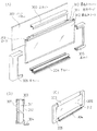
このため、従来の筐体は図5に示すように構成されていた。
図5において、51,52,53は溶接によってほぼコ字形に連結、形成された鉄パイプであり、その内側に枠体54が固着されて背面フレーム55が形成されている。56は、背面フレーム55の裏面に取り付けられる背面板である。
【0004】
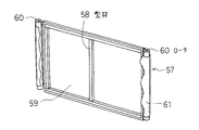
また、書込みユニット57は、図6に示すごとく金属製の型材58を裏面に取り付けたハードボード59を用い、その両側に配置したローラ60の回転により書込みシート61を移動させるように形成されている。
なお、図5において、62はほぼコ字形の表面フレーム、63は操作部、64は下部フレームである。
【0005】
従来では、上述した背面フレーム55の構造により筐体の剛性を高め、光学的安定性を確保すると共に、ハードボード59の使用によって書込み面の強度や平坦性を確保していた。
【0006】
【発明が解決しようとする課題】
しかるに、このような筐体構造では鉄等の金属部品を多く使うため重くなり、製造上、輸送上の難点があった。また、使用時に移動、携帯する際も不便が多く、壁に掛けて使うことも場合によっては不可能であった。
一方、射出成形により筐体を樹脂化して軽量にすることも考えられるが、一般に強度が不足し、また、書込み面の平坦性が得にくいと共に、金型が高価になって製造コストが増加する等の問題がある。
【0007】
そこで本発明は、筐体の主要部を樹脂のブロー成形によって形成し、筐体の軽量化、強度の向上並びに製造コスト、輸送コストの低減を図り、更に書込み面の平坦性を高めた電子黒板を提供しようとするものである。
【0008】
【解決を解決するための手段】
上記課題を解決するため、請求項1記載の発明は、書込みユニットを表裏から挟むように表面枠ユニット及び裏面枠ユニットが取り付けられ、かつ表面枠ユニット側に書込みユニットの書込み面が露出される電子黒板において、前記表面枠ユニット及び裏面枠ユニットの少なくとも一方は、樹脂のブロー成形により、書込みユニットを収納する窓部の周囲に、中空の周辺部がほぼ四角の枠状に形成されたものである。
すなわち本発明では、表面枠ユニットまたは裏面枠ユニットの何れか一方、もしくはその双方をブロー成形により形成する。
【0009】
請求項2記載の発明は、情報の書込み面が一体化された書込みボードにより書込みユニットが構成される電子黒板において、前記書込みボードは樹脂のブロー成形により中空に形成され、この書込みボードの側面に上カバー、下カバー、左カバーおよび右カバーが取付けられて書込みユニットが構成されたものである。
ここで、書込み面は、書込みボードを適宜表面処理して形成するか、書込みボードの表面にシート等を貼って形成される。
【0010】
請求項3記載の発明は、移動可能な書込みシートの表面により情報の書込み面が形成され、この書込みシートを支持ボードの表面に張り渡して書込みユニットが構成される電子黒板において、前記支持ボードは樹脂のブロー成形により中空に形成され、この支持ボードの側面に上カバー、下カバー、左カバーおよび右カバーが取付けられて書込みユニットが構成されたものである。
つまり本発明では、書込みシートを移動可能とした電子黒板において、書込みシートの背後にある支持ボードをブロー成形により形成する。
【0011】
【発明の実施の形態】
以下、図に沿って本発明の実施形態を説明する。図1、図2は請求項1に記載した発明の実施形態を示すもので、この実施形態は、図1の表面枠ユニット100と図2の裏面枠ユニット200とを組み合わせて筐体を形成するものである。
【0012】
図1(A)において、表面枠ユニット100は、矩形の窓部101とその周囲の中空の周辺部102とからなり、全体がほぼ四角形の枠状に形成されている。なお、図1(B)は図1(A)のA−A断面図である。
この表面枠ユニット100は、金型内の樹脂に空気を注入して成形するブロー成形によって形成されており、中央の窓部101は、図5に示したような書込みユニット57を収納するためのものである。
【0013】
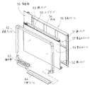
図2に示す裏面枠ユニット200も、書込みユニット57を収納する窓部201と、その周囲の中空の周辺部202とを有しており、表面枠ユニット100と同様にブロー成形にてほぼ四角形の枠状に形成されている。
組立に当たっては、書込みユニット57を表面枠ユニット100及び裏面枠ユニット200によって表裏から挟み込み、両ユニット100,200をねじ止めして全体を一体構造とする。
これにより、書込みユニット57の書込みシート61の表面(書込み面)が表面枠ユニット100側に露出する。
【0014】
この実施形態によれば、前記周辺部102,202が中空になっているので、表面枠ユニット100、裏面枠ユニット200の軽量化を図りつつ一定の強度を持たせることができる。
また、ブロー成形を用いることによって各ユニット100,200の平坦性が確保され、これらを一体化した際に歪みや隙間を生じることなく、堅牢で寸法精度の高い筐体を提供することができる。従って、電子黒板の光学系を支持する筐体として、安定した構造が得られるものである。
更に、ブロー成形では、射出成形等に比べて成形時の圧力が少なくて済み、成形機や金型が安価になるため、筐体の製造コストを大幅に低減することができる。
【0015】
次に、図3は請求項2に記載した発明の実施形態を示しており、(A)は分解斜視図、(B)は組み立てた状態の縦断面図、(C)は斜視図である。
この実施形態では、書込みユニット300としてブロー成形により中空の書込みボード301を形成し、その表面を書込み消去可能なように表面処理するか、あるいはこの書込みボード301の表面にシート状または板状の部材を貼って書込み部302が形成される。いずれにしても、この実施形態では情報の書込み面が書込みボード301に一体化されている。
【0016】
また、書込みボード301の周囲には押し出し成形等により形成した上カバー303、下カバー304、左カバー305、右カバー306が取り付けられ、背面にパーティクルボード等のバックパネル307が取り付けられて全体が構成される。
【0017】
更に、図4は請求項3に記載した発明の実施形態を示しており、(A)は分解斜視図、(B)は組み立てた状態の縦断面図、(C)は斜視図である。この実施形態は、書込みユニット310の構造以外は図3と同一である。
図4における書込みユニット310は、図3における書込みボード301と同一構造の支持ボード311をブロー成形により作り、その両側に配置したローラ313の回転によって書込みシート312を移動させるように形成されている。
【0018】
これらの図3、図4の実施形態によれば、書込みユニット300(書込みボード301)自体、または書込みユニット310の支持構造体としての支持ボード311がブロー成形によって形成されているため、書込み面の平坦性が得やすく、使い勝手の良い電子黒板を得ることができる。
同時に、電子黒板として体積上、大きなウェイトを占める書込みユニット300,310の主要部が中空であるので、電子黒板の一層の軽量化が可能である。
【0019】
【発明の効果】
以上のように請求項1記載の発明によれば、書込みユニットを包囲する枠状の筐体を樹脂のブロー成形により形成するため、鉄等の金属を主要材料とするものに比べて電子黒板の大幅な軽量化が可能になる。従って、製造時、輸送時の労力が軽減され、使用時の携帯性も向上すると共に、壁掛け式の軽量な電子黒板も容易に実現可能である。
【0020】
また、金属製の筐体に比べて遜色のない強度、剛性が得られ、光学的にも安定した構造を得ることができる。
更に、製造コスト、輸送コストの低減が可能になる。
【0021】
請求項2または3記載の発明によれば、書込み時の力が直接加わる書込みボードまたは支持ボードの平坦性を高めることができ、使い勝手の良い電子黒板を提供することができる。
【図面の簡単な説明】
【図1】請求項1に記載した発明の実施形態における表面枠ユニットの説明図である。
【図2】請求項1に記載した発明の実施形態における裏面枠ユニットの説明図である。
【図3】請求項2に記載した発明の実施形態を示す図である。
【図4】請求項3に記載した発明の実施形態を示す図である。
【図5】従来技術における筐体の分解斜視図である。
【図6】従来技術における書込みユニットの斜視図である。
【符号の説明】
100 表面枠ユニット
101,201 窓部
102,202 周辺部
200 裏面枠ユニット
300,310 書込みユニット
301 書込みボード
302 書込み部
303 上カバー
304 下カバー
305 左カバー
306 右カバー
307 バックパネル
311 支持ボード
312 書込みシート
313 ローラ[0001]
BACKGROUND OF THE INVENTION
The present invention relates to an electronic blackboard having an improved case structure, and more particularly, to an electronic blackboard that can reduce the weight of the case, improve optical stability, improve the flatness of a writing surface, and the like.
[0002]
[Prior art]
The electronic blackboard is required to have strength and flatness on the writing surface from the viewpoint of ease of writing. Further, since the electronic blackboard has an optical system such as a light source and an image sensor, an optically stable housing structure is required.
[0003]
For this reason, the conventional housing | casing was comprised as shown in FIG.
In FIG. 5, 51, 52, and 53 are iron pipes connected and formed in a substantially U shape by welding, and a frame body 54 is fixed to the inside to form a back frame 55. Reference numeral 56 denotes a back plate attached to the back surface of the back frame 55.
[0004]
Further, the
In FIG. 5,
[0005]
Conventionally, the structure of the back frame 55 described above increases the rigidity of the housing to ensure optical stability, and the use of the
[0006]
[Problems to be solved by the invention]
However, such a housing structure is heavy because many metal parts such as iron are used, and there are difficulties in manufacturing and transportation. Also, there are many inconveniences when moving and carrying when using, and it is impossible to hang it on the wall in some cases.
On the other hand, it is conceivable to make the casing light by injection molding, but generally the strength is insufficient, the flatness of the writing surface is difficult to obtain, the mold becomes expensive and the manufacturing cost increases. There are problems such as.
[0007]
Therefore, the present invention provides an electronic blackboard in which the main part of the casing is formed by blow molding of the resin to reduce the casing weight, improve the strength, reduce the manufacturing cost and the transportation cost, and further improve the flatness of the writing surface. Is to provide.
[0008]
[Means for solving the problem]
In order to solve the above problems, the invention according to claim 1 is an electronic device in which the front frame unit and the back frame unit are attached so as to sandwich the write unit from the front and back sides, and the write surface of the write unit is exposed on the front frame unit side. In the blackboard, at least one of the front surface frame unit and the back surface frame unit has a hollow peripheral portion formed in a substantially square frame shape around the window portion for storing the writing unit by blow molding of resin. .
That is, in the present invention, either the front surface frame unit or the back surface frame unit or both of them are formed by blow molding.
[0009]
According to a second aspect of the present invention, in the electronic blackboard in which a writing unit is constituted by a writing board in which an information writing surface is integrated, the writing board is formed hollow by resin blow molding , and is formed on a side surface of the writing board. The writing unit is configured by attaching an upper cover, a lower cover, a left cover, and a right cover .
Here, the writing surface is formed by appropriately surface-treating the writing board, or is formed by sticking a sheet or the like on the surface of the writing board.
[0010]
According to a third aspect of the invention, is formed the writing surface of the information by the surface of the movable writing sheet, the writing unit stretched the writing sheet to the surface of the support board is configured electronic blackboard, the support board The writing unit is formed by forming a hollow by resin blow molding and attaching an upper cover, a lower cover, a left cover, and a right cover to the side surface of the support board .
That is, in the present invention, in the electronic blackboard in which the writing sheet is movable, the support board behind the writing sheet is formed by blow molding.
[0011]
DETAILED DESCRIPTION OF THE INVENTION
Hereinafter, embodiments of the present invention will be described with reference to the drawings. 1 and 2 show an embodiment of the invention described in claim 1, and this embodiment forms a casing by combining the front
[0012]
In FIG. 1A, the
The
[0013]
The back
In assembling, the
Thereby, the surface (writing surface) of the
[0014]
According to this embodiment, since the
Moreover, the flatness of each
Furthermore, blow molding requires less pressure at the time of molding than injection molding and the like, and the molding machine and mold are inexpensive, so the manufacturing cost of the housing can be greatly reduced.
[0015]
Next, FIG. 3 shows an embodiment of the invention described in claim 2, wherein (A) is an exploded perspective view, (B) is a longitudinal sectional view in an assembled state, and (C) is a perspective view.
In this embodiment, a
[0016]
Further, an
[0017]
FIG. 4 shows an embodiment of the invention described in claim 3, wherein (A) is an exploded perspective view, (B) is a longitudinal sectional view in an assembled state, and (C) is a perspective view. This embodiment is the same as FIG. 3 except for the structure of the writing unit 310.
The writing unit 310 in FIG. 4 is formed such that a
[0018]
According to the embodiments of FIGS. 3 and 4, the writing unit 300 (writing board 301) itself or the
At the same time, since the main part of the writing
[0019]
【The invention's effect】
As described above, according to the first aspect of the present invention, since the frame-shaped casing surrounding the writing unit is formed by resin blow molding, the electronic blackboard is more in comparison with the one made mainly of metal such as iron. Significant weight reduction is possible. Therefore, labor during manufacture and transportation is reduced, portability during use is improved, and a wall-mounted lightweight electronic blackboard can be easily realized.
[0020]
Further, strength and rigidity comparable to those of a metal casing can be obtained, and an optically stable structure can be obtained.
Furthermore, it is possible to reduce manufacturing costs and transportation costs.
[0021]
According to the second or third aspect of the invention, the flatness of the writing board or the supporting board to which a force at the time of writing is directly applied can be improved, and an electronic blackboard that is easy to use can be provided.
[Brief description of the drawings]
FIG. 1 is an explanatory view of a surface frame unit in an embodiment of the invention described in claim 1;
FIG. 2 is an explanatory view of a back frame unit according to the embodiment of the present invention.
FIG. 3 is a view showing an embodiment of the invention described in claim 2;
FIG. 4 is a diagram showing an embodiment of the invention as set forth in claim 3;
FIG. 5 is an exploded perspective view of a housing in the prior art.
FIG. 6 is a perspective view of a writing unit in the prior art.
[Explanation of symbols]
100
Claims (3)
前記表面枠ユニット及び裏面枠ユニットの少なくとも一方は、樹脂のブロー成形により、書込みユニットを収納する窓部の周囲に、中空の周辺部がほぼ四角の枠状に形成されたことを特徴とする電子黒板。In the electronic blackboard in which the front frame unit and the rear frame unit are attached so as to sandwich the writing unit from the front and back, and the writing surface of the writing unit is exposed on the front frame unit side,
At least one of the front surface frame unit and the back surface frame unit has a hollow peripheral portion formed in a substantially square frame shape around the window portion for storing the writing unit by blow molding of resin. blackboard.
前記書込みボードは樹脂のブロー成形により中空に形成され、この書込みボードの側面に上カバー、下カバー、左カバーおよび右カバーが取付けられて書込みユニットが構成されたことを特徴とする電子黒板。In the electronic blackboard where the writing unit is composed of a writing board with an integrated information writing surface,
An electronic blackboard, wherein the writing board is formed hollow by resin blow molding , and a writing unit is configured by attaching an upper cover, a lower cover, a left cover, and a right cover to a side surface of the writing board .
前記支持ボードは樹脂のブロー成形により中空に形成され、この支持ボードの側面に上カバー、下カバー、左カバーおよび右カバーが取付けられて書込みユニットが構成されたことを特徴とする電子黒板。In the electronic blackboard in which a writing surface of information is formed by the surface of the movable writing sheet and the writing unit is formed by stretching the writing sheet on the surface of the support board.
An electronic blackboard, wherein the support board is formed hollow by resin blow molding , and an upper cover, a lower cover, a left cover, and a right cover are attached to a side surface of the support board to constitute a writing unit .
Priority Applications (1)
| Application Number | Priority Date | Filing Date | Title |
|---|---|---|---|
| JP24072396A JP3661815B2 (en) | 1996-09-11 | 1996-09-11 | Electronic blackboard |
Applications Claiming Priority (1)
| Application Number | Priority Date | Filing Date | Title |
|---|---|---|---|
| JP24072396A JP3661815B2 (en) | 1996-09-11 | 1996-09-11 | Electronic blackboard |
Publications (2)
| Publication Number | Publication Date |
|---|---|
| JPH1093748A JPH1093748A (en) | 1998-04-10 |
| JP3661815B2 true JP3661815B2 (en) | 2005-06-22 |
Family
ID=17063752
Family Applications (1)
| Application Number | Title | Priority Date | Filing Date |
|---|---|---|---|
| JP24072396A Expired - Fee Related JP3661815B2 (en) | 1996-09-11 | 1996-09-11 | Electronic blackboard |
Country Status (1)
| Country | Link |
|---|---|
| JP (1) | JP3661815B2 (en) |
Families Citing this family (3)
| Publication number | Priority date | Publication date | Assignee | Title |
|---|---|---|---|---|
| JP3667251B2 (en) | 2000-05-30 | 2005-07-06 | キヤノン・コンポーネンツ株式会社 | Image sensor, image processing apparatus using the same, and information processing system |
| US20110244442A1 (en) * | 2010-03-31 | 2011-10-06 | Vaddio, Llc | Video whiteboard apparatus and method |
| KR101007248B1 (en) * | 2010-09-10 | 2011-01-10 | 김철곤 | Multi-color copyboard to automatically switch between copyboard and whiteboard and to prevent screen blur |
-
1996
- 1996-09-11 JP JP24072396A patent/JP3661815B2/en not_active Expired - Fee Related
Also Published As
| Publication number | Publication date |
|---|---|
| JPH1093748A (en) | 1998-04-10 |
Similar Documents
| Publication | Publication Date | Title |
|---|---|---|
| US10917985B1 (en) | Flexible display device | |
| JPH1051713A (en) | Projection Television Display Holder | |
| DE69601731D1 (en) | PERSONNEL COMPUTER WITH SPEAKERS | |
| EP1320771B1 (en) | Means for maintaining spatial relationships in lenticular display units | |
| JP3661815B2 (en) | Electronic blackboard | |
| JP3225476B2 (en) | Projection TV screen mounting structure | |
| JP2999855B2 (en) | Electronic blackboard | |
| CN2173445Y (en) | Advertising vehicle with a combined large screen | |
| JP3257875B2 (en) | Lens sheet mounting device | |
| JPH0550432U (en) | Liquid crystal display | |
| JP2583399Y2 (en) | Display body | |
| JPH08256887A (en) | Display tool | |
| CN212990578U (en) | All-in-one is used in lecture | |
| JP3104117U (en) | 3D display sheet appreciation stand | |
| JPH0219825Y2 (en) | ||
| JP3097660U (en) | 3D display sheet appreciation stand | |
| JPH08183292A (en) | Writing board and electronic writing board | |
| JP6722978B2 (en) | Stand hanging scroll | |
| JPH0614547Y2 (en) | Electronic blackboard | |
| JP2024060174A (en) | Display Panel | |
| JPH04287499A (en) | Panel speaker | |
| JPH0470645U (en) | ||
| JPH08187992A (en) | Electronic blackboard | |
| JPH0418317U (en) | ||
| JPH1176007A (en) | Display case |
Legal Events
| Date | Code | Title | Description |
|---|---|---|---|
| A977 | Report on retrieval |
Free format text: JAPANESE INTERMEDIATE CODE: A971007 Effective date: 20041213 |
|
| A131 | Notification of reasons for refusal |
Free format text: JAPANESE INTERMEDIATE CODE: A131 Effective date: 20041228 |
|
| A521 | Written amendment |
Free format text: JAPANESE INTERMEDIATE CODE: A523 Effective date: 20050222 |
|
| TRDD | Decision of grant or rejection written | ||
| A01 | Written decision to grant a patent or to grant a registration (utility model) |
Free format text: JAPANESE INTERMEDIATE CODE: A01 Effective date: 20050316 |
|
| A61 | First payment of annual fees (during grant procedure) |
Free format text: JAPANESE INTERMEDIATE CODE: A61 Effective date: 20050316 |
|
| R150 | Certificate of patent or registration of utility model |
Free format text: JAPANESE INTERMEDIATE CODE: R150 |
|
| FPAY | Renewal fee payment (event date is renewal date of database) |
Free format text: PAYMENT UNTIL: 20080401 Year of fee payment: 3 |
|
| FPAY | Renewal fee payment (event date is renewal date of database) |
Free format text: PAYMENT UNTIL: 20090401 Year of fee payment: 4 |
|
| LAPS | Cancellation because of no payment of annual fees |