JP3661823B2 - High temperature wear resistant sintered alloy - Google Patents
High temperature wear resistant sintered alloy Download PDFInfo
- Publication number
- JP3661823B2 JP3661823B2 JP09416597A JP9416597A JP3661823B2 JP 3661823 B2 JP3661823 B2 JP 3661823B2 JP 09416597 A JP09416597 A JP 09416597A JP 9416597 A JP9416597 A JP 9416597A JP 3661823 B2 JP3661823 B2 JP 3661823B2
- Authority
- JP
- Japan
- Prior art keywords
- less
- impurities
- sintered alloy
- balance
- wear
- Prior art date
- Legal status (The legal status is an assumption and is not a legal conclusion. Google has not performed a legal analysis and makes no representation as to the accuracy of the status listed.)
- Expired - Fee Related
Links
Images




Classifications
-
- C—CHEMISTRY; METALLURGY
- C22—METALLURGY; FERROUS OR NON-FERROUS ALLOYS; TREATMENT OF ALLOYS OR NON-FERROUS METALS
- C22C—ALLOYS
- C22C33/00—Making ferrous alloys
- C22C33/02—Making ferrous alloys by powder metallurgy
- C22C33/0207—Using a mixture of prealloyed powders or a master alloy
-
- C—CHEMISTRY; METALLURGY
- C22—METALLURGY; FERROUS OR NON-FERROUS ALLOYS; TREATMENT OF ALLOYS OR NON-FERROUS METALS
- C22C—ALLOYS
- C22C38/00—Ferrous alloys, e.g. steel alloys
- C22C38/12—Ferrous alloys, e.g. steel alloys containing tungsten, tantalum, molybdenum, vanadium, or niobium
-
- C—CHEMISTRY; METALLURGY
- C22—METALLURGY; FERROUS OR NON-FERROUS ALLOYS; TREATMENT OF ALLOYS OR NON-FERROUS METALS
- C22C—ALLOYS
- C22C33/00—Making ferrous alloys
- C22C33/02—Making ferrous alloys by powder metallurgy
- C22C33/0257—Making ferrous alloys by powder metallurgy characterised by the range of the alloying elements
-
- C—CHEMISTRY; METALLURGY
- C22—METALLURGY; FERROUS OR NON-FERROUS ALLOYS; TREATMENT OF ALLOYS OR NON-FERROUS METALS
- C22C—ALLOYS
- C22C38/00—Ferrous alloys, e.g. steel alloys
- C22C38/18—Ferrous alloys, e.g. steel alloys containing chromium
- C22C38/22—Ferrous alloys, e.g. steel alloys containing chromium with molybdenum or tungsten
Landscapes
- Chemical & Material Sciences (AREA)
- Engineering & Computer Science (AREA)
- Materials Engineering (AREA)
- Mechanical Engineering (AREA)
- Metallurgy (AREA)
- Organic Chemistry (AREA)
- Powder Metallurgy (AREA)
Description
【0001】
【発明の属する技術分野】
本発明は、例えば、内燃機関に使用されるバルブシート等の高温での耐摩耗性に優れていることが要求される部品の素材として好適に利用される高温耐摩耗性鉄系焼結合金に関するものである。
【0002】
【従来の技術】
従来の耐摩耗材としては、特公平5−55593号公報や特開平7−233454号公報などで開示された高Co系の材料や、特開平5−9667号公報、特公平1−51539号公報などで開示された耐摩耗性を向上させるためにW,Mo,V,Nb,Ti,Ta等の微細炭化物を基地中に分散させた材料をはじめ、その他多くの材料が知られている。
【0003】
【発明が解決しようとする課題】
しかし、近年の内燃機関の高性能化、バルブシートにおける高温耐摩耗性、有・無鉛ガソリン対応に伴う耐食性向上および被削性向上の要求がさらに高まる状況下において、上記従来材である高Co系の材料では経済的に不利であり、また、微細炭化物が基地中に分散した材料では炭化物の種類および炭化物の量が最適であるとは言えず、自己耐摩耗性と相手耐攻撃性の両立が困難であり、要求性能を十分満足することが出来ないという問題点があったことから、このような問題点を解決することが課題としてあった。
【0004】
【発明の目的】
本発明は、このような従来の問題点に着目してなされたものであって、自己の耐摩耗性を良好なものにすることが可能であると共に相手材に対する攻撃性を小さなものとすることが可能であり、自己耐摩耗性と相手耐攻撃性の両立が可能となって、要求性能を十分に満足する高温耐摩耗性焼結合金を提供することを目的としている。
【0005】
【課題を解決するための手段】
本発明に係わる一実施形態の高温耐摩耗性焼結合金は、請求項1に記載しているように、全体組成が、重量比で、W:3〜13.4%、V:0.4〜5.6%、Cr:0.2〜5.6%、Si:0.1〜0.6%、Mn:0.1〜0.6%、C:0.6〜2.2%、残部Feおよび不純物からなる成分を有し、且つ、W:3〜7%、Cr:1%以下、Si:0.1〜0.6%、Mn:0.1〜0.6%、C:2.2%以下、残部Feおよび不純物からなる第1基材相に対し、W:3〜15%、V:2〜7%、Cr:1〜7%、Si:0.1〜0.6%、Mn:0.1〜0.6%、C:2.2%以下、残部Feおよび不純物からなる第2基材相が20〜80wt%を占めており、これら2つの相が斑状に分布する組織を呈するものとしたことを特徴としている。
【0006】
また、本発明に係わる他の実施形態の高温耐摩耗性焼結合金は、請求項2に記載しているように、全体組成が、重量比で、W:3〜13.4%、V:0.8〜5.9%、Cr:0.2〜5.6%、Si:0.1〜0.6%、Mn:0.1〜0.6%、C:0.6〜2.2%、残部Feおよび不純物からなる成分を有し、且つ、W:3〜7%、V:0.5〜1.5%、Cr:1%以下、Si:0.1〜0.6%、Mn:0.1〜0.6%、C:2.2%以下、残部Feおよび不純物からなる第1基材相に対し、W:3〜15%、V:2〜7%、Cr:1〜7%、Si:0.1〜0.6%、Mn:0.1〜0.6%、C:2.2%以下、残部Feおよび不純物からなる第2基材相が20〜80wt%を占めており、これら2つの相が斑状に分布する組織を呈するものとしたことを特徴としている。
【0007】
さらに、本発明に係わるさらに他の実施形態の高温耐摩耗性焼結合金は、請求項3に記載しているように、全体組成が、重量比で、W:3〜13.4%、V:0.4〜5.6%、Cr:0.2〜5.6%、Si:0.1〜0.6%、Mn:0.2〜1.0%、S:0.1〜0.6%、C:0.6〜2.2%、残部Feおよび不純物からなる成分を有し、且つ、W:3〜7%、Cr:1%以下、Si:0.1〜0.6%、Mn:0.2〜1.0%、S:0.1〜0.6%、C:2.2%以下、残部Feおよび不純物からなる第1基材相に対し、W:3〜15%、V:2〜7%、Cr:1〜7%、Si:0.1〜0.6%、Mn:0.2〜1.0%、S:0.1〜0.6%、C:2.2%以下、残部Feおよび不純物からなる第2基材相が20〜80wt%を占めており、これら2つの相が斑状に分布する組織を呈するものとしたことを特徴としている。
【0008】
さらにまた、本発明に係わるさらに他の実施形態の高温耐摩耗性焼結合金は、請求項4に記載しているように、全体組成が、重量比で、W:3〜13.4%、V:0.8〜5.9%、Cr:0.2〜5.6%、Si:0.1〜0.6%、Mn:0.2〜1.0%、S:0.1〜0.6%、C:0.6〜2.2%、残部Feおよび不純物からなる成分を有し、且つ、W:3〜7%、V:0.5〜1.5%、Cr:1%以下、Si:0.1〜0.6%、Mn:0.2〜1.0%、S:0.1〜0.6%、C:2.2%以下、残部Feおよび不純物からなる第1基材相に対し、W:3〜15%、V:2〜7%、Cr:1〜7%、Si:0.1〜0.6%、Mn:0.2〜1.0%、S:0.1〜0.6%、C:2.2%以下、残部Feおよび不純物からなる第2基材相が20〜80wt%を占めており、これら2つの相が斑状に分布する組織を呈するものとしたことを特徴としている。
【0009】
さらにまた、本発明に係わるさらに他の実施形態の高温耐摩耗性焼結合金は、請求項5に記載しているように、全体組成が、重量比で、W:3〜13.4%、V:0.4〜5.6%、Cr:0.2〜5.6%、Si:0.6〜5.0%、Mn:0.1〜0.6%、C:0.6〜2.2%、残部Feおよび不純物からなる成分を有し、且つ、W:3〜7%、Cr:1%以下、Si:0.6〜5.0%、Mn:0.1〜0.6%、C:2.2%以下、残部Feおよび不純物からなる第1基材相に対し、W:3〜15%、V:2〜7%、Cr:1〜7%、Si:0.6〜5.0%、Mn:0.1〜0.6%、C:2.2%以下、残部Feおよび不純物からなる第2基材相が20〜80wt%を占めており、これら2つの相が斑状に分布する組織を呈するものとしたことを特徴としている。
【0010】
さらにまた、本発明に係わるさらに他の実施形態の高温耐摩耗性焼結合金は、請求項6に記載しているように、全体組成が、重量比で、W:3〜13.4%、V:0.8〜5.9%、Cr:0.2〜5.6%、Si:0.6〜5.0%、Mn:0.1〜0.6%、C:0.6〜2.2%、残部Feおよび不純物からなる成分を有し、且つ、W:3〜7%、V:0.5〜1.5%、Cr:1%以下、Si:0.6〜5.0%、Mn:0.1〜0.6%、C:2.2%以下、残部Feおよび不純物からなる第1基材相に対し、W:3〜15%、V:2〜7%、Cr:1〜7%、Si:0.6〜5.0%、Mn:0.1〜0.6%、C:2.2%以下、残部Feおよび不純物からなる第2基材相が20〜80wt%を占めており、これら2つの相が斑状に分布する組織を呈するものとしたことを特徴としている。
【0011】
さらにまた、本発明に係わるさらに他の実施形態の高温耐摩耗性焼結合金は、請求項7に記載しているように、全体組成が、重量比で、W:3〜13.4%、V:0.4〜5.6%、Cr:0.2〜5.6%、Si:0.6〜5.0%、Mn:0.2〜1.0%、S:0.1〜0.6%、C:0.6〜2.2%、残部Feおよび不純物からなる成分を有し、且つ、W:3〜7%、Cr:1%以下、Si:0.6〜5.0%、Mn:0.2〜1.0%、S:0.1〜0.6%、C:2.2%以下、残部Feおよび不純物からなる第1基材相に対し、W:3〜15%、V:2〜7%、Cr:1〜7%、Si:0.6〜5.0%、Mn:0.2〜1.0%、S:0.1〜0.6%、C:2.2%以下、残部Feおよび不純物からなる第2基材相が20〜80wt%を占めており、これら2つの相が斑状に分布する組織を呈するものとしたことを特徴としている。
【0012】
さらにまた、本発明に係わるさらに他の実施形態の高温耐摩耗性焼結合金は、請求項8に記載しているように、全体組成が、重量比で、W:3〜13.4%、V:0.8〜5.9%、Cr:0.2〜5.6%、Si:0.6〜5.0%、Mn:0.2〜1.0%、S:0.1〜0.6%、C:0.6〜2.2%、残部Feおよび不純物からなる成分を有し、且つ、W:3〜7%、V:0.5〜1.5%、Cr:1%以下、Si:0.6〜5.0%、Mn:0.2〜1.0%、S:0.1〜0.6%、C:2.2%以下、残部Feおよび不純物からなる第1基材相に対し、W:3〜15%、V:2〜7%、Cr:1〜7%、Si:0.6〜5.0%、Mn:0.2〜1.0%、S:0.1〜0.6%、C:2.2%以下、残部Feおよび不純物からなる第2基材相が20〜80wt%を占めており、これら2つの相が斑状に分布する組織を呈するものとしたことを特徴としている。
【0013】
さらにまた、本発明に係わるさらに他の実施形態の高温耐摩耗性焼結合金は、請求項9に記載しているように、請求項1,2,5,6のいずれかに記載の焼結合金がさらにMnSを含有し、このMnSが粒界に0.3〜1.6wt%分散してなるものとしたことを特徴とし、さらに請求項10に記載しているように、請求項1,2,5,6のいずれかに記載の焼結合金の気孔内にMnSが0.3〜1.6wt%分散してなるものとしたことを特徴としている。
【0014】
さらにまた、本発明に係わるさらに他の実施形態の高温耐摩耗性焼結合金は、請求項11に記載しているように、請求項1,2,3,4,5,6,7,8,9,10のいずれかに記載の焼結合金の気孔内にCuないしはCu合金を溶浸してなるものとしたことを特徴としている。
【0015】
さらにまた、本発明のさらに他の実施形態の高温耐摩耗性焼結合金は、請求項12に記載しているように、請求項1,2,3,4,5,6,7,8,9,10のいずれかに記載の焼結合金の気孔内にPbないしはPb合金を溶浸してなるものとしたことを特徴としている。
【0016】
さらにまた、本発明のさらに他の実施形態の高温耐摩耗性焼結合金は、請求項13に記載しているように、請求項1,2,3,4,5,6,7,8,9,10のいずれかに記載の焼結合金の気孔内にアクリル系樹脂を含浸してなるものとしたことを特徴としている。
【0017】
【発明の効果】
本発明による高温耐摩耗性焼結合金では、請求項1に記載しているように、全体組成が、重量比で、W:3〜13.4%、V:0.4〜5.6%、Cr:0.2〜5.6%、Si:0.1〜0.6%、Mn:0.1〜0.6%、C:0.6〜2.2%、残部Feおよび不純物からなる成分を有し、且つ、W:3〜7%、Cr:1%以下、Si:0.1〜0.6%、Mn:0.1〜0.6%、C:2.2%以下、残部Feおよび不純物からなる第1基材相に対し、W:3〜15%、V:2〜7%、Cr:1〜7%、Si:0.1〜0.6%、Mn:0.1〜0.6%、C:2.2%以下、残部Feおよび不純物からなる第2基材相が20〜80wt%を占めており、これら2つの相が斑状に分布する組織を呈するものとしたから、自己の耐摩耗性を良好なものとすることが可能であると共に相手材に対する攻撃性を小さなものとすることが可能であるので、自己耐摩耗性と相手耐攻撃性の両立が可能となり、高温耐摩耗性焼結合金としての要求性能を十分満足することができるものであるという著しく優れた効果がもたらされる。
【0018】
そして、請求項5,6,7,8に記載しているように、第1基材相および第2基材相中のSiを0.6〜5.0%に増加させたり、請求項2,4,6,8に記載しているように、第2基材相中にVを0.5〜1.5%含有させたりすることによって、有鉛ガソリン使用の環境下においても耐摩耗性がより一層向上したものにすることが可能であるという著しく優れた効果がもたらされる。
【0019】
さらに、請求項3,4,7,8に記載しているように、基地中のMnを0.2〜1.0%に増量すると共にSを0.1〜0.6%加えることによって基地中にMnSが析出することとなるので、被削性を大幅に改善することができるという著しく優れた効果がもたらされる。
【0020】
さらにまた、請求項9に記載しているように、焼結合金の粒界または気孔内にMnSを0.3〜1.6wt%分散させることによって、基地中にMnSが析出した場合と同様に被削性を大幅に改善することができるという著しく優れた効果がもたらされる。
【0021】
そのうえ、請求項10に記載しているように、焼結合金の気孔内にCuないしはCu合金を溶浸させたり、請求項11に記載しているように、焼結合金の気孔内にPbないしはPb合金を溶浸させたりすることによって、さらに優れた耐摩耗性を有するものにすることが可能であるという著しく優れた効果がもたらされる。また、請求項11に記載しているように、焼結合金の気孔内にPbないしはPb合金を溶浸させたり、請求項12に記載しているように、焼結合金の気孔内にアクリル系樹脂を含浸させたりすることによって、被削性のより一層の向上を得ることが可能であるという著しく優れた効果がもたらされる。
【0022】
したがって、本発明による高温耐摩耗性焼結合金では、従来の高Co系の材料に対し、経済性と耐摩耗性の両面において大きな改善を成し得るという顕著な効果がもたらされる。
【0023】
【発明の作用】
請求項1に記載の第1発明として、全体組成が、重量比で、W:3〜13.4%、V:0.4〜5.6%、Cr:0.2〜5.6%、Si:0.1〜0.6%、Mn:0.1〜0.6%、C:0.6〜2.2%、残部Feおよび不純物からなる成分を有し、且つ、W:3〜7%、Cr:1%以下、Si:0.1〜0.6%、Mn:0.1〜0.6%、C:2.2%以下、残部Feおよび不純物からなる第1基材相に対し、W:3〜15%、V:2〜7%、Cr:1〜7%、Si:0.1〜0.6%、Mn:0.1〜0.6%、C:2.2%以下、残部Feおよび不純物からなる第2基材相が20〜80wt%を占めており、これら2つの相がより望ましくは平均粒径20〜150μmの大きさで斑状に分布する組織を呈する高温耐摩耗性焼結合金であるものとしていて、この高温耐摩耗性焼結合金では、WのM6C型炭化物が分散した第1基材相と、WのM6C型炭化物とVのMC型炭化物が均一に分散しかつまたCrで基材を強化した第2基材相がより望ましくは平均粒径20〜150μmの大きさで斑状に分布する組織構成にすることで、バルブシートの耐摩耗性を低下させることなく、相手材であるバルブへの攻撃性を減少させることが可能となった。
【0024】
本発明の高温耐摩耗性焼結合金を構成する第1基材相においては、Wの含有量が7%を上回るとバルブへの攻撃性が高まり、3%を下回るとバルブシートの耐摩耗性が低下する。また、Crはバルブへの攻撃性が高まるため無くても良いが、焼結時に第2基材相からの拡散により1%以下存在していても良い。
【0025】
また、第2基材相も同様にW、Vの含有量がそれぞれ15%、7%を上回るとバルブへの攻撃性が高まり、それぞれ3%、2%を下回るとバルブシートの耐摩耗性が低下する。さらに、第2基材相にCrを1〜7%含有させることで焼入性が向上し、さらに硬いMC型のV炭化物が析出することとなるため、第1基材相よりも硬くなることで硬さが斑状になり良好な耐摩耗性が得られる。そして、Crの含有量が7%を上回るとバルブへの攻撃性が高まり、1%を下回るとバルブシートの耐摩耗性が低下する。
【0026】
Siは脱酸剤として有効であり素地に含有しているが、Siの含有量が0.6%を上回ると強度が低下し、0.1%を下回っても焼結性が阻害されて強度が低下する。
【0027】
Mnは0.1%以上で高い強度が得られるが、0.6%を上回ると焼結性が阻害されて強度が低下する。
【0028】
さらに、第1基材相と第2基材相の割合は、第1基材相に対して硬い第2基材材が20%を下回るとバルブシートの耐摩耗性が低下し、80%を上回るとバルブへの攻撃性が高まる。
【0029】
請求項2に記載の第2発明として、全体組成が、重量比で、W:3〜13.4%、V:0.8〜5.9%、Cr:0.2〜5.6%、Si:0.1〜0.6%、Mn:0.1〜0.6%、C:0.6〜2.2%、残部Feおよび不純物からなる成分を有し、且つ、W:3〜7%、V:0.5〜1.5%、Cr:1%以下、Si:0.1〜0.6%、Mn:0.1〜0.6%、C:2.2%以下、残部Feおよび不純物からなる第1基材相に対し、W:3〜15%、V:2〜7%、Cr:1〜7%、Si:0.1〜0.6%、Mn:0.1〜0.6%、C:2.2%以下、残部Feおよび不純物からなる第2基材相が20〜80wt%を占めており、これら2つの相がより望ましくは平均粒径20〜150μmの大きさで斑状に分布する組織を呈する高温耐摩耗性焼結合金であるものとしていて、この高温耐摩耗性焼結合金では第1発明の第1基材相にVを0.5〜1.5%含有させることで耐食性をより一層向上させ、有鉛ガソリン使用の環境下において良好な耐摩耗性が得られるものとしている。このとき、V含有量が0.5%を下回ると耐食性が不足するため耐摩耗性が低下し、1.5%を上回るとバルブへの攻撃性が高まる。
【0030】
請求項3に記載の第3発明として、全体組成が、重量比で、W:3〜13.4%、V:0.4〜5.6%、Cr:0.2〜5.6%、Si:0.1〜0.6%、Mn:0.2〜1.0%、S:0.1〜0.6%、C:0.6〜2.2%、残部Feおよび不純物からなる成分を有し、且つ、W:3〜7%、Cr:1%以下、Si:0.1〜0.6%、Mn:0.2〜1.0%、S:0.1〜0.6%、C:2.2%以下、残部Feおよび不純物からなる第1基材相に対し、W:3〜15%、V:2〜7%、Cr:1〜7%、Si:0.1〜0.6%、Mn:0.2〜1.0%、S:0.1〜0.6%、C:2.2%以下、残部Feおよび不純物からなる第2基材相が20〜80wt%を占めており、これら2つの相がより望ましくは平均粒径20〜150μmの大きさで斑状に分布する組織を呈するものとしていて、高温耐摩耗性焼結合金では、第1発明の基材にMnSを析出させることで良好な被削性が得られるようにしている。このとき、Mnの含有量が1.0%を上回り、Sの含有量が0.6%を上回ると粉末の圧縮性が低下することによって強度が低下し、Mnの含有量が0.2%を下回り、Sの含有量が0.1%を下回るとMnSを必要量析出させることができなくなって被削性向上の作用が小さいものとなる。
【0031】
請求項4に記載の第4発明として、全体組成が、重量比で、W:3〜13.4%、V:0.8〜5.9%、Cr:0.2〜5.6%、Si:0.1〜0.6%、Mn:0.2〜1.0%、S:0.1〜0.6%、C:0.6〜2.2%、残部Feおよび不純物からなる成分を有し、且つ、W:3〜7%、V:0.5〜1.5%、Cr:1%以下、Si:0.1〜0.6%、Mn:0.2〜1.0%、S:0.1〜0.6%、C:2.2%以下、残部Feおよび不純物からなる第1基材相に対し、W:3〜15%、V:2〜7%、Cr:1〜7%、Si:0.1〜0.6%、Mn:0.2〜1.0%、S:0.1〜0.6%、C:2.2%以下、残部Feおよび不純物からなる第2基材相が20〜80wt%を占めており、これら2つの相がより望ましくは平均粒径20〜150μmの大きさで斑状に分布する組織を呈する高温耐摩耗性焼結合金であるものとしていて、この高温耐摩耗性焼結合金では、第2発明の基材にMnSを析出させることで良好な被削性が得られるようにしている。このとき、Mnの含有量が1.0%を上回り、Sの含有量が0.6%を上回ると粉末の圧縮性が低下することによって強度が低下し、Mnの含有量が0.2%を下回り、Sの含有量が0.1%を下回るとMnSを必要量析出させることができなくなって被削性向上の作用が小さいものとなる。
【0032】
請求項5に記載の第5発明として、全体組成が、重量比で、W:3〜13.4%、V:0.4〜5.6%、Cr:0.2〜5.6%、Si:0.6〜5.0%、Mn:0.1〜0.6%、C:0.6〜2.2%、残部Feおよび不純物からなる成分を有し、且つ、W:3〜7%、Cr:1%以下、Si:0.6〜5.0%、Mn:0.1〜0.6%、C:2.2%以下、残部Feおよび不純物からなる第1基材相に対し、W:3〜15%、V:2〜7%、Cr:1〜7%、Si:0.6〜5.0%、Mn:0.1〜0.6%、C:2.2%以下、残部Feおよび不純物からなる第2基材相が20〜80wt%を占めており、これら2つの相がより望ましくは平均粒径20〜150μmの大きさで斑状に分布する組織を呈する高温耐摩耗性焼結合金であるものとしていて、この高温耐摩耗性焼結合金では、第1発明のSi含有量を0.6〜5.0%に増加することで第1発明材よりも強度および粉末の圧縮性は低下するものの、耐食性がより一層向上したものとなり、有鉛ガソリン使用の環境下において良好な耐摩耗性が得られるものとなる。このとき、Siの含有量が5.0%を超えると、強度が低下すると共に粉末の圧縮性が著しく低下し、Siの含有量が0.6%を下回ると耐食性向上の作用が小さいものとなる。
【0033】
請求項6に記載の第6発明として、全体組成が、重量比で、W:3〜13.4%、V:0.8〜5.9%、Cr:0.2〜5.6%、Si:0.6〜5.0%、Mn:0.1〜0.6%、C:0.6〜2.2%、残部Feおよび不純物からなる成分を有し、且つ、W:3〜7%、V:0.5〜1.5%、Cr:1%以下、Si:0.6〜5.0%、Mn:0.1〜0.6%、C:2.2%以下、残部Feおよび不純物からなる第1基材相に対し、W:3〜15%、V:2〜7%、Cr:1〜7%、Si:0.6〜5.0%、Mn:0.1〜0.6%、C:2.2%以下、残部Feおよび不純物からなる第2基材相が20〜80wt%を占めており、これら2つの相がより望ましくは平均粒径20〜150μmの大きさで斑状に分布する組織を呈する高温耐摩耗性焼結合金であるものとしていて、この高温耐摩耗性焼結合金では、第2発明のSi含有量を0.6〜5.0%に増加することで第2発明材よりも強度および粉末の圧縮性は低下するものの、耐食性がより一層向上したものとなり、有鉛ガソリン使用の環境下において良好な耐摩耗性が得られるものとなる。このとき、Siの含有量が5.0%を超えると、強度が低下すると共に粉末の圧縮性が著しく低下し、Siの含有量が0.6%を下回ると耐食性向上の作用が小さいものとなる。
【0034】
請求項7に記載の第7発明として、全体組成が、重量比で、W:3〜13.4%、V:0.4〜5.6%、Cr:0.2〜5.6%、Si:0.6〜5.0%、Mn:0.2〜1.0%、S:0.1〜0.6%、C:0.6〜2.2%、残部Feおよび不純物からなる成分を有し、且つ、W:3〜7%、Cr:1%以下、Si:0.6〜5.0%、Mn:0.2〜1.0%、S:0.1〜0.6%、C:2.2%以下、残部Feおよび不純物からなる第1基材相に対し、W:3〜15%、V:2〜7%、Cr:1〜7%、Si:0.6〜5.0%、Mn:0.2〜1.0%、S:0.1〜0.6%、C:2.2%以下、残部Feおよび不純物からなる第2基材相が20〜80wt%を占めており、これら2つの相がより望ましくは平均粒径20〜150μmの大きさで斑状に分布する組織を呈する高温耐摩耗性焼結合金であるものとしていて、この高温耐摩耗性焼結合金では、第1発明の基材にMnSを析出させ、Si含有量を0.6〜5.0%とすることで被削性および耐食性がさらに向上するようにしたものである。このとき、Mnの含有量が1.0%よりも多く、Sの含有量が0.6%よりも多くなってMnSが所定の量を上回ると粉末の圧縮性が低下することによって強度が低下し、Mnの含有量が0.2%よりも少なく、Sの含有量が0.1%よりも少ないと、MnSが所定の量を下回ることになって被削性向上の作用が小さいものとなる。また、Siの含有量を0.6〜5.0%に増加することで第1発明材よりも強度および粉末の圧縮性は低下するものの耐食性がより一層向上したものとなり、有鉛ガソリン使用の環境下において良好な耐摩耗性が得られるものとなる。このとき、Siの含有量が5.0%を超えると、強度が低下すると共に粉末の圧縮性も著しく低下し、Siの含有量が0.6%を下回ると耐食性向上の作用が小さいものとなる。
【0035】
請求項8に記載の第8発明として、全体組成が、重量比で、W:3〜13.4%、V:0.8〜5.9%、Cr:0.2〜5.6%、Si:0.6〜5.0%、Mn:0.2〜1.0%、S:0.1〜0.6%、C:0.6〜2.2%、残部Feおよび不純物からなる成分を有し、且つ、W:3〜7%、V:0.5〜1.5%、Cr:1%以下、Si:0.6〜5.0%、Mn:0.2〜1.0%、S:0.1〜0.6%、C:2.2%以下、残部Feおよび不純物からなる第1基材相に対し、W:3〜15%、V:2〜7%、Cr:1〜7%、Si:0.6〜5.0%、Mn:0.2〜1.0%、S:0.1〜0.6%、C:2.2%以下、残部Feおよび不純物からなる第2基材相が20〜80wt%を占めており、これら2つの相がより望ましくは平均粒径20〜150μmの大きさで斑状に分布する組織を呈する高温耐摩耗性焼結合金であるものとしていて、この高温耐摩耗性焼結合金では、第2発明の基材にMnSを析出させ、Si含有量を0.6〜5.0%とすることで被削性および耐食性がさらに向上するようにしたものである。このとき、Mnの含有量が1.0%よりも多く、Sの含有量が0.6%よりも多くなってMnSが所定の量を上回ると粉末の圧縮性が低下することによって強度が低下し、Mnの含有量が0.2%よりも少なく、Sの含有量が0.1%よりも少ないと、MnSが所定の量を下回ることになって被削性向上の作用が小さいものとなる。また、Siの含有量を0.6〜5.0%に増加することで第2発明材よりも強度および粉末の圧縮性は低下するものの耐食性がより一層向上したものとなり、有鉛ガソリン使用の環境下において良好な耐摩耗性が得られるものとなる。このとき、Siの含有量が5.0%を超えると、強度が低下すると共に粉末の圧縮性も著しく低下し、Siの含有量が0.6%を下回ると耐食性向上の作用が小さいものとなる。
【0036】
請求項9または請求項10に記載の焼結合金においては、それぞれ粒界または気孔内にMnSを0.3〜1.6wt%分散させたものであって、MnSの分散量を0.3wt%以上とすることによって被削性を大幅に改善することができるが、MnSの分散量が多すぎると成形過程での粉末の圧縮性に影響を与え、得られる焼結品の強度が低下してしまうので、1.6wt%以下とするのが良い。
【0037】
請求項11,12,13に記載の焼結合金においては、気孔中に銅ないしは銅合金,鉛ないしは鉛合金,樹脂などを溶浸ないしは含浸させたものであって、耐摩耗性をさらに向上させたり、被削性をさらに向上させたりすることができるものとなる。
【0038】
【実施例】
本発明による高温耐摩耗性焼結合金を実施例および比較例によりさらに具体的に説明する。
【0039】
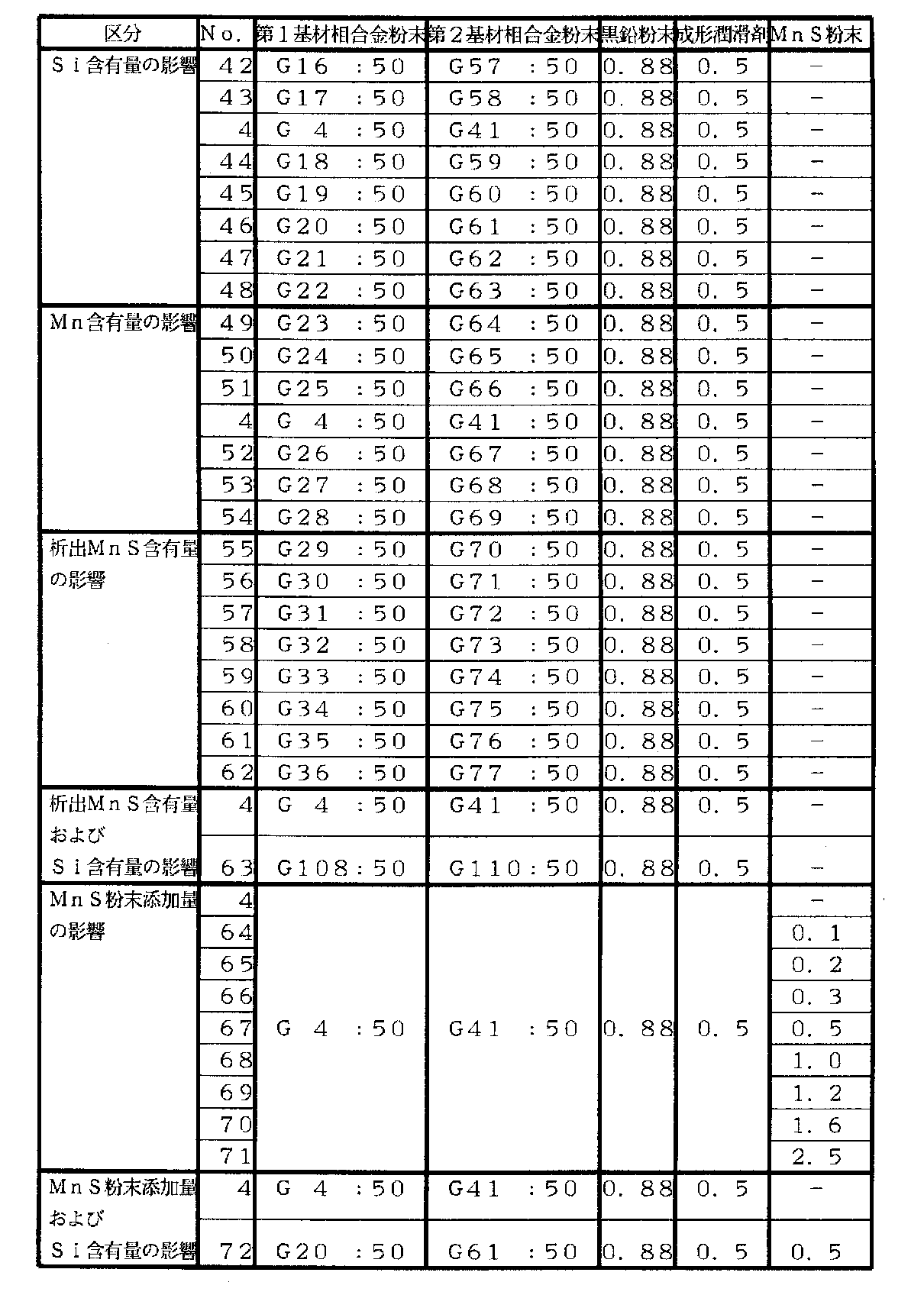
第1基材相合金粉末および第2基材相合金粉末は、平均粒径が20〜150μmのものであって、表1ないし表5に示すG1〜G113の粉末を用いた。
【0040】
そして、表6ないし表11に示す粉末の配合割合としてこれに黒鉛粉末を配合すると共に成形潤滑剤としてステアリン酸亜鉛を配合し、混合機にて30分間混合した後、6.5tonf/cm2の圧力で、内径:20mm、外径:40mm、厚さ:10mmの圧粉体に成形し、この圧粉体を分解アンモニアガス中において1180℃×30分の条件で焼結して各焼結合金を得た。なお、銅溶浸材は、前記焼結合金に銅の圧粉体をのせ、分解アンモニアガス中において1140℃×30分保持することで銅を溶融含浸させることにより作製した。また、鉛含浸材は、真空中において550℃に加熱した鉛の溶湯の中に焼結合金を浸漬した後、窒素ガス封入により8気圧に加圧することで作製した。さらに、樹脂含浸材は、アクリル系樹脂を真空含浸法により焼結合金に含浸した後、100℃の湯中で硬化することで作製した。
【0041】
次いで、このようにして作製した各焼結合金の耐摩耗性を評価するためにバルブシート形状に加工し、直列4気筒16バルブ、排気量1600ccの実機エンジンに組み込んで、排気側において、
・バルブ材:SUH−36(バルブフェース部ステライト#32盛金)
・エンジン回転数:6000rpm
・燃料:無鉛レギュラーガソリンおよび有鉛ガソリン
・試験時間:300時間
の条件で評価した。
【0042】
また、被削性の評価は、大隈式旋盤を用いて外径:φ40mm、厚さ:10mmの素材リング50個の外周を切削するにあたり、
・回転数:525rpm
・切削代:0.5mm
・送り速度:0.1mm/rev.
・切削油:なし
・工具:超硬チップ
の条件で切削したときの最大切削抵抗値で評価した。
【0043】
さらに、圧環圧強さは、外径:φ40mm、内径:φ20mm、厚さ:10mmのリングをオートグラフにてクロスヘッドスピード:0.5mm/分の条件で評価した。
【0044】
さらにまた、圧縮性の評価は、前記配合粉をアムスラー試験機にて直径:φ11.3mmの金型を用いて荷重6tonfの条件で評価した。
【0045】
これらの結果を表12〜38および図1〜図32に示す。
【0046】
【表1】
【表2】
【表3】
【表4】
【表5】
【表6】
【表7】
【表8】
【表9】
【表10】
【表11】
【表12】
【表13】
【表14】
【表15】
【表16】
【表17】
【表18】
【表19】
【表20】
【表21】
【表22】
【表23】
【表24】
【表25】
【表26】
【表27】
【表28】
【表29】
【表30】
【表31】
【表32】
【表33】
【表34】
【表35】
【表36】
【表37】
【表38】
表のNo.1〜7は、無鉛ガソリンを使用する環境下での第1基材相中のW含有量の影響を調べたものであるが、同表および図1より明らかであるように、第1基材相中のW含有量は3〜7%の範囲とするのが摩耗量を低減するうえで有効であることが認められた。
【0085】
また、表のNo.8〜14およびNo.4は、無鉛ガソリンを使用する環境下での第2基材相中のW含有量の影響を調べたものであるが、同表および図2より明らかであるように、第2基材相中のW含有量は3〜15%の範囲とするのが摩耗量を低減するうえで有効であることが認められた。
【0086】
さらに、表のNo.15〜20およびNo.4は、無鉛ガソリンを使用する環境下での第2基材相中のV含有量の影響を調べたものであるが、同表および図3より明らかであるように、第2基材相中のV含有量は2〜7%の範囲とするのが摩耗量を低減するうえで有効であることが認められた。
【0087】
さらに、表のNo.21〜25およびNo.4は、無鉛ガソリンおよび有鉛ガソリンを使用する環境下での第1基材相中のV含有量の影響を調べたものであるが、同表および図4(無鉛ガソリンの場合),図5(有鉛ガソリンの場合)より明らかであるように、第1基材相中のV含有量は1.5%以下の範囲とするのが摩耗量を低減するうえで有効であることが認められた。
【0088】
さらにまた、表のNo.26〜31およびNo.4は、無鉛ガソリンを使用する環境下での第2基材相中のCr含有量の影響を調べたものであるが、同表および図6より明らかであるように、第2基材相中のCr含有量は1〜7%の範囲とするのが摩耗量を低減するうえで有効であることが認められた。
【0089】
さらにまた、表のNo.32〜35およびNo.4は、無鉛ガソリンを使用する環境下での第1基材相中のCr含有量の影響を調べたものであるが、同表および図7より明らかであるように、第1基材相中のCr含有量は1%以下の範囲とするのが摩耗量を低減するうえで有効であることが認められた。
【0090】
さらにまた、表のNo.36〜41およびNo.4は、無鉛ガソリンを使用する環境下での第1基材相と第2基材相との配合割合の影響を調べたものであるが、同表および図8より明らかであるように、第1基材相に対する第2基材相の配合割合は20〜80wt%の範囲とするのが摩耗量を低減するうえで有効であることが認められた。
【0091】
さらにまた、表のNo.42〜48およびNo.4は、有鉛ガソリンを使用する環境下でのSi含有量の影響を調べたものであるが、同表および図9(有鉛ガソリンの場合の耐摩耗性を示す),図10(圧環強さを示す)より明らかであるように、Si含有量は0.1〜5.0%の範囲とするのが良いことが認められた。
【0092】
さらにまた、表のNo.49〜54およびNo.4は、圧環強さへのMn含有量の影響を調べたものであるが、同表および図11(圧環強さを示す)より明らかであるように、Mn含有量は0.1〜0.6%の範囲とするのが良いことが認められた。
【0093】
さらにまた、表のNo.55〜62は、析出MnS含有量の圧環強さ、圧縮性、切削抵抗への影響を調べたものであるが、同表および図12(圧環強さを示す),図13(成形圧縮性を示す),図14(切削抵抗を示す)より明らかであるように、適量のMnSを析出させたものとするのが良いことが認められた。
【0094】
さらにまた、表のNo.63およびNo.4は、有鉛ガソリンを使用する環境下での析出MnSおよびSi含有量の影響を調べたものであるが、同表より明らかであるように、MnSを適量含有させることによって切削抵抗を小さくして被削性を向上させることができると共に、Siを適量含有させることによって有鉛ガソリンを使用する環境下においても耐摩耗性を向上させることができることが認められた。
【0095】
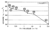
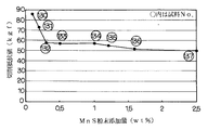
さらにまた、表のNo.64〜71およびNo.4は、MnS粉末添加量の圧環強さ、圧縮性、切削抵抗への影響を調べたものであるが、同表および図15(圧環強さを示す),図16(成形圧縮性を示す),図17(切削抵抗を示す)より明らかであるように、適量のMnS粉末を添加により分散させたものとするのが良いことが認められた。
【0096】
さらにまた、表のNo.72およびNo.4は、有鉛ガソリンを使用する環境下でのMnS粉末添加量およびSi含有量の影響を調べたものであるが、同表より明らかであるように、適量のMnS粉末を添加により分散させることによって切削抵抗を小さくして被削性を向上させることができると共に、Siを適量含有させることによって有鉛ガソリンを使用する環境下においても耐摩耗性を向上させることができることが認められた。
【0097】
表のNo.73〜78およびNo.22は、有鉛ガソリンを使用する環境下での第1基材相中のW含有量の影響を調べたものであるが、同表および図18より明らかであるように、第1基材相中のW含有量は3〜7%の範囲とするのが摩耗量を低減するうえで有効であることが認められた。
【0098】
また、表のNo.79〜85およびNo.22は、有鉛ガソリンを使用する環境下での第2基材相中のW含有量の影響を調べたものであるが、同表および図19より明らかであるように、第2基材相中のW含有量は3〜15%の範囲とするのが摩耗量を低減するうえで有効であることが認められた。
【0099】
さらに、表のNo.86〜91およびNo.22は、有鉛ガソリンを使用する環境下での第2基材相中のV含有量の影響を調べたものであるが、同表および図20より明らかであるように、第2基材相中のV含有量は2〜7%の範囲とするのが摩耗量を低減するうえで有効であることが認められた。
【0100】
さらにまた、表のNo.92〜97およびNo.22は、有鉛ガソリンを使用する環境下での第2基材相中のCr含有量の影響を調べたものであるが、同表および図21より明らかであるように、第2基材相中のCr含有量は1〜7%の範囲とするのが摩耗量を低減するうえで有効であることが認められた。
【0101】
さらにまた、表のNo.98〜101およびNo.22は、有鉛ガソリンを使用する環境下での第1基材相中のCr含有量の影響を調べたものであるが、同表および図22より明らかであるように、第1基材相中のCr含有量は1%以下の範囲とするのが摩耗量を低減するうえで有効であることが認められた。
【0102】
さらにまた、表のNo.102〜107およびNo.22は、有鉛ガソリンを使用する環境下での第1基材相と第2基材相との配合割合の影響を調べたものであるが、同表および図23より明らかであるように、第1基材相に対する2基材相の配合割合は20〜80wt%の範囲とするのが摩耗量を低減するうえで有効であることが認められた。
【0103】
さらにまた、表のNo.108〜114およびNo.22は、有鉛ガソリンを使用する環境下でのSi含有量の影響を調べたものであるが、同表および図24(有鉛ガソリンの場合の耐摩耗性を示す),図25(圧環強さを示す)より明らかであるように、Si含有量は0.1〜5.0%の範囲とするのが摩耗量を低減するうえで有効であることが認められた。
【0104】
さらにまた、表のNo.115〜120およびNo.22は、圧環強さへのMn含有量の影響を調べたものであるが、同表および図26(圧環強さを示す)より明らかであるように、Mn含有量は0.1〜0.6%の範囲とするのが良いことが認められた。
【0105】
さらにまた、表のNo.121〜128は、析出MnS含有量の圧環強さ、圧縮性、切削抵抗への影響を調べたものであるが、同表および図27(圧環強さを示す),図28(成形圧縮性を示す),図29(切削抵抗を示す)より明らかであるように、適量のMnSを析出させたものとするのが良いことが認められた。
【0106】
さらにまた、表のNo.129およびNo.22は、有鉛ガソリンを使用する環境下での析出MnSおよびSi含有量の影響を調べたものであるが、同表より明らかであるように、MnSを適量含有させることによって切削抵抗を小さくして被削性を向上させることができると共に、Siを適量含有させることによって有鉛ガソリンを使用する環境下においても耐摩耗性を向上させることができることが認められた。
【0107】
さらにまた、表のNo.130〜137およびNo.22は、MnS粉末添加量の圧環強さ、圧縮性、切削抵抗への影響を調べたものであるが、同表および図30(圧環強さを示す),図31(成形圧縮性を示す),図32(切削抵抗を示す)より明らかであるように、適量のMnS粉末を添加により分散させたものとするのが良いことが認められた。
【0108】
さらにまた、表のNo.138およびNo.22は、有鉛ガソリンを使用する環境下でのMnS粉末添加量およびSi含有量の影響を調べたものであるが、同表より明らかであるように、適量のMnS粉末を添加により分散させることによって切削抵抗を小さくして被削性を向上させることができると共に、Siを適量含有させることによって有鉛ガソリンを使用する環境下においても耐摩耗性を向上させることができることが認められた。
【0109】
さらに、表38は本発明の焼結合金の気孔中に銅を溶浸させたり、鉛を溶浸させたり、樹脂を含浸させたりした場合を示すものであるが、耐摩耗性をさらに向上させたり、被削性をさらに向上させたりすることが可能であることが認められた。
【図面の簡単な説明】
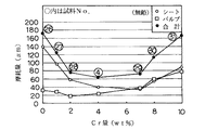
【図1】無鉛ガソリンを使用する環境下での第1基材相中のW含有量による耐摩耗性への影響を調べた結果を示すグラフである。
【図2】無鉛ガソリンを使用する環境下での第2基材相中のW含有量による耐摩耗性への影響を調べた結果を示すグラフである。
【図3】無鉛ガソリンを使用する環境下での第2基材相中のV含有量による耐摩耗性への影響を調べた結果を示すグラフである。
【図4】無鉛ガソリンを使用する環境下での第1基材相中のV含有量による耐摩耗性への影響を調べた結果を示すグラフである。
【図5】有鉛ガソリンを使用する環境下での第1基材相中のV含有量による耐摩耗性への影響を調べた結果を示すグラフである。
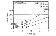
【図6】無鉛ガソリンを使用する環境下での第2基材相中のCr含有量による耐摩耗性への影響を調べた結果を示すグラフである。
【図7】無鉛ガソリンを使用する環境下での第1基材相中のCr含有量による耐摩耗性への影響を調べた結果を示すグラフである。
【図8】無鉛ガソリンを使用する環境下での第1基材相と第2基材相との配合割合による耐摩耗性への影響を調べた結果を示すグラフである。
【図9】有鉛ガソリンを使用する環境下でのSi含有量による耐摩耗性への影響を調べた結果を示すグラフである。
【図10】Si含有量による圧環強さへの影響を調べた結果を示すグラフである。
【図11】Mn含有量による圧環強さへの影響を調べた結果を示すグラフである。
【図12】析出MnS含有量による圧環強さへの影響を調べた結果を示すグラフである。
【図13】析出MnS含有量による成形性への影響を調べた結果を示すグラフである。
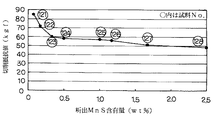
【図14】析出MnS含有量による被削性への影響を調べた結果を示すグラフである。
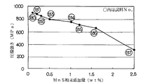
【図15】MnS粉末添加量による圧環強さへの影響を調べた結果を示すグラフである。
【図16】MnS粉末添加量による成形性への影響を調べた結果を示すグラフである。
【図17】MnS粉末添加量による被削性への影響を調べた結果を示すグラフである。
【図18】有鉛ガソリンを使用する環境下での第1基材相中のW含有量による耐摩耗性への影響を調べた結果を示すグラフである。
【図19】有鉛ガソリンを使用する環境下での第2基材相中のW含有量による耐摩耗性への影響を調べた結果を示すグラフである。
【図20】有鉛ガソリンを使用する環境下での第2基材相中のV含有量による耐摩耗性への影響を調べた結果を示すグラフである。
【図21】有鉛ガソリンを使用する環境下での第2基材相中のCr含有量による耐摩耗性への影響を調べた結果を示すグラフである。
【図22】有鉛ガソリンを使用する環境下での第1基材相中のCr含有量による耐摩耗性への影響を調べた結果を示すグラフである。
【図23】有鉛ガソリンを使用する環境下での第1基材相と第2基材相との配合割合による耐摩耗性への影響を調べた結果を示すグラフである。
【図24】有鉛ガソリンを使用する環境下でのSi含有量による耐摩耗性への影響を調べた結果を示すグラフである。
【図25】Si含有量による圧環強さへの影響を調べた結果を示すグラフである。
【図26】Mn含有量による圧環強さへの影響を調べた結果を示すグラフである。
【図27】析出MnS含有量による圧環強さへの影響を調べた結果を示すグラフである。
【図28】析出MnS含有量による成形性への影響を調べた結果を示すグラフである。
【図29】析出MnS含有量による被削性への影響を調べた結果を示すグラフである。
【図30】MnS粉末添加量による圧環強さへの影響を調べた結果を示すグラフである。
【図31】MnS粉末添加量による成形性への影響を調べた結果を示すグラフである。
【図32】MnS粉末添加量による被削性への影響を調べた結果を示すグラフである。[0001]
BACKGROUND OF THE INVENTION
The present invention relates to a high-temperature wear-resistant iron-based sintered alloy suitably used as a material for parts required to have excellent wear resistance at high temperatures, such as valve seats used in internal combustion engines, for example. Is.
[0002]
[Prior art]
Examples of conventional wear-resistant materials include high-Co materials disclosed in JP-B-5-55593 and JP-A-7-233454, JP-A-5-9667, and JP-B-1-51539. Many other materials are known, including a material in which fine carbides such as W, Mo, V, Nb, Ti, and Ta are dispersed in the matrix in order to improve the wear resistance disclosed in the above.
[0003]
[Problems to be solved by the invention]
However, under the circumstances where the demand for higher performance of internal combustion engines, high temperature wear resistance in valve seats, corrosion resistance improvement and machinability improvement associated with leaded and unleaded gasoline is further increased, the above-mentioned conventional high Co system The material of this type is economically disadvantageous, and in the material in which fine carbides are dispersed in the matrix, the type of carbide and the amount of carbide are not optimal, and both self-wear resistance and opponent attack resistance are compatible. Since there was a problem that it was difficult and the required performance could not be sufficiently satisfied, it was an issue to solve such a problem.
[0004]
OBJECT OF THE INVENTION
The present invention has been made paying attention to such a conventional problem, and can improve its own wear resistance and reduce the aggression against the counterpart material. An object of the present invention is to provide a high-temperature wear-resistant sintered alloy that can satisfy both of the required performance by making it possible to achieve both self-wear resistance and opponent attack resistance.
[0005]
[Means for Solving the Problems]
As described in
[0006]
In addition, the high temperature wear resistant sintered alloy according to another embodiment of the present invention has a weight ratio of W: 3 to 13.4%, V: 0.8-5.9%, Cr: 0.2-5.6%, Si: 0.1-0.6%, Mn: 0.1-0.6%, C: 0.6-2. 2%, balance Fe and impurities, and W: 3-7%, V: 0.5-1.5%, Cr: 1% or less, Si: 0.1-0.6% , Mn: 0.1 to 0.6%, C: 2.2% or less, W: 3 to 15%, V: 2 to 7%, Cr: 1 to 7%, Si: 0.1 to 0.6%, Mn: 0.1 to 0.6%, C: 2.2% or less, the second base material phase composed of the remaining Fe and impurities is 20 to 80 wt. These two phases are distributed in patches. It is characterized in that was assumed to exhibit the organization.
[0007]
Furthermore, the high-temperature wear-resistant sintered alloy according to still another embodiment of the present invention has an overall composition of W: 3 to 13.4%, V, as described in
[0008]
Furthermore, as described in
[0009]
Furthermore, as described in
[0010]
Furthermore, the high-temperature wear-resistant sintered alloy according to still another embodiment of the present invention has a total composition of W: 3 to 13.4% by weight, as described in
[0011]
Furthermore, the high-temperature wear-resistant sintered alloy according to still another embodiment of the present invention has a total composition of W: 3 to 13.4% by weight, as described in
[0012]
Furthermore, as described in
[0013]
Furthermore, the high-temperature wear-resistant sintered alloy according to still another embodiment of the present invention is a sintered bond according to any one of
[0014]
Furthermore, a high temperature wear resistant sintered alloy according to still another embodiment of the present invention is as described in claim 11, and is defined in
[0015]
Furthermore, a high temperature wear resistant sintered alloy according to still another embodiment of the present invention, as described in
[0016]
Furthermore, the high-temperature wear-resistant sintered alloy according to still another embodiment of the present invention is as described in claim 13, A feature of the present invention is that the pores of the sintered alloy according to any one of 9 and 10 are impregnated with an acrylic resin.
[0017]
【The invention's effect】
In the high temperature wear resistant sintered alloy according to the present invention, as described in
[0018]
And, as described in
[0019]
Further, as described in
[0020]
Furthermore, as described in claim 9, by dispersing 0.3 to 1.6 wt% of MnS in the grain boundaries or pores of the sintered alloy, similarly to the case where MnS is precipitated in the matrix. The remarkably excellent effect that the machinability can be greatly improved is brought about.
[0021]
Moreover, as described in
[0022]
Therefore, the high-temperature wear-resistant sintered alloy according to the present invention has a remarkable effect that it can make a great improvement in both economical efficiency and wear resistance as compared with the conventional high-Co material.
[0023]
[Effects of the Invention]
As a first invention according to
[0024]
In the first base phase constituting the high-temperature wear-resistant sintered alloy of the present invention, when the W content exceeds 7%, the aggressiveness to the valve is increased, and when it is less than 3%, the wear resistance of the valve seat is increased. Decreases. Further, Cr may be omitted because it increases the aggressiveness to the bulb, but may be 1% or less due to diffusion from the second base phase during sintering.
[0025]
Similarly, in the second base phase, if the W and V contents exceed 15% and 7%, respectively, the aggressiveness to the valve is increased, and if the content is less than 3% and 2%, the wear resistance of the valve seat increases. descend. Furthermore, hardenability is improved by containing 1 to 7% of Cr in the second base phase, and harder MC type V carbide is precipitated, so that it is harder than the first base phase. Thus, the hardness becomes patchy and good wear resistance is obtained. And if Cr content exceeds 7%, the attacking property to a valve | bulb will increase, and if less than 1%, the abrasion resistance of a valve seat will fall.
[0026]
Si is effective as a deoxidizer and is contained in the substrate. However, if the Si content exceeds 0.6%, the strength decreases, and even if the Si content is less than 0.1%, the sinterability is inhibited and the strength is reduced. Decreases.
[0027]
High strength is obtained when Mn is 0.1% or more, but when it exceeds 0.6%, the sinterability is inhibited and the strength is lowered.
[0028]
Furthermore, when the ratio of the first base material phase to the second base material phase is less than 20% of the hard second base material material with respect to the first base material phase, the wear resistance of the valve seat decreases, and 80% Beyond that, the aggression on the valve increases.
[0029]
As a second invention according to
[0030]
As a third invention according to
[0031]
As a fourth invention according to
[0032]
As a fifth invention according to
[0033]
As a sixth invention according to
[0034]
As a seventh invention according to
[0035]
As an eighth invention according to
[0036]
In the sintered alloy according to claim 9 or claim 10, 0.3 to 1.6 wt% of MnS is dispersed in the grain boundaries or pores, respectively, and the amount of MnS dispersed is 0.3 wt%. Although the machinability can be greatly improved by the above, if the amount of MnS dispersed is too large, the compressibility of the powder during the molding process will be affected, and the strength of the resulting sintered product will be reduced. Therefore, it is good to set it as 1.6 wt% or less.
[0037]
The sintered alloy according to
[0038]
【Example】
The high-temperature wear-resistant sintered alloy according to the present invention will be described more specifically with reference to examples and comparative examples.
[0039]
The first base phase alloy powder and the second base phase alloy powder had an average particle size of 20 to 150 μm, and G1 to G113 powders shown in Tables 1 to 5 were used.
[0040]
Then, graphite powder was blended with the powder as shown in Tables 6 to 11, and zinc stearate was blended as a molding lubricant. After mixing with a mixer for 30 minutes, 6.5 tonf / cm 2 Is molded into a green compact with an inner diameter of 20 mm, an outer diameter of 40 mm, and a thickness of 10 mm, and the green compact is sintered in decomposed ammonia gas under conditions of 1180 ° C. × 30 minutes for each sintering. I got money. The copper infiltrant was produced by placing copper compact on the sintered alloy and melt impregnating copper by holding it in decomposed ammonia gas at 1140 ° C. for 30 minutes. The lead-impregnated material was prepared by immersing the sintered alloy in a molten lead heated to 550 ° C. in a vacuum and then pressurizing to 8 atm with nitrogen gas filling. Further, the resin-impregnated material was prepared by impregnating a sintered alloy with an acrylic resin by a vacuum impregnation method and then curing in 100 ° C. hot water.
[0041]
Next, in order to evaluate the wear resistance of each sintered alloy produced in this way, it was processed into a valve seat shape, incorporated in an actual engine with an in-line 4-
・ Valve material: SUH-36 (Valve face section stellite # 32 primed)
・ Engine speed: 6000rpm
・ Fuel: Unleaded regular gasoline and leaded gasoline
・ Test time: 300 hours
Evaluation was performed under the conditions of
[0042]
In addition, the machinability is evaluated by cutting the outer periphery of 50 material rings having an outer diameter of 40 mm and a thickness of 10 mm using a large lathe.
・ Rotation speed: 525rpm
・ Cutting allowance: 0.5mm
-Feeding speed: 0.1 mm / rev.
・ Cutting oil: None
・ Tool: Carbide insert
The maximum cutting resistance value when cutting under the conditions of
[0043]
Further, the crushing strength was evaluated by using an autograph for a ring having an outer diameter of φ40 mm, an inner diameter of φ20 mm, and a thickness of 10 mm, with a crosshead speed of 0.5 mm / min.
[0044]
Furthermore, the compressibility was evaluated using the Amsler tester with a mold having a diameter of φ 11.3 mm and a load of 6 tonf.
[0045]
These results are shown in Tables 12 to 38 and FIGS.
[0046]
[Table 1]
[Table 2]
[Table 3]
[Table 4]
[Table 5]
[Table 6]
[Table 7]
[Table 8]
[Table 9]
[Table 10]
[Table 11]
[Table 12]
[Table 13]
[Table 14]
[Table 15]
[Table 16]
[Table 17]
[Table 18]
[Table 19]
[Table 20]
[Table 21]
[Table 22]
[Table 23]
[Table 24]
[Table 25]
[Table 26]
[Table 27]
[Table 28]
[Table 29]
[Table 30]
[Table 31]
[Table 32]
[Table 33]
[Table 34]
[Table 35]
[Table 36]
[Table 37]
[Table 38]
No. in the table. Nos. 1 to 7 show the influence of the W content in the first base material phase in an environment where unleaded gasoline is used. As is clear from the table and FIG. It was confirmed that the W content in the phase was in the range of 3 to 7% in terms of reducing the wear amount.
[0085]
In the table, No. 8-14 and no. 4 is an investigation of the influence of the W content in the second base phase in an environment where unleaded gasoline is used. As is clear from the table and FIG. It was recognized that the W content in the range of 3 to 15% is effective in reducing the wear amount.
[0086]
In addition, No. in the table. 15-20 and no. 4 is an investigation of the influence of the V content in the second base phase in an environment where unleaded gasoline is used. As is clear from the table and FIG. 3, in the second base phase, It was confirmed that the V content in the range of 2 to 7% is effective in reducing the wear amount.
[0087]
In addition, No. in the table. 21-25 and no. 4 shows the effect of the V content in the first base phase in an environment where unleaded gasoline and leaded gasoline are used. Table 4 and FIG. 4 (in the case of unleaded gasoline), FIG. As is clear from (in the case of leaded gasoline), it is recognized that it is effective in reducing the amount of wear to make the V content in the first base phase within 1.5% or less. It was.
[0088]
Furthermore, No. in the table. 26-31 and no. 4 is an investigation of the effect of Cr content in the second base phase under an environment where unleaded gasoline is used. As is clear from the table and FIG. It was confirmed that the Cr content in the range of 1 to 7% is effective in reducing the wear amount.
[0089]
Furthermore, No. in the table. 32-35 and no. 4 is an investigation of the effect of Cr content in the first base phase in an environment where unleaded gasoline is used. As is clear from the table and FIG. It was confirmed that the Cr content in the range of 1% or less is effective in reducing the wear amount.
[0090]
Furthermore, No. in the table. 36-41 and no. 4 is an investigation of the influence of the blending ratio of the first base phase and the second base phase in an environment where unleaded gasoline is used. As is clear from the table and FIG. It was recognized that the blending ratio of the second base material phase with respect to the one base material phase was in the range of 20 to 80 wt% in terms of reducing the wear amount.
[0091]
Furthermore, No. in the table. 42-48 and no. Fig. 4 shows the effect of Si content in an environment where leaded gasoline is used. The table and Fig. 9 (showing wear resistance in the case of leaded gasoline) and Fig. 10 (crushing strength) As is clear from the above, it was recognized that the Si content should be in the range of 0.1 to 5.0%.
[0092]
Furthermore, No. in the table. 49-54 and no. 4 is an investigation of the influence of the Mn content on the crushing strength. As is clear from the table and FIG. 11 (showing the crushing strength), the Mn content is 0.1 to 0. It was recognized that a range of 6% was good.
[0093]
Furthermore, No. in the table. Nos. 55 to 62 are the investigations on the influence of the precipitated MnS content on the crushing strength, compressibility, and cutting resistance. The table and FIG. 12 (showing crushing strength) and FIG. As is clear from FIG. 14 (showing cutting resistance), it was recognized that an appropriate amount of MnS should be deposited.
[0094]
Furthermore, No. in the table. 63 and no. No. 4 is an investigation of the effects of precipitated MnS and Si contents in an environment where leaded gasoline is used. As is clear from the table, cutting resistance is reduced by adding an appropriate amount of MnS. Thus, it was recognized that the machinability can be improved and that the wear resistance can be improved even in an environment where leaded gasoline is used by containing an appropriate amount of Si.
[0095]
Furthermore, No. in the table. 64-71 and no. 4 shows the effect of the added amount of MnS powder on the crushing strength, compressibility, and cutting resistance. Table 4 and FIG. 15 (showing crushing strength) and FIG. 16 (showing molding compressibility) As is clear from FIG. 17 (showing cutting resistance), it was recognized that an appropriate amount of MnS powder should be dispersed by addition.
[0096]
Furthermore, No. in the table. 72 and no. 4 shows the effect of the added amount of MnS powder and the Si content in an environment where leaded gasoline is used. As is clear from the table, an appropriate amount of MnS powder is dispersed by addition. As a result, it was found that the cutting resistance can be reduced to improve the machinability, and the wear resistance can be improved even in an environment where leaded gasoline is used by containing an appropriate amount of Si.
[0097]
No. in the table. 73-78 and no. 22 is an investigation of the influence of the W content in the first base phase in an environment where leaded gasoline is used. As is apparent from the table and FIG. It was recognized that the W content in the range of 3 to 7% is effective in reducing the wear amount.
[0098]
In the table, No. 79-85 and no. No. 22 is an investigation of the influence of the W content in the second base phase under an environment where leaded gasoline is used. As is apparent from the table and FIG. It was recognized that the content of W in the range of 3 to 15% is effective in reducing the wear amount.
[0099]
In addition, No. in the table. 86-91 and no. No. 22 is an investigation of the influence of the V content in the second base phase in an environment where leaded gasoline is used. As is clear from the table and FIG. It was recognized that the content of V in the range of 2 to 7% is effective in reducing the amount of wear.
[0100]
Furthermore, No. in the table. 92-97 and no. 22 shows the effect of the Cr content in the second base phase under the environment where leaded gasoline is used. As is clear from the table and FIG. 21, the second base phase It was recognized that the Cr content in the range of 1 to 7% is effective in reducing the wear amount.
[0101]
Furthermore, No. in the table. 98-101 and no. No. 22 shows the effect of Cr content in the first base phase in an environment where leaded gasoline is used. As is clear from the table and FIG. It was recognized that the Cr content in the range of 1% or less is effective in reducing the wear amount.
[0102]
Furthermore, No. in the table. 102-107 and no. No. 22 is an investigation of the influence of the blending ratio of the first base phase and the second base phase in an environment where leaded gasoline is used. As is clear from the table and FIG. It was recognized that the blending ratio of the two base phases to the first base phase was in the range of 20 to 80 wt% in terms of reducing the amount of wear.
[0103]
Furthermore, No. in the table. 108-114 and no. 22 shows the effect of Si content in an environment where leaded gasoline is used. The table and FIG. 24 (shows the wear resistance in the case of leaded gasoline) and FIG. As is clear from the above, it was confirmed that the Si content in the range of 0.1 to 5.0% is effective in reducing the wear amount.
[0104]
Furthermore, No. in the table. 115-120 and No. No. 22 is an investigation of the influence of the Mn content on the crushing strength. As is clear from the table and FIG. 26 (showing the crushing strength), the Mn content is 0.1 to 0.2. It was recognized that a range of 6% was good.
[0105]
Furthermore, No. in the table. Nos. 121 to 128 were obtained by examining the influence of the precipitated MnS content on the crushing strength, compressibility, and cutting resistance. The table and FIG. 27 (showing crushing strength) and FIG. As is clear from FIG. 29 (showing cutting resistance), it was recognized that an appropriate amount of MnS should be deposited.
[0106]
Furthermore, No. in the table. 129 and no. No. 22 is an investigation of the effects of precipitated MnS and Si contents in an environment where leaded gasoline is used. As is clear from the table, cutting resistance is reduced by adding an appropriate amount of MnS. Thus, it was recognized that the machinability can be improved and that the wear resistance can be improved even in an environment where leaded gasoline is used by containing an appropriate amount of Si.
[0107]
Furthermore, No. in the table. 130-137 and no. 22 shows the effect of the added amount of MnS powder on the crushing strength, compressibility, and cutting resistance. The table and FIG. 30 (showing crushing strength) and FIG. 31 (showing molding compressibility) As is clear from FIG. 32 (showing cutting resistance), it was recognized that an appropriate amount of MnS powder should be dispersed by addition.
[0108]
Furthermore, No. in the table. 138 and no. No. 22 is a study of the effects of MnS powder addition amount and Si content in an environment where leaded gasoline is used. As is clear from the table, an appropriate amount of MnS powder is dispersed by addition. As a result, it was found that the cutting resistance can be reduced to improve the machinability, and the wear resistance can be improved even in an environment where leaded gasoline is used by containing an appropriate amount of Si.
[0109]
Further, Table 38 shows the case where copper is infiltrated into the pores of the sintered alloy of the present invention, lead is infiltrated, or the resin is impregnated, but the wear resistance is further improved. It was recognized that the machinability could be further improved.
[Brief description of the drawings]
FIG. 1 is a graph showing the results of examining the influence on the wear resistance of the W content in a first base phase under an environment where unleaded gasoline is used.
FIG. 2 is a graph showing the results of examining the influence on the wear resistance by the W content in the second base phase under an environment where unleaded gasoline is used.
FIG. 3 is a graph showing the results of examining the influence on the wear resistance by the V content in the second base phase under an environment in which unleaded gasoline is used.
FIG. 4 is a graph showing the results of examining the influence on the wear resistance by the V content in the first base phase in an environment where unleaded gasoline is used.
FIG. 5 is a graph showing the results of examining the influence on the wear resistance by the V content in the first base phase in an environment where leaded gasoline is used.
FIG. 6 is a graph showing the results of examining the influence on the wear resistance by the Cr content in the second base phase under an environment in which unleaded gasoline is used.
FIG. 7 is a graph showing the results of examining the effect of Cr content in the first base phase on wear resistance in an environment where unleaded gasoline is used.
FIG. 8 is a graph showing the results of examining the influence on the wear resistance by the blending ratio of the first base phase and the second base phase in an environment where unleaded gasoline is used.
FIG. 9 is a graph showing the results of examining the effect of Si content on wear resistance in an environment where leaded gasoline is used.
FIG. 10 is a graph showing the results of examining the influence of the Si content on the crushing strength.
FIG. 11 is a graph showing the results of examining the influence of the Mn content on the crushing strength.
FIG. 12 is a graph showing the results of examining the influence on the crushing strength by the precipitated MnS content.
FIG. 13 is a graph showing the results of examining the influence of the precipitated MnS content on moldability.
FIG. 14 is a graph showing the results of investigating the effect of the precipitated MnS content on machinability.
FIG. 15 is a graph showing the results of examining the influence of the added amount of MnS powder on the crushing strength.
FIG. 16 is a graph showing the results of examining the influence on the moldability by the amount of MnS powder added.
FIG. 17 is a graph showing the results of examining the effect on machinability by the amount of MnS powder added.
FIG. 18 is a graph showing the results of examining the influence on the wear resistance by the W content in the first base phase under an environment where leaded gasoline is used.
FIG. 19 is a graph showing the results of examining the influence on the wear resistance by the W content in the second base phase under an environment in which leaded gasoline is used.
FIG. 20 is a graph showing the results of examining the influence on the wear resistance by the V content in the second base phase under an environment where leaded gasoline is used.
FIG. 21 is a graph showing the results of examining the influence on the wear resistance by the Cr content in the second base phase under an environment where leaded gasoline is used.
FIG. 22 is a graph showing the results of examining the influence on the wear resistance by the Cr content in the first base phase under an environment in which leaded gasoline is used.
FIG. 23 is a graph showing the results of examining the influence on the wear resistance by the blending ratio of the first base phase and the second base phase in an environment where leaded gasoline is used.
FIG. 24 is a graph showing the results of investigating the influence of Si content on wear resistance in an environment where leaded gasoline is used.
FIG. 25 is a graph showing the results of examining the influence of the Si content on the crushing strength.
FIG. 26 is a graph showing the results of examining the influence of the Mn content on the crushing strength.
FIG. 27 is a graph showing the results of examining the influence of the precipitated MnS content on the crushing strength.
FIG. 28 is a graph showing the results of examining the influence of the precipitated MnS content on moldability.
FIG. 29 is a graph showing the results of examining the effect on the machinability by the content of precipitated MnS.
FIG. 30 is a graph showing the results of examining the influence of the added amount of MnS powder on the crushing strength.
FIG. 31 is a graph showing the results of examining the influence on the moldability by the amount of MnS powder added.
FIG. 32 is a graph showing the results of examining the influence on the machinability by the amount of MnS powder added.
Claims (13)
Priority Applications (3)
| Application Number | Priority Date | Filing Date | Title |
|---|---|---|---|
| JP09416597A JP3661823B2 (en) | 1996-04-15 | 1997-04-11 | High temperature wear resistant sintered alloy |
| GB9707598A GB2312217B (en) | 1996-04-15 | 1997-04-15 | High-temperature wear-resistant sintered alloy |
| KR1019970013707A KR100234601B1 (en) | 1996-04-15 | 1997-04-15 | High Temperature Abrasion Resistance Sintered Alloy |
Applications Claiming Priority (5)
| Application Number | Priority Date | Filing Date | Title |
|---|---|---|---|
| JP8-92752 | 1996-04-15 | ||
| JP9275296 | 1996-04-15 | ||
| JP5794397 | 1997-03-12 | ||
| JP9-57943 | 1997-03-12 | ||
| JP09416597A JP3661823B2 (en) | 1996-04-15 | 1997-04-11 | High temperature wear resistant sintered alloy |
Publications (2)
| Publication Number | Publication Date |
|---|---|
| JPH10310851A JPH10310851A (en) | 1998-11-24 |
| JP3661823B2 true JP3661823B2 (en) | 2005-06-22 |
Family
ID=27296436
Family Applications (1)
| Application Number | Title | Priority Date | Filing Date |
|---|---|---|---|
| JP09416597A Expired - Fee Related JP3661823B2 (en) | 1996-04-15 | 1997-04-11 | High temperature wear resistant sintered alloy |
Country Status (3)
| Country | Link |
|---|---|
| JP (1) | JP3661823B2 (en) |
| KR (1) | KR100234601B1 (en) |
| GB (1) | GB2312217B (en) |
Families Citing this family (4)
| Publication number | Priority date | Publication date | Assignee | Title |
|---|---|---|---|---|
| GB2342925B (en) | 1998-08-19 | 2001-05-16 | Hitachi Powdered Metals | Sintered alloy having improved wear resistance and process for producing the same |
| JP3878355B2 (en) | 1999-04-12 | 2007-02-07 | 日立粉末冶金株式会社 | High temperature wear resistant sintered alloy |
| GB9917510D0 (en) | 1999-07-27 | 1999-09-29 | Federal Mogul Sintered Prod | Sintered steel material |
| JP7022607B2 (en) * | 2018-01-31 | 2022-02-18 | 日本ピストンリング株式会社 | Valve seat and connection structure between valve seat and cylinder head |
Family Cites Families (2)
| Publication number | Priority date | Publication date | Assignee | Title |
|---|---|---|---|---|
| GB2116207A (en) * | 1982-03-02 | 1983-09-21 | Marko Materials Inc | Improved tool steels which contain boron and have been processed using a rapid solidification process and method |
| JPS6365056A (en) * | 1986-09-05 | 1988-03-23 | Nissan Motor Co Ltd | Wear resistant sintered iron alloy |
-
1997
- 1997-04-11 JP JP09416597A patent/JP3661823B2/en not_active Expired - Fee Related
- 1997-04-15 KR KR1019970013707A patent/KR100234601B1/en not_active Expired - Fee Related
- 1997-04-15 GB GB9707598A patent/GB2312217B/en not_active Expired - Fee Related
Also Published As
| Publication number | Publication date |
|---|---|
| JPH10310851A (en) | 1998-11-24 |
| KR100234601B1 (en) | 1999-12-15 |
| KR19980076838A (en) | 1998-11-16 |
| GB2312217B (en) | 1998-03-04 |
| GB9707598D0 (en) | 1997-06-04 |
| GB2312217A (en) | 1997-10-22 |
Similar Documents
| Publication | Publication Date | Title |
|---|---|---|
| JP3878355B2 (en) | High temperature wear resistant sintered alloy | |
| JP3952344B2 (en) | Wear-resistant iron-based sintered alloy material for valve seat and valve seat made of iron-based sintered alloy | |
| EP0480495B1 (en) | Sintered ferrous-based material | |
| KR940008944B1 (en) | Wear-resistant sintered iron alloy of hard particle dispersion type and its manufacturing method and valve seat formed therefrom | |
| JP3786267B2 (en) | Method for producing a valve seat made of an Fe-based sintered alloy that exhibits excellent wear resistance under high surface pressure application conditions | |
| US5188659A (en) | Sintered materials and method thereof | |
| US5895517A (en) | Sintered Fe alloy for valve seat | |
| WO2009122985A1 (en) | Iron-base sintered alloy for valve sheet and valve sheet for internal combustion engine | |
| JP2002129296A (en) | Iron-base sintered alloy material for valve seat, and valve seat made of iron-base sintered alloy | |
| JP4584158B2 (en) | Valve seat material made of iron-based sintered alloy for internal combustion engines | |
| JP3661823B2 (en) | High temperature wear resistant sintered alloy | |
| US6251157B1 (en) | Sintered alloy having superb wear resistance and process for producing the same | |
| JPS5940217B2 (en) | Fe-based sintered alloy with wear resistance | |
| EP0277239A1 (en) | Abrasion-resistant sintered alloy and process for its production | |
| JPH0555592B2 (en) | ||
| JPS60251258A (en) | Iron system sintered alloy for valve sheet | |
| JP3447032B2 (en) | Wear resistant sintered alloy and method for producing the same | |
| JP3275727B2 (en) | Method for producing two-layer valve seat made of Fe-based sintered alloy with excellent wear resistance | |
| JPH11209855A (en) | Valve seat made of Fe-based sintered alloy that exhibits excellent wear resistance under conditions of high surface pressure | |
| JPH0543998A (en) | Valve seat made of metal-filled fe-base sintered alloy extremely reduced in attack on mating material | |
| JPS5974265A (en) | Heat and wear resistant sintered alloy | |
| JPH07116489B2 (en) | Manufacturing method of infiltration valve seat ring | |
| JP2643740B2 (en) | Two-layer valve seat made of copper infiltrated iron-based sintered alloy for internal combustion engines | |
| JPS63203754A (en) | Sintered iron alloy having wear resistance at high temperature | |
| JP3230138B2 (en) | Internal-combustion engine tappet member having high joining strength with chip material |
Legal Events
| Date | Code | Title | Description |
|---|---|---|---|
| A131 | Notification of reasons for refusal |
Free format text: JAPANESE INTERMEDIATE CODE: A131 Effective date: 20041209 |
|
| A521 | Written amendment |
Free format text: JAPANESE INTERMEDIATE CODE: A523 Effective date: 20050203 |
|
| TRDD | Decision of grant or rejection written | ||
| A01 | Written decision to grant a patent or to grant a registration (utility model) |
Free format text: JAPANESE INTERMEDIATE CODE: A01 Effective date: 20050316 |
|
| A61 | First payment of annual fees (during grant procedure) |
Free format text: JAPANESE INTERMEDIATE CODE: A61 Effective date: 20050316 |
|
| R150 | Certificate of patent or registration of utility model |
Free format text: JAPANESE INTERMEDIATE CODE: R150 |
|
| FPAY | Renewal fee payment (event date is renewal date of database) |
Free format text: PAYMENT UNTIL: 20090401 Year of fee payment: 4 |
|
| FPAY | Renewal fee payment (event date is renewal date of database) |
Free format text: PAYMENT UNTIL: 20090401 Year of fee payment: 4 |
|
| FPAY | Renewal fee payment (event date is renewal date of database) |
Free format text: PAYMENT UNTIL: 20100401 Year of fee payment: 5 |
|
| FPAY | Renewal fee payment (event date is renewal date of database) |
Free format text: PAYMENT UNTIL: 20110401 Year of fee payment: 6 |
|
| FPAY | Renewal fee payment (event date is renewal date of database) |
Free format text: PAYMENT UNTIL: 20120401 Year of fee payment: 7 |
|
| FPAY | Renewal fee payment (event date is renewal date of database) |
Free format text: PAYMENT UNTIL: 20130401 Year of fee payment: 8 |
|
| FPAY | Renewal fee payment (event date is renewal date of database) |
Free format text: PAYMENT UNTIL: 20130401 Year of fee payment: 8 |
|
| S531 | Written request for registration of change of domicile |
Free format text: JAPANESE INTERMEDIATE CODE: R313532 |
|
| FPAY | Renewal fee payment (event date is renewal date of database) |
Free format text: PAYMENT UNTIL: 20130401 Year of fee payment: 8 |
|
| R350 | Written notification of registration of transfer |
Free format text: JAPANESE INTERMEDIATE CODE: R350 |
|
| FPAY | Renewal fee payment (event date is renewal date of database) |
Free format text: PAYMENT UNTIL: 20130401 Year of fee payment: 8 |
|
| S111 | Request for change of ownership or part of ownership |
Free format text: JAPANESE INTERMEDIATE CODE: R313117 |
|
| FPAY | Renewal fee payment (event date is renewal date of database) |
Free format text: PAYMENT UNTIL: 20130401 Year of fee payment: 8 |
|
| R350 | Written notification of registration of transfer |
Free format text: JAPANESE INTERMEDIATE CODE: R350 |
|
| FPAY | Renewal fee payment (event date is renewal date of database) |
Free format text: PAYMENT UNTIL: 20130401 Year of fee payment: 8 |
|
| FPAY | Renewal fee payment (event date is renewal date of database) |
Free format text: PAYMENT UNTIL: 20140401 Year of fee payment: 9 |
|
| LAPS | Cancellation because of no payment of annual fees |