JP3661900B2 - Particle size detection apparatus and method - Google Patents
Particle size detection apparatus and method Download PDFInfo
- Publication number
- JP3661900B2 JP3661900B2 JP33655396A JP33655396A JP3661900B2 JP 3661900 B2 JP3661900 B2 JP 3661900B2 JP 33655396 A JP33655396 A JP 33655396A JP 33655396 A JP33655396 A JP 33655396A JP 3661900 B2 JP3661900 B2 JP 3661900B2
- Authority
- JP
- Japan
- Prior art keywords
- light
- measured
- angle
- projecting
- particle size
- Prior art date
- Legal status (The legal status is an assumption and is not a legal conclusion. Google has not performed a legal analysis and makes no representation as to the accuracy of the status listed.)
- Expired - Fee Related
Links
- 239000002245 particle Substances 0.000 title claims description 47
- 238000001514 detection method Methods 0.000 title claims description 18
- 238000000034 method Methods 0.000 title description 8
- 238000005259 measurement Methods 0.000 claims description 10
- 230000007423 decrease Effects 0.000 claims description 8
- 238000010586 diagram Methods 0.000 description 8
- XEEYBQQBJWHFJM-UHFFFAOYSA-N Iron Chemical compound [Fe] XEEYBQQBJWHFJM-UHFFFAOYSA-N 0.000 description 6
- 239000000571 coke Substances 0.000 description 6
- 230000003287 optical effect Effects 0.000 description 6
- 238000000149 argon plasma sintering Methods 0.000 description 5
- 238000005204 segregation Methods 0.000 description 5
- 238000005516 engineering process Methods 0.000 description 3
- 229910052742 iron Inorganic materials 0.000 description 3
- 230000000694 effects Effects 0.000 description 2
- 230000035945 sensitivity Effects 0.000 description 2
- 230000003247 decreasing effect Effects 0.000 description 1
- 239000006185 dispersion Substances 0.000 description 1
- 239000000835 fiber Substances 0.000 description 1
- 239000000446 fuel Substances 0.000 description 1
- 238000002844 melting Methods 0.000 description 1
- 230000008018 melting Effects 0.000 description 1
- 239000000203 mixture Substances 0.000 description 1
- 230000005855 radiation Effects 0.000 description 1
- 239000002994 raw material Substances 0.000 description 1
- 238000004441 surface measurement Methods 0.000 description 1
Images

Landscapes
- Length Measuring Devices By Optical Means (AREA)
Description
【0001】
【発明の属する技術分野】
本発明は、高炉炉頂面における粒度偏析を測定する粒度検出装置及び方法に関する。
【0002】
【従来の技術】
鉄鉱石を溶解する高炉では、通常、炉の上部からコークスと鉄鉱石を交互に装入し、その後攪拌機により炉頂面のプロファイルが断面V字形となるように設定する。炉頂プロファイルを所望のV字形にすることは高炉の燃費を節約する上で非常に重要な意味をもっており、従って炉頂プロファイルを正確に測定する手段が要求される。
【0003】
この要求を満たすために、特公昭56−9644号公報、特開昭54−65059号公報等が提案され出願されている。
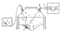
特公昭56−9644号公報の「表面形状検出方法」は、図4に模式的に示すように、光切断用光線としてレーザー光線1を使用し、このレーザー光線を走査用ミラー2で偏向して被測定物体の表面3に投射し、この投射により加熱された表面部分Pから放出される長波長の放射光により被測定物の被加熱部分Pを撮像し、該被加熱部分の軌跡から被測定物体の表面形状を検出するものである。
【0004】
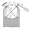
また、特開昭54−65059号公報の「プロファイル測定装置」は、図5に模式的に示すように、繰返し発振するパルスレーザを光源としてレーザビーム5で被測定面3を走査し、被測定面3からの散乱光6を所定の開口径をもつ受光光学系7で集光し、その受光光学系7の焦点面上に描かれる像の軌跡から被測定面3のプロファイルを求めるものである。
【0005】
【発明が解決しようとする課題】
一方、高炉炉頂での原料装入にともなって起こる基本的な物理現象は、▲1▼装入物粒子の集合体としての運動と、▲2▼粒度構成に起因して起こる粒度偏析とからなる。▲1▼の集合体としての運動は、上述した炉頂プロファイルの測定により間接的に把握できるが、▲2▼の粒度偏析は従来測定手段がなく、そのため経験と感に頼って高炉を操業せざるを得ない問題点があった。
【0006】
すなわち、高炉炉頂面のように、高温下で操業されかつ内部に多くの光散乱媒体があり、通常のカメラ等で内部を臨めない場合において、内部に積層する粒子(鉱石やコークス)の粒度(粒径)を計測する適当な手段がなく、かかる手段の開発が従来から強く要望されていた。
【0007】
本発明はかかる要望を満たすために創案されたものである。すなわち、本発明の目的は、高炉炉頂面のように、高温下で操業されかつ内部に多くの光散乱媒体がある環境下で、粒度偏析が測定でき、操業へのフィードバックがかけられる粒度検出装置及び方法を提供することにある。
【0008】
【課題を解決するための手段】
本発明によれば、被測定面にレーザビームを投光するビーム投光装置と、被測定面の投光位置からのレーザビームの散乱光を受光するビーム受光装置と、を備え、前記ビーム投光装置の投光点とビーム受光装置の受光点は、一定の基準長Lを隔てており、更に被測定面演算装置を備え、該被測定面演算装置により、基準長Lに対する投光角αと受光角βとから被測定面の基準長Lからの垂直高さHと投光位置からの水平距離Cとを演算し、更に、投光角αを変化させて被測定面を走査して散乱光の強度が低下する死角ピッチΔαを検出し、該死角ピッチΔαから粒子の粒径Dを演算する、ことを特徴とする粒度検出装置が提供される。本発明の好ましい実施形態によれば、前記被測定面演算装置により、粒径Dを(H2 +C2 )0.5 ×Δαの式で算出する。
【0009】
また、本発明によれば、一定の基準長Lを隔てた投光点と受光点からレーザビームを投光/受光し、基準長Lに対する投光角αと受光角βとから被測定面の基準長Lからの垂直高さHと投光位置からの水平距離Cとを演算し、更に、投光角αを変化させて被測定面を走査して散乱光の強度が低下する死角ピッチΔαを検出し、該死角ピッチΔαから粒子の粒径Dを演算する、ことを特徴とする粒度検出方法が提供される。
【0010】
上述した本発明の装置及び方法によれば、ビーム投光装置、ビーム受光装置、及び被測定面演算装置を備え、一定の基準長Lを隔てた投光点と受光点からレーザビームを投光/受光することにより、三角測量技術(レーザスキャニング等)により基準長Lに対する投光角αと受光角βとから被測定面の基準長Lからの垂直高さHと投光位置からの水平距離Cとを演算することができる。この場合、超高感度光検出技術(ホトン・カウンティング相当)を組み合わせることにより、光散乱媒体が多い場所でも、微弱光信号を正確に検知することができる。
【0011】
更にこの技術を応用し、投光角αを変化させて被測定面を走査する際の散乱光の強度が低下する死角ピッチΔαを検出することにより、この死角ピッチΔαから粒子の粒径Dとその位置(垂直高さHと水平距離C)を演算することができる。
【0012】
【発明の実施の形態】
以下、本発明の好ましい実施形態を図面を参照して説明する。なお、各図において共通する部分には同一の符号を付して使用する。
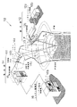
図1は、本発明による粒度検出装置の全体構成図である。この図において、本発明の粒度検出装置10は、被測定面3にレーザビーム5(レーザ光)を投光するビーム投光装置12(投光部)と、被測定面3の投光位置からのレーザビーム5の散乱光6を受光するビーム受光装置14(受光部)と、を備えている。被測定面3は、この図では高炉に装入されたコークスと鉄鉱石の積層面であるが、本発明はこれに限定されず、その他の被測定面にも適用することができる。
【0013】
図1において、ビーム投光装置12(投光部)は、レーザコントローラ12a、レーザ電源12b、レーザ発振器12cおよびミラースキャナ13からなる。ミラースキャナ13は、レーザ発振器から出射されたレーザビームの軸を中心に回転可能な反射ミラーであり、レーザ発振器12cから出射されたレーザビーム5を被測定面3に向けて反射し、かつミラーの揺動により被測定面3を走査するようになっている。
【0014】
ビーム受光装置14(受光部)は、ミラースキャナ14a、レンズ14b、回転式光減衰器14c、フアイバアレイ14dおよび受光制御盤15からなる。ミラースキャナ14aは、反射面に平行な軸を中心に揺動可能な反射ミラーである。ビーム投光装置12で投光される被測定面3の位置に応じてミラーを揺動させ、被測定面3の投光位置からのレーザビーム5の散乱光6を常に安定して受光器アレイ14dに向けて反射させるようになっている。レンズ14bは、ミラースキャナ14aと受光器アレイ14dの中間に位置し、受光器アレイ14dの検出面上に散乱光6を集光する。
【0015】
更に、本発明の粒度検出装置10は、被測定面演算装置16(システム制御部)を備えている。この被測定面演算装置16(システム制御部)は、システム制御盤16aとディスプレイ16bとからなる。
【0016】
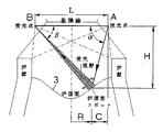
図2は、図1の装置による炉頂プロファイルの測定原理を示す図である。この図に示すように、ビーム投光装置12の投光点Aとビーム受光装置14の受光点Bは、一定の基準長Lを隔てて設置されている。また、上述の被測定面演算装置16により、基準長Lに対する投光角αと受光角βとから被測定面3の基準長Lからの垂直高さHと投光位置Bからの水平距離Cとを演算するようになっている。
【0017】
図3は、図1の装置による粒度検出の測定原理を示す図である。この図に示すように、投光点Aからのレーザビーム5の投光角αを変化(増加又は減少)させて被測定面3を走査すると、投光される被測定面3の位置によっては、受光点Bから被測定面3上の散乱光を観察できない死角が存在する。すなわち、受光点Bからみて粒子の裏側にレーザビーム5が投光される場合には、散乱光はほとんど観察されず、表側を走査する場合のみ散乱光を観察することができる。この散乱光の強度が低下する死角の投光角αに対するピッチ角度Δα(以下、死角ピッチと呼ぶ)は、粒子の直径Dにほぼ比例して増減する。死角ピッチΔαはn番目の死角開始角度αn とn+1番目の死角開始角度αn+1 との差(すなわち、Δα=αn+1 −αn )である。従って、死角ピッチΔαを検出し、被測定面演算装置16により、死角ピッチΔαから粒子の粒径Dとその位置を演算することができる。
【0018】
粒子がほぼ球形であり、死角ピッチΔαがほぼ直径に対応する場合には、幾何学的に、被測定面演算装置16により、粒径Dを(H2 +C2 )0.5 ×Δαの式1で概算値を算出することができる。なお、この式で、Cは投光位置Bからの水平距離であり、L/2−R(Rは半径位置)と置き換えることができる。また、式1におけるHとC(又はR)は、死角ピッチΔαの走査中にも変化するが、概算上はその平均値等を代表値(グローバル値)として用いることができる。更に、実際の鉱石やコークスは、表面が凸凹しており、細いレーザビーム5を用いると死角ピッチΔαが直径に対応しない場合がある。このような場合には、レーザビーム5の投光径を適宜変化させて、粒径Dを代表する死角ピッチΔαが得られるように調節する必要がある。例えば、表面の凹凸が非常に激しい場合には、使用する鉱石又はコークスの既知の直径の半分程度の投光径dを用いることにより、鉱石とコークスの分散状態を把握することができる。
【0019】
上述した装置は、以下のように使用する。
(A)まず、一定の基準長Lを隔てた投光点Aと受光点Bからレーザビーム5を投光/受光し、基準長Lに対する投光角αと受光角βとから被測定面3の基準長Lからの垂直高さHと投光位置Aからの水平距離Cとを演算する。
(B)更に、投光角αを変化させて被測定面3を走査して散乱光の強度が低下する死角ピッチΔαを検出し、この死角ピッチΔαから粒子の粒径Dを演算する。
【0020】
(A)と(B)は、単一の走査により同時に行うことが好ましい。しかし、必要により(A)と(B)を別々のステップとして行うこともできる。
【0021】
なお、本発明は上述した実施形態に限定されず、本発明の要旨を逸脱しない範囲で種々に変更できることは勿論である。
【0022】
【発明の効果】
上述した本発明の装置及び方法によれば、ビーム投光装置、ビーム受光装置、及び被測定面演算装置を備え、一定の基準長Lを隔てた投光点と受光点からレーザビームを投光/受光することにより、三角測量技術により基準長Lに対する投光角αと受光角βとから被測定面の基準長Lからの垂直高さHと投光位置からの水平距離Cとを演算することができる。この場合、超高感度光検出技術(ホトン・カウンティング相当)を組み合わせることにより、光散乱媒体が多い場所でも、微弱光信号を正確に検知することができる。
【0023】
更にこの技術を応用し、投光角αを変化させて被測定面を走査する際の散乱光の強度が低下する死角ピッチΔαを検出することにより、この死角ピッチΔαから粒子の粒径Dとその位置(垂直高さHと水平距離C)を演算することができる。
【0024】
従って、本発明の粒度検出装置は、高炉炉頂面のような、操業中で、かつ内部に多くの光散乱媒体がある環境下で、粒度偏析が測定でき、操業へのフィードバックがかけられる等の優れた効果を有する。
【図面の簡単な説明】
【図1】本発明による粒度検出装置の全体構成図である。
【図2】炉頂プロファイルの測定原理を示す図である。
【図3】粒度検出の測定原理を示す図である。
【図4】炉頂プロファイルを検出する従来例の構成図である。
【図5】炉頂プロファイルを検出する別の従来例の構成図である。
【符号の説明】
1 レーザー光線
2 走査ミラー
3 被測定面
5 レーザビーム
6 散乱光
7 受光光学系
10 粒度検出装置
12 ビーム投光装置(投光部)
13 ミラースキャナ
14 ビーム受光装置(受光部)
14a ミラースキャナ
14b レンズ
14c 回転式光減衰器
14d 受光器アレイ
15 受光制御盤
16 被測定面演算装置(システム制御部)[0001]
BACKGROUND OF THE INVENTION
The present invention relates to a particle size detection apparatus and method for measuring particle size segregation on the top surface of a blast furnace.
[0002]
[Prior art]
In a blast furnace for melting iron ore, coke and iron ore are normally charged alternately from the upper part of the furnace, and thereafter, the profile of the furnace top surface is set to have a V-shaped cross section by a stirrer. The desired V-shape of the furnace top profile has a very important meaning in terms of saving the fuel consumption of the blast furnace, and thus means for accurately measuring the furnace top profile is required.
[0003]
In order to satisfy this requirement, Japanese Patent Publication No. 56-9644, Japanese Patent Laid-Open No. 54-65059, etc. have been proposed and applied.
The “surface shape detection method” disclosed in Japanese Examined Patent Publication No. 56-9644 uses a
[0004]
Further, as schematically shown in FIG. 5, the “profile measuring device” disclosed in Japanese Patent Application Laid-Open No. 54-65059 scans the surface to be measured 3 with a
[0005]
[Problems to be solved by the invention]
On the other hand, the basic physical phenomenon that occurs with the raw material charging at the top of the blast furnace is as follows: (1) Movement as an aggregate of charged particles and (2) Particle size segregation caused by particle size composition. Become. The movement of (1) as an assembly can be grasped indirectly by measuring the furnace top profile as described above, but the particle size segregation of (2) has no conventional measuring means, so the blast furnace is operated by relying on experience and feeling. There was an inevitable problem.
[0006]
In other words, the particle size of the particles (ore and coke) stacked inside when operating at high temperatures and there are many light scattering media inside, such as the top surface of a blast furnace, where the inside cannot be viewed with a normal camera, etc. There is no appropriate means for measuring (particle size), and there has been a strong demand for the development of such means.
[0007]
The present invention has been developed to meet such a demand. That is, the object of the present invention is to detect particle size segregation in an environment where there is a large number of light scattering media inside and operated at a high temperature, such as the top surface of a blast furnace, and particle size detection that can be fed back to the operation. It is to provide an apparatus and method.
[0008]
[Means for Solving the Problems]
According to the present invention, there is provided a beam projecting device that projects a laser beam onto a surface to be measured, and a beam receiving device that receives scattered light of the laser beam from a projecting position on the surface to be measured. The light projecting point of the optical device and the light receiving point of the beam receiving device are separated from each other by a certain reference length L, and further includes a measured surface arithmetic device, and the projected surface angle α with respect to the reference length L is measured by the measured surface arithmetic device. And the light receiving angle β, the vertical height H from the reference length L of the surface to be measured and the horizontal distance C from the light projection position are calculated, and the surface to be measured is scanned by changing the light projection angle α. There is provided a particle size detection apparatus characterized by detecting a blind spot pitch Δα at which the intensity of scattered light decreases and calculating a particle diameter D of the particle from the blind spot pitch Δα. According to a preferred embodiment of the present invention, the particle size D is calculated by the equation (H 2 + C 2 ) 0.5 × Δα by the measured surface arithmetic device.
[0009]
Further, according to the present invention, the laser beam is projected / received from the light projecting point and the light receiving point separated by a certain reference length L, and the surface to be measured is determined from the light projecting angle α and the light receiving angle β with respect to the reference length L. The vertical height H from the reference length L and the horizontal distance C from the light projection position are calculated, and the blind angle Δα at which the surface to be measured is scanned by changing the light projection angle α to reduce the intensity of the scattered light. Is detected, and the particle size D of the particle is calculated from the blind spot pitch Δα.
[0010]
According to the apparatus and method of the present invention described above, a beam projecting device, a beam receiving device, and a measured surface computing device are provided, and a laser beam is projected from the projecting point and the receiving point separated by a certain reference length L. / By receiving light, the vertical height H from the reference length L of the surface to be measured and the horizontal distance from the light projection position from the projection angle α and the light reception angle β with respect to the reference length L by triangulation technology (laser scanning etc.) C can be calculated. In this case, by combining ultra-high sensitivity light detection technology (equivalent to photon counting), it is possible to accurately detect a weak light signal even in a place where there are many light scattering media.
[0011]
Further, this technique is applied to detect a blind spot pitch Δα at which the intensity of scattered light decreases when scanning the surface to be measured by changing the projection angle α, and from this blind spot pitch Δα, the particle diameter D of the particle is obtained. The position (vertical height H and horizontal distance C) can be calculated.
[0012]
DETAILED DESCRIPTION OF THE INVENTION
Hereinafter, preferred embodiments of the present invention will be described with reference to the drawings. In addition, the same code | symbol is attached | subjected and used for the common part in each figure.
FIG. 1 is an overall configuration diagram of a particle size detection apparatus according to the present invention. In this figure, a particle
[0013]
In FIG. 1, a beam projector 12 (projector) includes a
[0014]
The beam receiving device 14 (light receiving unit) includes a
[0015]
Furthermore, the particle
[0016]
FIG. 2 is a diagram showing the measurement principle of the furnace top profile by the apparatus of FIG. As shown in this figure, the light projecting point A of the beam projecting device 12 and the light receiving point B of the
[0017]
FIG. 3 is a diagram showing the measurement principle of particle size detection by the apparatus of FIG. As shown in this figure, when the
[0018]
When the particles are substantially spherical and the blind spot pitch Δα substantially corresponds to the diameter, geometrically, the particle size D is expressed by
[0019]
The apparatus described above is used as follows.
(A) First, the
(B) Further, by changing the projection angle α, the surface to be measured 3 is scanned to detect the dead angle pitch Δα at which the intensity of the scattered light decreases, and the particle diameter D of the particle is calculated from the dead angle pitch Δα.
[0020]
(A) and (B) are preferably performed simultaneously by a single scan. However, if necessary, (A) and (B) can be performed as separate steps.
[0021]
In addition, this invention is not limited to embodiment mentioned above, Of course, it can change variously in the range which does not deviate from the summary of this invention.
[0022]
【The invention's effect】
According to the apparatus and method of the present invention described above, a beam projecting device, a beam receiving device, and a measured surface computing device are provided, and a laser beam is projected from the projecting point and the receiving point separated by a certain reference length L. / By receiving light, the vertical height H from the reference length L of the surface to be measured and the horizontal distance C from the light projection position are calculated from the projection angle α and the reception angle β with respect to the reference length L by the triangulation technique. be able to. In this case, by combining ultra-high sensitivity light detection technology (equivalent to photon counting), it is possible to accurately detect a weak light signal even in a place where there are many light scattering media.
[0023]
Further, this technique is applied to detect a blind spot pitch Δα at which the intensity of scattered light decreases when scanning the surface to be measured by changing the projection angle α, and from this blind spot pitch Δα, the particle diameter D of the particle is obtained. The position (vertical height H and horizontal distance C) can be calculated.
[0024]
Therefore, the particle size detection apparatus of the present invention can measure particle size segregation in an environment where there are many light scattering media inside such as the top surface of a blast furnace, and feedback to the operation is applied. It has an excellent effect.
[Brief description of the drawings]
FIG. 1 is an overall configuration diagram of a particle size detection apparatus according to the present invention.
FIG. 2 is a diagram showing a measurement principle of a furnace top profile.
FIG. 3 is a diagram illustrating a measurement principle of particle size detection.
FIG. 4 is a configuration diagram of a conventional example for detecting a furnace top profile.
FIG. 5 is a configuration diagram of another conventional example for detecting a furnace top profile.
[Explanation of symbols]
DESCRIPTION OF
13
Claims (3)
更に被測定面演算装置を備え、該被測定面演算装置により、基準長Lに対する投光角αと受光角βとから被測定面の基準長Lからの垂直高さHと投光位置からの水平距離Cとを演算し、更に、投光角αを変化させて被測定面を走査して散乱光の強度が低下する死角ピッチΔαを検出し、該死角ピッチΔαから粒子の粒径Dを演算する、ことを特徴とする粒度検出装置。A beam projecting device for projecting a laser beam on the surface to be measured; and a beam receiving device for receiving the scattered light of the laser beam from the projecting position on the surface to be measured, the projecting point of the beam projecting device And the light receiving point of the beam receiving device are separated by a certain reference length L,
Further, a measurement surface calculation device is provided, and from the projection angle α and the light reception angle β with respect to the reference length L, the measurement surface calculation device calculates the vertical height H from the reference length L of the measurement surface and the projection position. The horizontal distance C is calculated, and further, the projection angle α is changed to scan the surface to be measured to detect the dead angle pitch Δα at which the scattered light intensity decreases, and the particle diameter D of the particle is determined from the dead angle pitch Δα. A particle size detection apparatus characterized by calculating.
Priority Applications (1)
| Application Number | Priority Date | Filing Date | Title |
|---|---|---|---|
| JP33655396A JP3661900B2 (en) | 1996-12-17 | 1996-12-17 | Particle size detection apparatus and method |
Applications Claiming Priority (1)
| Application Number | Priority Date | Filing Date | Title |
|---|---|---|---|
| JP33655396A JP3661900B2 (en) | 1996-12-17 | 1996-12-17 | Particle size detection apparatus and method |
Publications (2)
| Publication Number | Publication Date |
|---|---|
| JPH10176908A JPH10176908A (en) | 1998-06-30 |
| JP3661900B2 true JP3661900B2 (en) | 2005-06-22 |
Family
ID=18300336
Family Applications (1)
| Application Number | Title | Priority Date | Filing Date |
|---|---|---|---|
| JP33655396A Expired - Fee Related JP3661900B2 (en) | 1996-12-17 | 1996-12-17 | Particle size detection apparatus and method |
Country Status (1)
| Country | Link |
|---|---|
| JP (1) | JP3661900B2 (en) |
Families Citing this family (2)
| Publication number | Priority date | Publication date | Assignee | Title |
|---|---|---|---|---|
| US7355694B2 (en) | 2002-09-10 | 2008-04-08 | Sapporo Breweries Limited | Method and apparatus for measuring a particle diameter of foam on a malt alcoholic drink |
| JP5053193B2 (en) * | 2008-07-17 | 2012-10-17 | 新日本製鐵株式会社 | Particle size measuring apparatus and particle size measuring method |
-
1996
- 1996-12-17 JP JP33655396A patent/JP3661900B2/en not_active Expired - Fee Related
Also Published As
| Publication number | Publication date |
|---|---|
| JPH10176908A (en) | 1998-06-30 |
Similar Documents
| Publication | Publication Date | Title |
|---|---|---|
| US5442573A (en) | Laser thickness gauge | |
| AU663397B2 (en) | Measurement of transparent container wall thickness | |
| US8503046B2 (en) | Rotating prism scanning device and method for scanning | |
| US5309222A (en) | Surface undulation inspection apparatus | |
| US3858983A (en) | Shaped product measurement | |
| JPH01253607A (en) | Optical detection method and apparatus for surface roughness of material surface | |
| US5153445A (en) | Method and apparatus for measuring orange peel and texture in painted surfaces | |
| US5880843A (en) | Apparatus and method for determining the optical distortion of a transparent substrate | |
| US4296333A (en) | Method and apparatus for detecting surface defects in a workpiece | |
| JPS5818103A (en) | Shape measuring method for plane to be measured under environment with scattered substance | |
| JPH10176908A (en) | Particle size detection apparatus and method | |
| JPH10221163A (en) | Fire detector | |
| JPH10122842A (en) | Steel plate flatness measurement method | |
| JP3848310B2 (en) | Glass bottle inspection equipment | |
| JPH0318882Y2 (en) | ||
| JPH08193810A (en) | Device for measuring displacement | |
| JPH09505883A (en) | Equipment for measuring the dimensions of large objects | |
| JP3444575B2 (en) | Rangefinder | |
| JP2663525B2 (en) | Strain inspection device | |
| JPH076776B2 (en) | Hot coil winding shape detector | |
| JPS62115315A (en) | Laser displacement gauge | |
| JPH0344504A (en) | Method and apparatus for measuring three-dimensional shape of surface | |
| JP2815808B2 (en) | Radiation thermometer | |
| JPH0650715A (en) | Optical displacement cage | |
| JP4300496B2 (en) | Optical profile measuring method and apparatus |
Legal Events
| Date | Code | Title | Description |
|---|---|---|---|
| A977 | Report on retrieval |
Free format text: JAPANESE INTERMEDIATE CODE: A971007 Effective date: 20050228 |
|
| TRDD | Decision of grant or rejection written | ||
| A01 | Written decision to grant a patent or to grant a registration (utility model) |
Free format text: JAPANESE INTERMEDIATE CODE: A01 Effective date: 20050304 |
|
| A61 | First payment of annual fees (during grant procedure) |
Free format text: JAPANESE INTERMEDIATE CODE: A61 Effective date: 20050317 |
|
| FPAY | Renewal fee payment (event date is renewal date of database) |
Free format text: PAYMENT UNTIL: 20080401 Year of fee payment: 3 |
|
| S531 | Written request for registration of change of domicile |
Free format text: JAPANESE INTERMEDIATE CODE: R313531 |
|
| S533 | Written request for registration of change of name |
Free format text: JAPANESE INTERMEDIATE CODE: R313533 |
|
| FPAY | Renewal fee payment (event date is renewal date of database) |
Free format text: PAYMENT UNTIL: 20080401 Year of fee payment: 3 |
|
| R350 | Written notification of registration of transfer |
Free format text: JAPANESE INTERMEDIATE CODE: R350 |
|
| FPAY | Renewal fee payment (event date is renewal date of database) |
Free format text: PAYMENT UNTIL: 20080401 Year of fee payment: 3 |
|
| FPAY | Renewal fee payment (event date is renewal date of database) |
Free format text: PAYMENT UNTIL: 20090401 Year of fee payment: 4 |
|
| FPAY | Renewal fee payment (event date is renewal date of database) |
Free format text: PAYMENT UNTIL: 20090401 Year of fee payment: 4 |
|
| FPAY | Renewal fee payment (event date is renewal date of database) |
Free format text: PAYMENT UNTIL: 20100401 Year of fee payment: 5 |
|
| FPAY | Renewal fee payment (event date is renewal date of database) |
Free format text: PAYMENT UNTIL: 20100401 Year of fee payment: 5 |
|
| FPAY | Renewal fee payment (event date is renewal date of database) |
Free format text: PAYMENT UNTIL: 20110401 Year of fee payment: 6 |
|
| FPAY | Renewal fee payment (event date is renewal date of database) |
Free format text: PAYMENT UNTIL: 20120401 Year of fee payment: 7 |
|
| FPAY | Renewal fee payment (event date is renewal date of database) |
Free format text: PAYMENT UNTIL: 20120401 Year of fee payment: 7 |
|
| FPAY | Renewal fee payment (event date is renewal date of database) |
Free format text: PAYMENT UNTIL: 20130401 Year of fee payment: 8 |
|
| FPAY | Renewal fee payment (event date is renewal date of database) |
Free format text: PAYMENT UNTIL: 20140401 Year of fee payment: 9 |
|
| LAPS | Cancellation because of no payment of annual fees |